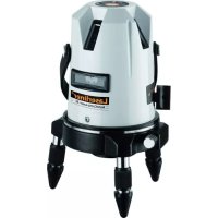
AutoCrossLaser 3C Plus - Hand tool Laserliner - Free user manual and instructions
Find the device manual for free AutoCrossLaser 3C Plus Laserliner in PDF.

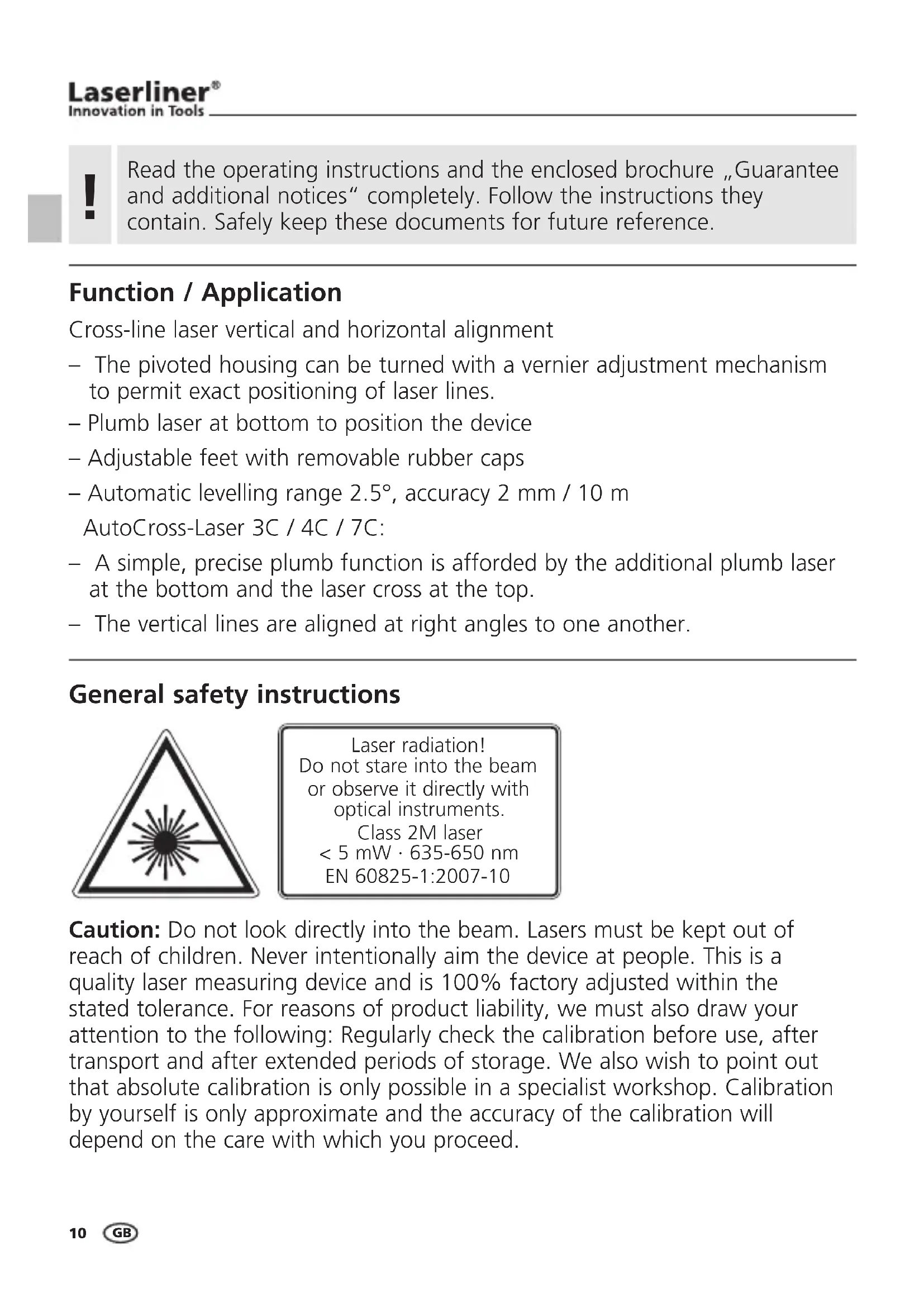


| Product Type | Cross-line laser level (hand tool) |
| Model | AutoCrossLaser 3C Plus |
| Brand | Laserliner |
| Lasers | 1 horizontal, 2 vertical, 1 plumb (downpoint) |
| Laser Wavelength | 635 nm (line laser) / 650 nm (plumb laser) |
| Laser Class | 2M (line) / 2 (plumb) |
| Output Power | < 5 mW (line) / < 1 mW (plumb) |
| Self-levelling Range | ± 2.5° |
| Precision | ± 2 mm / 10 m |
| Power Supply | 3 x 1.5V AA batteries |
| Operating Time | Approx. 16 hours |
| Operating Temperature | 0°C to +50°C |
| Storage Temperature | -10°C to +70°C |
| Weight (incl. batteries) | 1.4 kg |
| Dimensions (W x H x D) | 120 x 190 x 120 mm |
| Mounting Thread | 5/8" (bottom) |
| Special Features | PowerBright technology, RX-READY, vernier adjustment, adjustable feet, pendulum lock, tripod adapter |
| Battery Indicator | Low battery warning via flashing bubble level |
| Calibration Check | User-performed with 2-wall method |
| Safety | Class 2M laser, do not stare into beam, keep away from children |
| Maintenance | Check calibration regularly, clean with soft cloth, store in dry place |
| Compliance | CE, WEEE directive |
Frequently Asked Questions - AutoCrossLaser 3C Plus Laserliner
User questions about AutoCrossLaser 3C Plus Laserliner
0 question about this device. Answer the ones you know or ask your own.
Ask a new question about this device
Download the instructions for your Hand tool in PDF format for free! Find your manual AutoCrossLaser 3C Plus - Laserliner and take your electronic device back in hand. On this page are published all the documents necessary for the use of your device. AutoCrossLaser 3C Plus by Laserliner.
USER MANUAL AutoCrossLaser 3C Plus Laserliner
natural_image
Exterior view of a Laserliner (AutoCross-Laser X) measurement device with four tripod legs and control knobs (no visible text or symbols on the device itself)
natural_image
White industrial vacuum cleaner with four wheels and control panel (no visible text or symbols)
natural_image
Exterior view of a white industrial vacuum cleaner with four wheels and control panel (no visible text or symbols)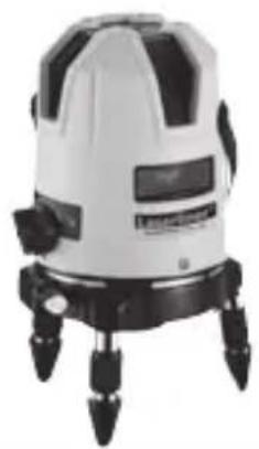
natural_image
White and black industrial water purifier with four wheels (no visible text or symbols)AUTOMATIC
LEVEL



Laser
635-650 nm

PowerBright
LASER
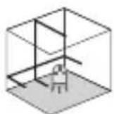
AutoCross-Laser 2C
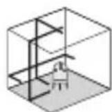
AutoCross-Laser 3C
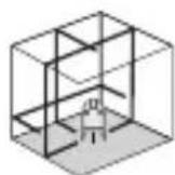
AutoCross-Laser 4C
AutoCross-Laser 7C
Laserliner®
Innovation in Tools
DE 02
GB 10
NL 18
DK 26
FR 34
ES 42
IT 50
PL 58
FI 66
PT 74
SE 82
NO
TR
RU
UA
CZ
EE
LV
LT
RO
BG
GR
!
natural_image
Pure electrical circuit lines without any symbolsAutoCross-Laser
7C
natural_image
Pure electrical circuit lines without any symbolsAutoCross-Laser 2C AutoCross-Laser 3C

Read the operating instructions and the enclosed brochure „Guarantee and additional notices“ completely. Follow the instructions they contain. Safely keep these documents for future reference.
Function / Application
Cross-line laser vertical and horizontal alignment
- The pivoted housing can be turned with a vernier adjustment mechanism to permit exact positioning of laser lines.
- Plumb laser at bottom to position the device
- Adjustable feet with removable rubber caps
– Automatic levelling range 2.5°, accuracy 2 mm / 10 m
AutoCross-Laser 3C / 4C / 7C:
- A simple, precise plumb function is afforded by the additional plumb laser at the bottom and the laser cross at the top.
- The vertical lines are aligned at right angles to one another.
General safety instructions

Laser radiation! Do not stare into the beam or observe it directly with optical instruments.
Class 2M laser < 5 mW · 635-650 nm EN 60825-1:2007-10
Caution: Do not look directly into the beam. Lasers must be kept out of reach of children. Never intentionally aim the device at people. This is a quality laser measuring device and is 100% factory adjusted within the stated tolerance. For reasons of product liability, we must also draw your attention to the following: Regularly check the calibration before use, after transport and after extended periods of storage. We also wish to point out that absolute calibration is only possible in a specialist workshop. Calibration by yourself is only approximate and the accuracy of the calibration will depend on the care with which you proceed.
Special product features

LEVEL Automatic alignment of the device with a magnetically dampened pendulum system. The device is brought into initial position and aligns itself autonomously.

Transport LOCK: The device is protected with a pendelum lock during transport.

PowerBright LASER Devices with PowerBright technology have special high- performance diodes to produce super bright laser lines These remain visible over longer distances, in bright ambient light and on dark surfaces.

RX-READY technology enables line lasers to be used even in unfavourable light conditions. The laser lines pulsate at a high frequency and this can be picked up by special laser receivers over long distances.
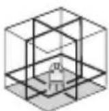
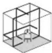
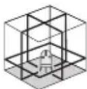
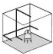
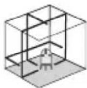
Number and direction of the lasers
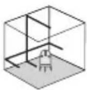
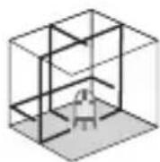
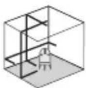
H = horizontal laser / V = vertical laser / D = downpoint
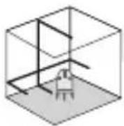
AutoCross-Laser 2C
1H 1V 1D
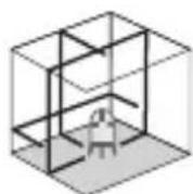
AutoCross-Laser 4C
1H 3V 1D
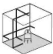
AutoCross-Laser 3C
1H 2V 1D
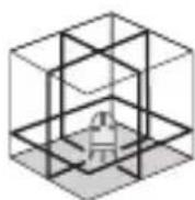
AutoCross-Laser 7C
3H 4V 1D
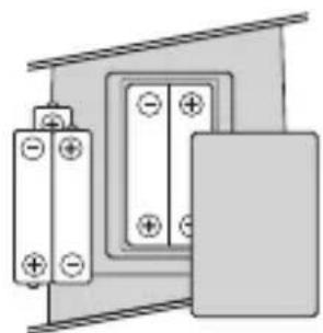
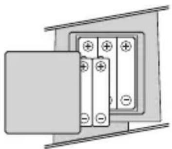
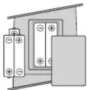
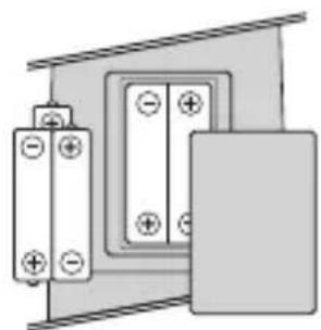
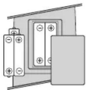
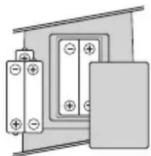
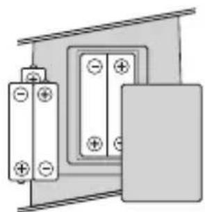
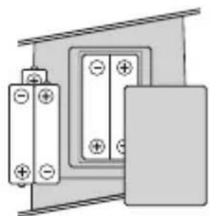
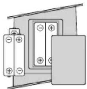
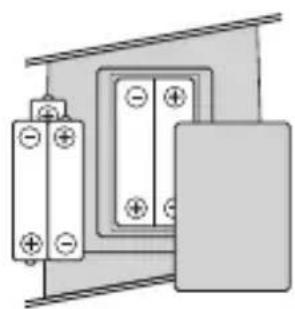
1Inserting the batteries
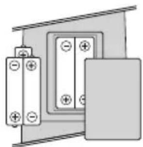
Open the battery compartment (9) and insert the batteries in accordance with the installation symbols, ensuring the correct polarity.
AutoCross-Laser
2C / 3C / 4C
natural_image
Pure electrical circuit lines without any symbolsAutoCross-Laser
7C
natural_image
Pure electrical circuit lines without any symbolsAutoCross-Laser 2C AutoCross-Laser 3C
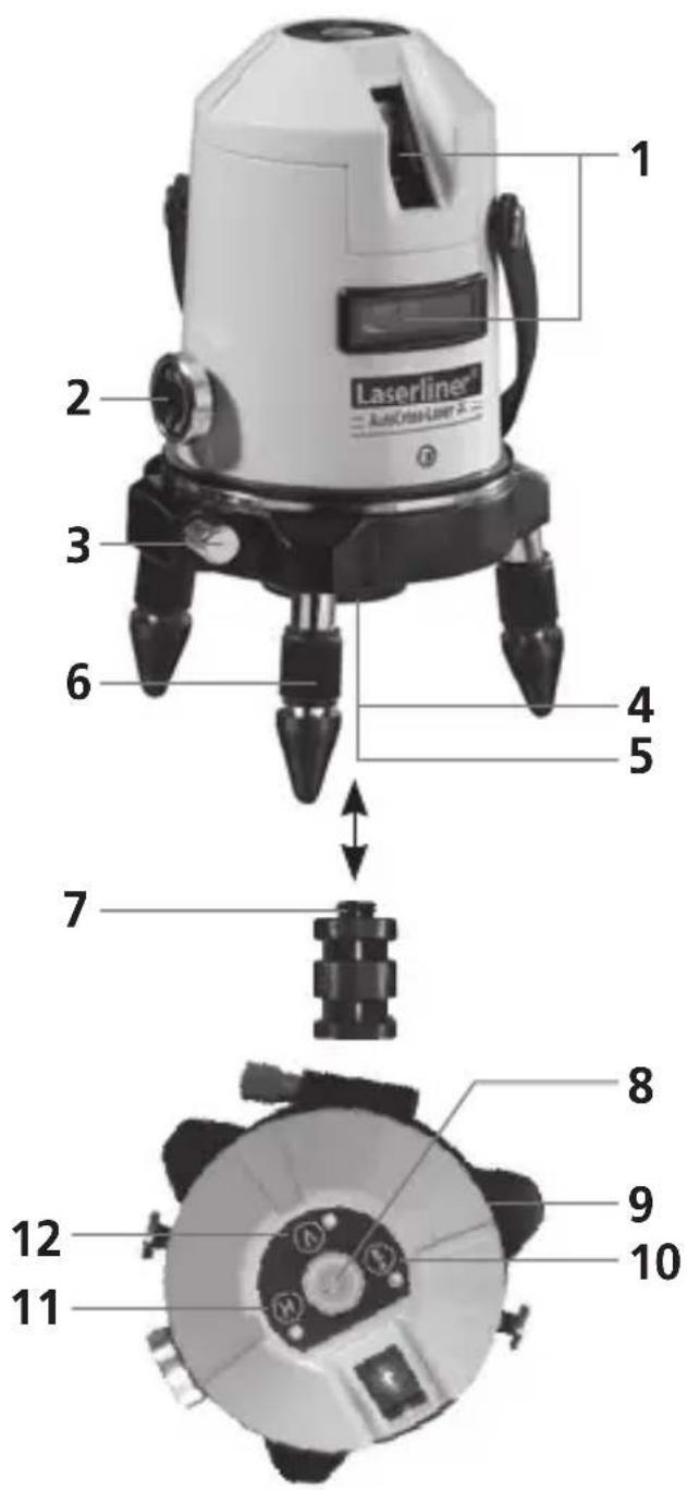
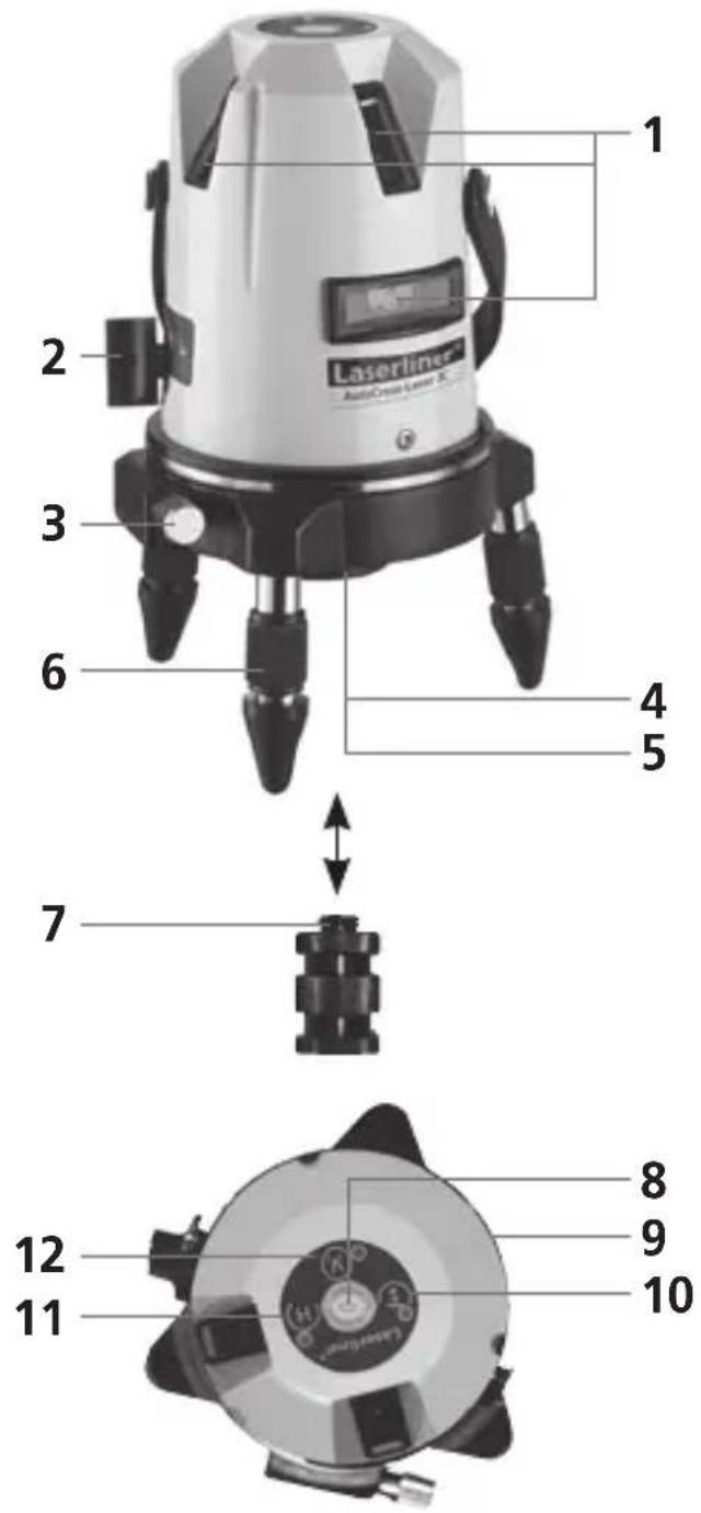
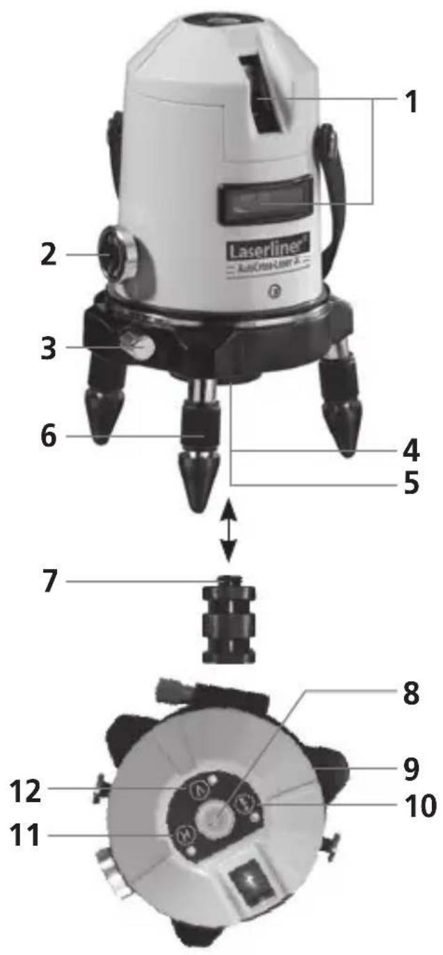
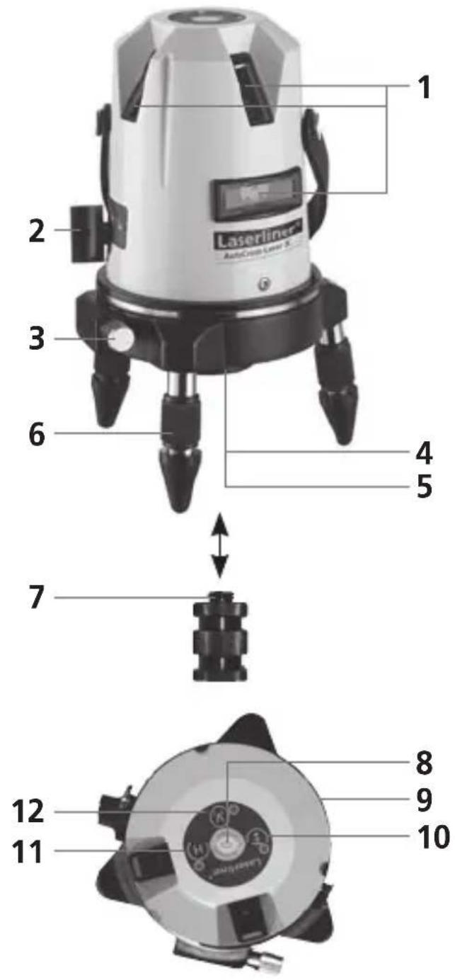
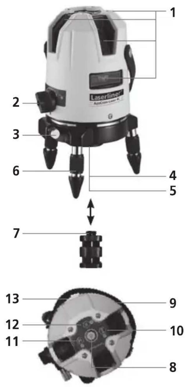
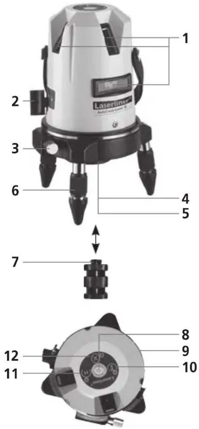
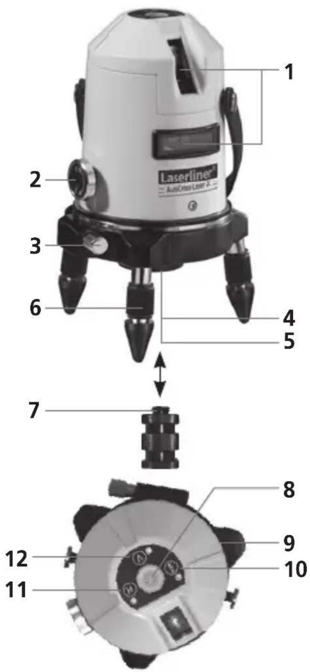
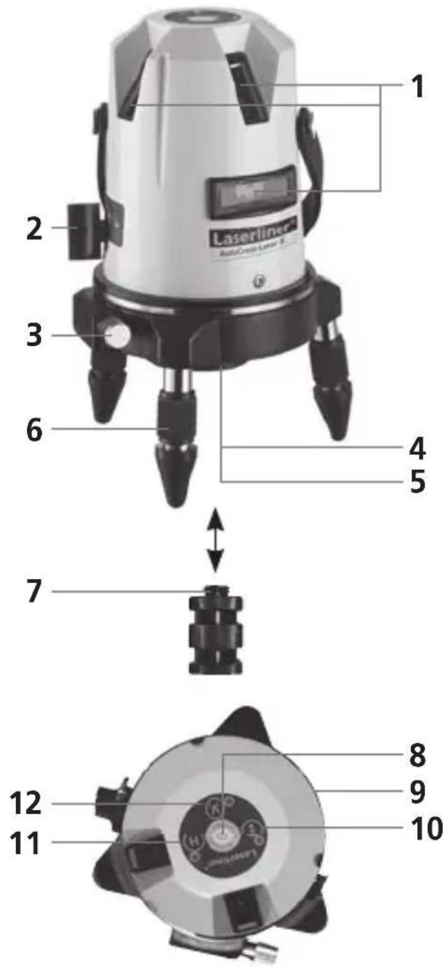
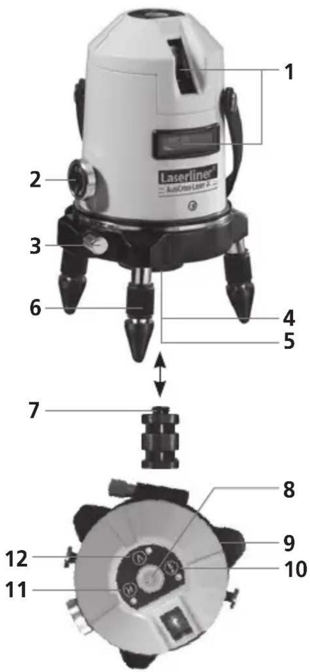
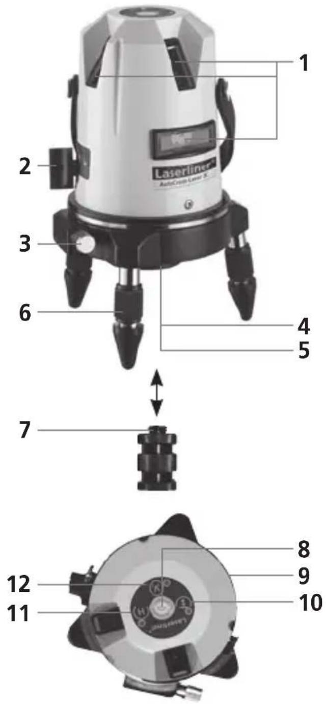
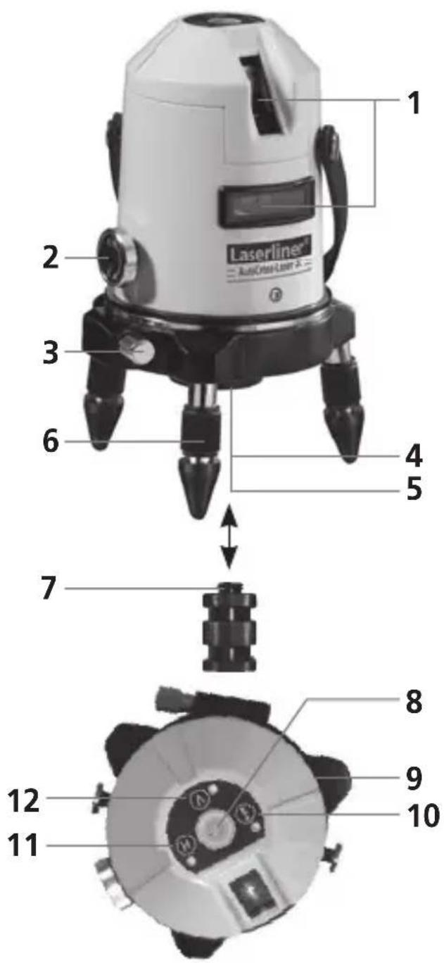
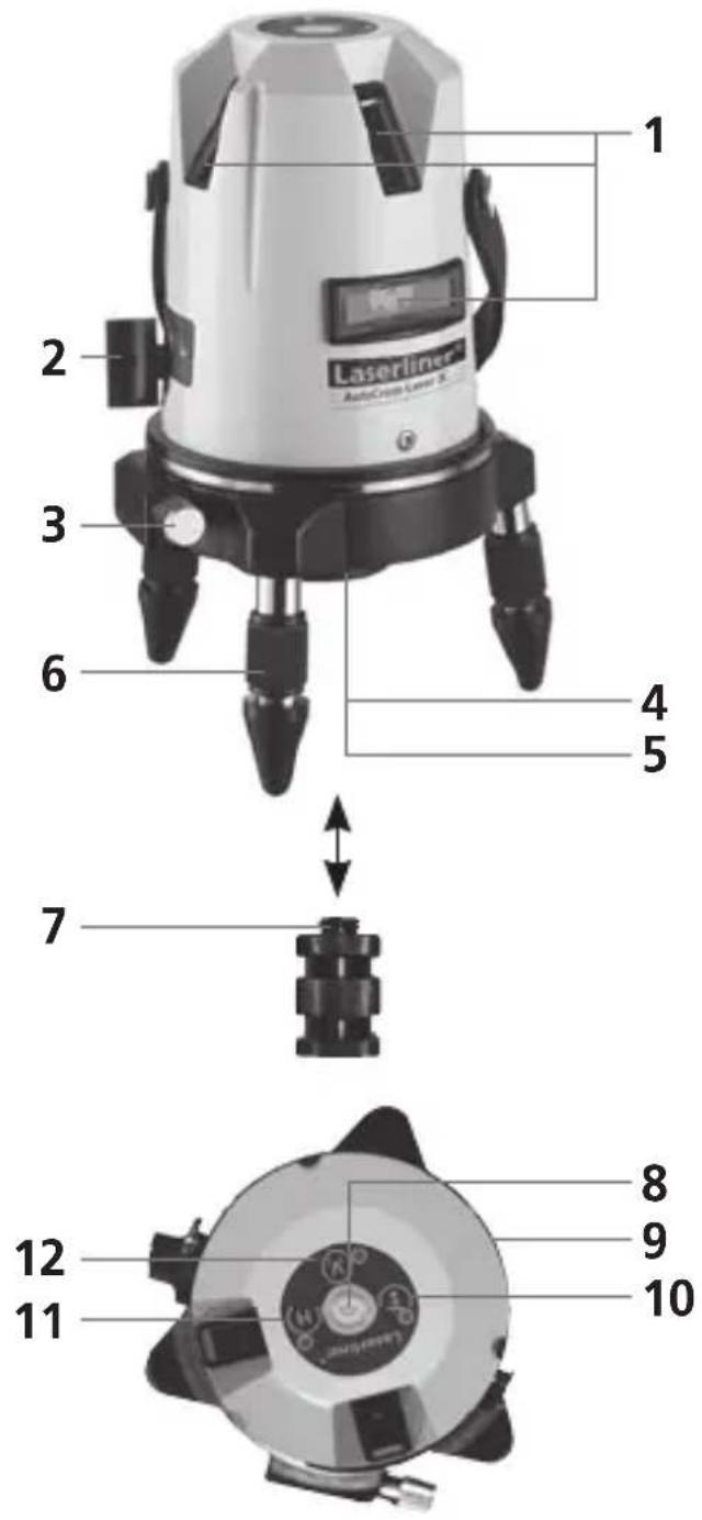
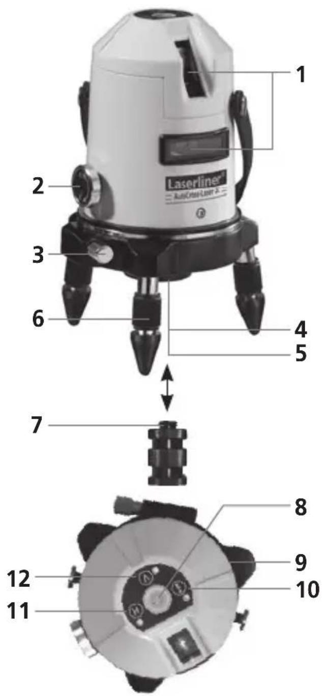
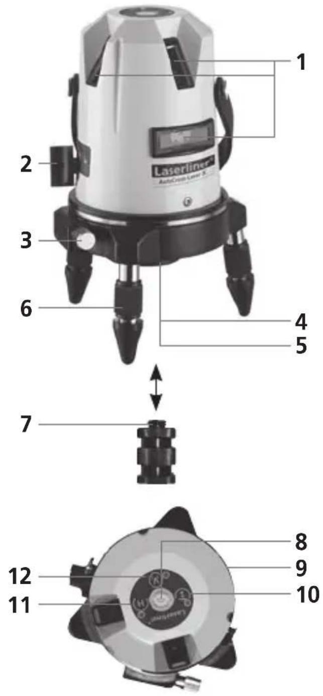
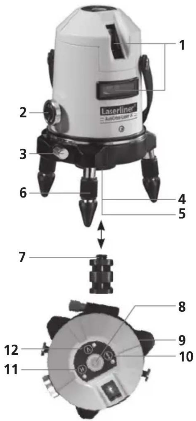
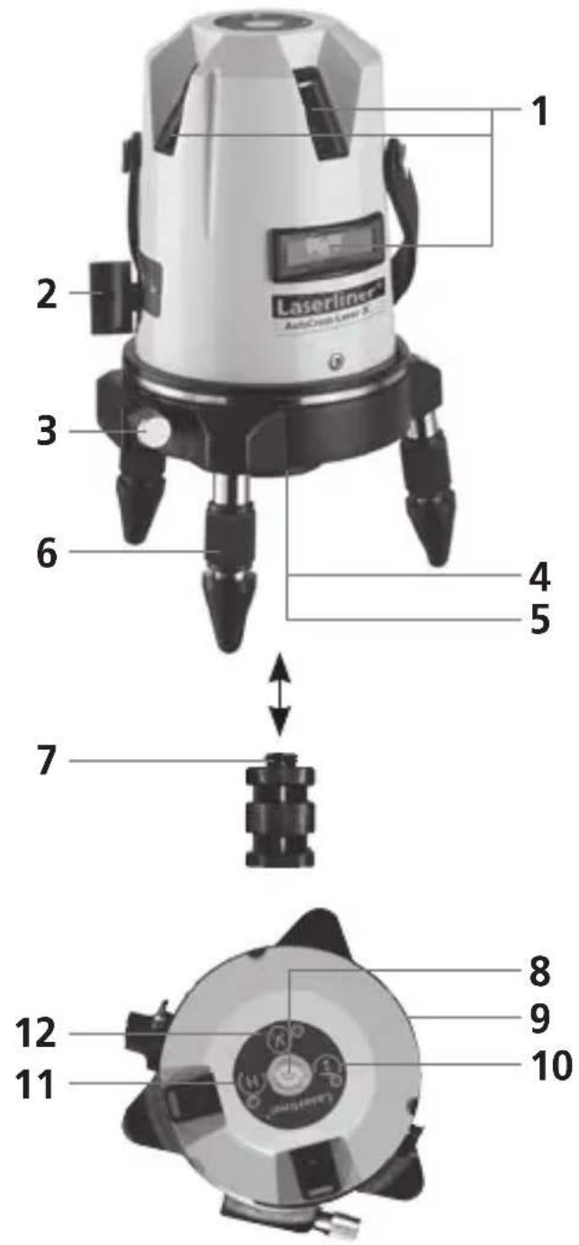
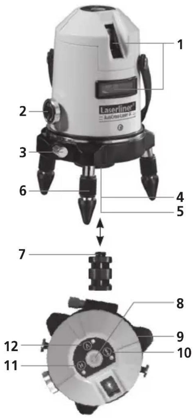
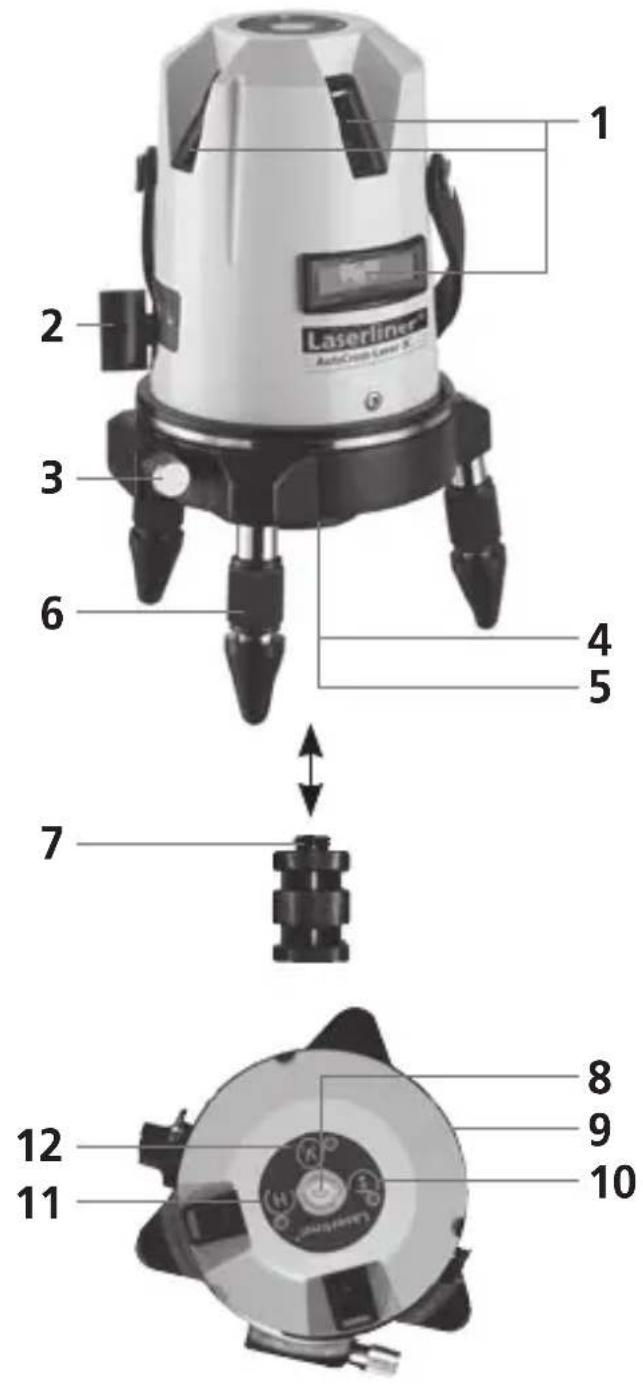
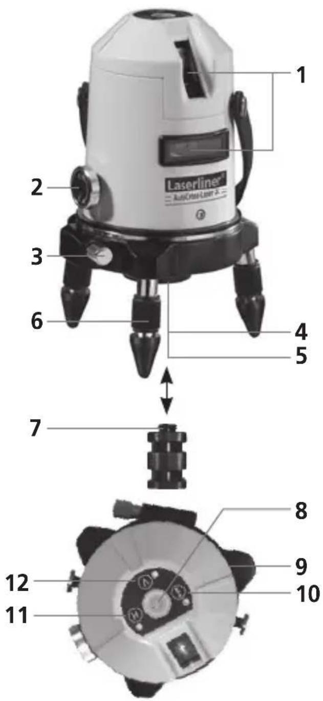
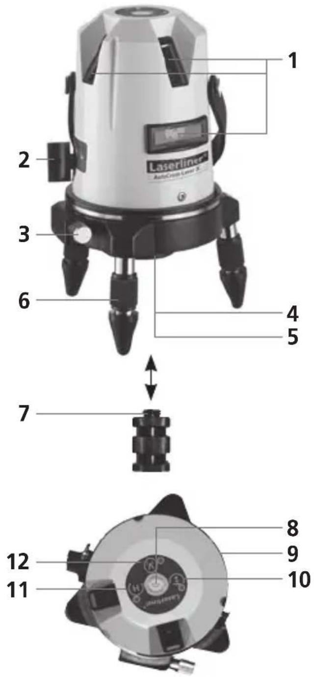
1 Laser emitting window
2 ON / OFF switch; Transport fastener
3 Vernier adjustment
4 5/8" thread (bottom)
5 Window for plumb laser (underside)
6 Adjustable feet with removable rubber caps
7 Tripod adapter
8 Vial for approximate alignment / Low bat. display: Low battery charge when bubble level flashes
9 Battery compartment
AutoCross-Laser 4C AutoCross-Laser 7C
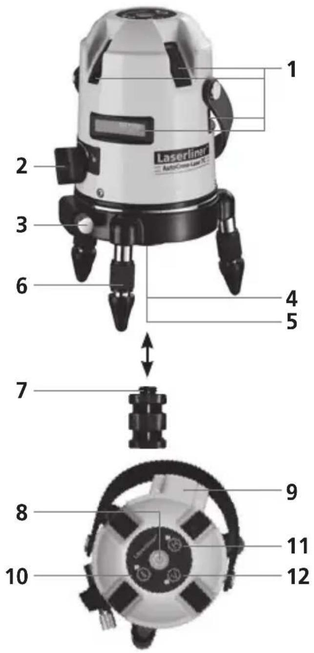
10 Hand receiver mode
11 Horizontal laser lines
12 Vertical laser line
13 Connecting socket for mains adapter (6 V/1000 mA, no charging function)
!
For transport, the device must always be switched off with the transport securing device (2) so as to protect device from damage.
2Horizontal and vertical levelling
Turn the transport fastener (2) clockwise and release the pendulum lock. The lasers are now automatically aligned by the pendulum system and the horizontal laser lights constantly. The lasers can be switched on and off individually with the H and V buttons. It is now ready for levelling in the horizontal or vertical plane.
!
If the device is too far off the horizontal (more than 2.5°), the lasers will blink. Align the device using the adjustable feet (6) or place on a more level surface. The round vial (8) is provided as an aid to alignment.
B Positioning laser lines
The top section of the laser unit can be turned on the plinth to align the lasers approximately. Precise positioning can then be done with the Vernier adjustment (3). The adjustable feet (6) allow the device to be positioned on sloping surfaces.
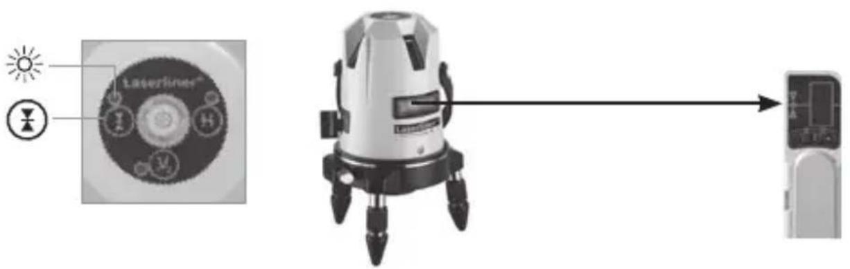
4 Hand receiver mode
Optional: Working with the laser receiver RX
Use an RX laser receiver (optional) to carry out levelling at great distances or when the laser lines are no longer visible.
To work with a laser receiver, switch the line laser into hand receiver mode with the Hand receiver mode button (10). The laser lines will now pulsate with high frequency, making the laser lines darker. The laser receiver RX can detect these pulsating laser lines.
!
Follow the operating instructions of the corresponding laser receiver.
Preparing the calibration check:
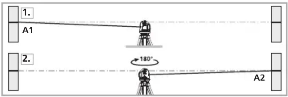
It is possible for you to check the calibration of the laser. To do this, position the device midway between 2 walls, which must be at least 5 metres apart. Do this by turning the unit on, thus releasing the transport restraint (cross laser on). Please use a tripod.
- Mark point A1 on the wall.
- Turn the device through 180^ and mark point A2. You now have a horizontal reference between points A1 and A2.
Performing the calibration check:
- Position the device as near as possible to the wall at the height of point A1.
- Turn the device through 180^ and mark point A3. The difference between points A2 and A3 is the tolerance.
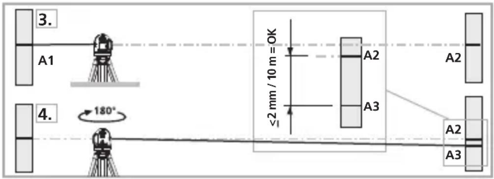

When A2 and A3 are more than 2 mm / 10 m apart, an adjustment is necessary. Contact your authorised dealer or else the UMAREX-LASERLINER Service Department.
Checking the vertical line:
Position the device about 5 m from a wall. Fix a plumb bob with a line of 2.5 m length on the wall, making sure that the bob can swing freely. Switch on the device and align the vertical laser to the plumb line. The precision is within the specified tolerance if the deviation between the laser line and the plumb line is not greater than ± 1.5 mm.
Checking the horizontal line:
Position the device about 5 m from a wall and switch on the cross laser. Mark point B on the wall. Turn the laser cross approx. 2.5 m to the right and mark point C. Check whether the horizontal line from point C is level with point B to within ± 2 mm. Repeat the process by turning the laser to the left.
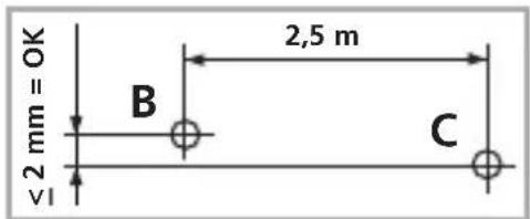

Regularly check the adjustment before use, after transport and after extended periods of storage.
EU directives and disposal
This device complies with all necessary standards for the free movement of goods within the EU.
This product is an electric device and must be collected separately for disposal according to the European Directive on waste electrical and electronic equipment.
Further safety and supplementary notices at:
www.laserliner.com/info
| Technical data (Subject to technical alterations) | |
| Self-levelling range ± 2.5° | |
| Precision ± 2 mm / 10 m | |
| Laser wavelength linelaser / plumb laser | 635 nm / 650 nm |
| Laser class / line laser output power | 2M / < 5 mW(EN 60825-1:2007-10) |
| Laser class / plumb laser output power | 2 / < 1 mW(EN 60825-1:2007-10) |
| Power supply | 3 x 1.5V AA |
| Operating time ACL 2C / ACL 3C approx. 16 h | |
| Operating time ACL 4C approx. 12 h | |
| Operating time ACL 7C approx. 9 h | |
| Operating temperature 0°C ... + 50°C | |
| Storage temperature -10°C ... + 70°C | |
| Weight ACL 2C (incl. battery) 1.2 kg | |
| Weight ACL 3C / ACL 7C (incl. battery) 1.4 kg | |
| Weight ACL 4C (incl. battery) 1.6 kg | |
| Dimensions ACL 2C (W x H x D) 110 x 185 x 115 mm | |
| Dimensions ACL 3C (W x H x D) 120 x 190 x 120 mm | |
| Dimensions ACL 4C / 7C (W x H x D) 120 x 195 x | 130 mm |
!
H = horizontale laser / V = verticale laser / D = loodlaser (downpoint)
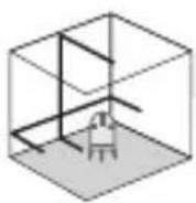
AutoCross-Laser 2C 1H 1V 1D
AutoCross-Laser 4C 1H 3V 1D
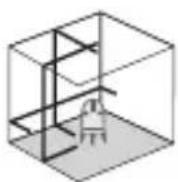
AutoCross-Laser 3C 1H 2V 1D
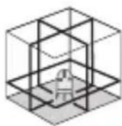
AutoCross-Laser 7C 3H 4V 1D
natural_image
Pure electrical circuit lines without any symbolsAutoCross-Laser
7C
natural_image
Pure electrical circuit lines without any symbolsAutoCross-Laser 2C AutoCross-Laser 3C


H = horizontal laser / V = vertical laser / D = lodlaser (downpoint)
AutoCross-Laser 2C
1H 1V 1D
AutoCross-Laser 4C
1H 3V 1D
AutoCross-Laser 3C
1H 2V 1D
AutoCross-Laser 7C
3H 4V 1D
natural_image
Pure electrical circuit lines without any symbolsAutoCross-Laser
7C
natural_image
Pure electrical circuit lines without any symbolsAutoCross-Laser 2C AutoCross-Laser 3C
1 Laserudgangsvindue
2 Tænd-/sluk kontakt; Transportsikring
3 Justerskrue til finindstilling
4 5/8" gevindbøsning (underside)
5 Åbning for lodlaser (underside)

natural_image
Pure electrical circuit lines without any symbolsAutoCross-Laser
7C
natural_image
Pure electrical circuit lines without any symbolsAutoCross-Laser 2C AutoCross-Laser 3C

natural_image
Pure electrical circuit lines without any symbolsAutoCross-Laser
7C
natural_image
Pure electrical circuit lines without any symbolsAutoCross-Laser 2C AutoCross-Laser 3C

natural_image
Pure electrical circuit lines without any symbolsAutoCross-Laser
7C

natural_image
Pure electrical circuit lines without any symbolsAutoCross-Laser 2C AutoCross-Laser 3C

natural_image
Pure electrical circuit lines without any symbolsAutoCross-Laser
7C
natural_image
Pure electrical circuit lines without any symbolsAutoCross-Laser 2C AutoCross-Laser 3C

natural_image
Pure electrical circuit lines without any symbolsAutoCross-Laser
7C
natural_image
Pure electrical circuit lines without any symbolsAutoCross-Laser 2C AutoCross-Laser 3C

H = Laser horizontal / V = Laser vertical / D = Laser de prumo (downpoint)
AutoCross-Laser 2C
1H 1V 1D
AutoCross-Laser 4C
1H 3V 1D
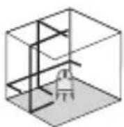
AutoCross-Laser 3C
1H 2V 1D
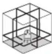
AutoCross-Laser 7C
3H 4V 1D
1nserção das pilhas
natural_image
Pure electrical circuit lines without any symbolsAutoCross-Laser
7C
natural_image
Pure electrical circuit lines without any symbolsAutoCross-Laser 2C AutoCross-Laser 3C
3 Posicionar as linhas de laser

natural_image
Pure electrical circuit lines without any symbolsAutoCross-Laser
7C
natural_image
Pure electrical circuit lines without any symbolsAutoCross-Laser 2C AutoCross-Laser 3C

natural_image
Interior sketch of a modern bathroom with sink, bathtub, and camera rig (no text or symbols)SERVICE

Umarex GmbH & Co KG
- Laserliner -

- AutoCross-Laser 2C AutoCross-Laser 3C
- Function / Application
- General safety instructions
- Special product features
- Number and direction of the lasers
- AutoCross-Laser 2C
- AutoCross-Laser 4C
- AutoCross-Laser 3C
- AutoCross-Laser 7C
- 1Inserting the batteries
- AutoCross-Laser 4C AutoCross-Laser 7C
- 2Horizontal and vertical levelling
- B Positioning laser lines
- Hand receiver mode
- Optional: Working with the laser receiver RX
- Preparing the calibration check:
- Performing the calibration check:
- Checking the vertical line:
- Checking the horizontal line:
- EU directives and disposal
- 1nserção das pilhas
- Posicionar as linhas de laser
- Umarex GmbH & Co KG
Brand : Laserliner
Model : AutoCrossLaser 3C Plus
Category : Hand tool