
RM 650 VE - Lawn mower STIHL - Free user manual and instructions
Find the device manual for free RM 650 VE STIHL in PDF.
| Product Type | Self-propelled lawn mower |
| Brand and Model | STIHL RM 650 VE |
| Power Source | Unleaded gasoline, 0.9 L tank |
| Engine | 4-stroke, EVC 300 E, 166 cm³, electric start (lithium-ion battery) |
| Cutting width | 48 cm |
| Cutting height | 25 to 85 mm, central continuous adjustment across 7 levels |
| Grass catcher capacity | 70 L |
| Dimensions (L × W × H) | 167 cm × 52 cm × 112 cm |
| Weight | 44 kg |
| Drive | Rear-wheel drive, Vario transmission (continuously adjustable speed 2.6–4.6 km/h) |
| Blade Clutch/Brake (BBC) | No (VE model without BBC; blade stops with engine) |
| Safety | Engine cutoff bar, engine and blade stop in <3 s, protection against unintentional restart |
| Guaranteed sound level | 96 dB(A) |
| Hand/arm vibrations | 3.00 m/s² (uncertainty 1.50 m/s²) |
| Battery | Lithium-ion, 1 battery supplied with charger, not rechargeable on the mower |
| Use options | Bagging, rear discharge, mulching (with mulching plug provided) |
| Maintenance and cleaning | Clean after each use; do not use high-pressure cleaner; oil and air filter change according to engine; annual maintenance recommended |
| Common replacement parts | Cutting blade (ref. 6364 702 0100), fixing screw (ref. 90083199075), lock washer (ref. 00007026600) |
| Warranty | STIHL manufacturer warranty according to general terms and conditions |
Frequently Asked Questions - RM 650 VE STIHL
User questions about RM 650 VE STIHL
0 question about this device. Answer the ones you know or ask your own.
Ask a new question about this device
Download the instructions for your Lawn mower in PDF format for free! Find your manual RM 650 VE - STIHL and take your electronic device back in hand. On this page are published all the documents necessary for the use of your device. RM 650 VE by STIHL.
USER MANUAL RM 650 VE STIHL
STIHL RM 650 T, RM 650 V, RM 650 VE, RM 650 VS RM 655 RS, RM 655 V, RM 655 VS, RM 655 YS
STIHL
DE Gebrauchsanleitung
EN Instruction manual
FR Manuel d'utilisation
NL Gebruiksaanwijzing
IT Istruzioni per l'uso
ES Manual de instrucciones
PT Manual de'utilisation
NO Bruksanvisning
SV Bruksanvising
FI Käyttoopaas
DA Betjeningsvejledning
PL Instrukcja obstrugi
SL Navodila za uporabo
SK Návod na obsluhu
TR Kullanim kilavuzu
RM 650.0 T RM 650.0 V RM 650.0 VS RM 650.1 VE RM 655.0 V RM 655.0 YS RM 655.1 RS RM 655.1 VS
B


1


(RM 650 VS, RM 655 RS,
RM 655 VS, RM 655 YS) 33
RM 650 VS, RM 655 RS, RM 655 VS,
RM 655 RS, RM 655 VS,
RM 650 VS, RM 655 YS:
J Akku (RM 650 VE) 1
RM650T, RM650V, RM650VE, RM650VS, RM655V, RM655VS, RM655YS:
RM650T, RM650V, RM650VE, RM650VS;
A>8mm
RM 655 RS, RM 655 V, RM 655 VS, RM 655 YS:
A>1 mm
Messung gemäß 2000/14/EG / S.I.
2001/1701:
Garantier Schall
RM 655.1 RS, RM 655.0 V, RM 655.1 VS, RM 655.0 YS:
Messung gemäß 2000/14/EG / S.I.
2001/1701:
Garantierer Schall
Thank you for choosing STIHL. We develop and manufacture our quality products to meet our customers' requirements. The products are designed for reliability even under extreme conditions.
STIHL also stands for premium service quality. Our specialist dealers guarantee competent advice and instruction as well as comprehensive service support.
We thank you for your confidence in us and hope you will enjoy working with your STIHL product.

Dr. Nikolas Stihl
IMPORTANT: READ BEFORE USE AND KEEP IN A SAFE PLACE.
1. Table of contents
Notes on the instruction manual 44
General 44
Instructions for reading the instruction manual 44
Lawn mower with blade brake clutch, BBC 45
Machine overview 45
For your safety 45
General 45
Refilling the tank - handling petrol 46
Battery and charger 47
Clothing and equipment 47
Transporting the machine 47
Before operation 48
During operation 48
Maintenance and repairs 50
Storage for prolonged periods without operation 51
Disposal 51
Description of symbols 52
Standard equipment 53
Preparing the machine for operation 53
General 53
Assembling the handlebar 53
Attaching and detaching the recoil starter rope 53
Installing the grass catcher box 54
Removing and inserting the mulch insert 54
Fuel and engine oil 54
Controls 54
General 54
Controls on the handlebar 54
Adjusting the handlebar 55
Central cutting height adjustment 55
Battery and charger (RM 650 VE) 55
Level indicator 55
Attaching and detaching the grass
catcher box 56
Safety devices 56
Safety devices 56
Motorstop lever 56
Blade brake clutch (BBC) 56
Notes on working with the machine 56
Working area for operator 56
Lawn mower with lawn roller 57
Applications 57
How should mulching be performed? 57
Operating the machine 57
Checking the blade brake clutch 57
Starting the engine (RM 650 T, RM 650 V, RM 655 V) 57
Starting the engine (RM 650 VE) 58
Stopping the engine (RM 650 T, RM 650 V, RM 650 VE, RM 655 V) 58
Starting the engine (RM 650 VS, RM 655 RS, RM 655 VS, RM 655 YS) 58
Engaging the mowing blade (RM 650 VS, RM 655 RS, RM 655 VS, RM 655 YS) 58
Disengaging the mowing blade (RM 650 VS, RM 655 RS, RM 655 VS, RM 655 YS) 58
Stopping the engine (RM 650 VS, RM 655 RS, RM 655 VS, RM 655 YS) 58
Self-propulsion 58
Emptying the grass catcher box 59
Maintenance 59
General 59
Cleaning the machine 59
Checking blade wear 60
Removing and installing the blade 60
Sharpening the mowing blade 61
Engine 61
Battery and charger maintenance 61
Wheels and gearbox 61
Lawn roller maintenance 61
Blade brake clutch (RM 650 VS,
RM 655 RS, RM 655 VS,
RM 655 YS) 61
Adjusting the self-propulsion cable (RM 655 YS) 61
Checking skirting protector wear 62
Storage and periods of inoperation (winter break)
Transport 62
Transport 62
Environmental protection 63
Minimising wear and preventing damage 63
Standard spare parts 64
Declaration of conformity 64
EU declaration of conformity - STIHL RM 650.0 T/V/VS,
RM 650.1 VE, RM 655.0 V/YS,
RM 655.1 RS/VS lawn mower
UKCA-Declaration of Conformity
STIHL RM 650.0 T, RM 650.0 V,
RM 655.0 V, RM 655.1 RS, RM
655.1 VS Lawn Mower
Technical specifications 65
REACH 68
Troubleshooting 68
Service schedule 70
Handover confirmation 70
Service confirmation 70
2. Notes on the instruction manual
2.1 General
This instruction manual constitutes original manufacturer's instructions in the sense of EC Directive 2006/42/EC.
STIHL is continually striving to further develop its range of products; we therefore reserve the right to make alterations to the form, technical specifications and equipment level of our standard equipment.
For this reason, the information and illustrations in this manual are subject to alterations.
This instruction manual may describe models that are not available in all countries.
This instruction manual is protected by copyright. All rights reserved, especially the right of reproduction, translation and processing using electronic systems.
2.2 Instructions for reading the instruction manual
Illustrations and texts describe specific operating steps.
All symbols which are affixed to the machine are explained in this instruction manual.
Viewing direction:
Viewing direction when "left" and "right" are used in the instruction manual:
the user is standing behind the machine and is looking forwards in the direction of travel.
Section reference:
References to relevant sections and subsections for further descriptions are made using arrows. The following example shows a reference to a section: ( 5.)
Designation of text passages:
The instructions described can be identified as in the following examples.
Operating steps which require intervention on the part of the user:
- Release bolt (1) using a screwdriver, operate lever (2)...
General lists:
- Use of the product for sporting or competitive events
Texts with added significance:
Text passages with added significance are identified using the symbols described below in order to especially emphasise them in the instruction manual:

Danger
Risk of accident and severe injury to persons. A certain type of behaviour is necessary or must be avoided.

Warning
Risk of injury to persons. A certain type of behaviour prevents possible or probable injuries.

Caution
Minor injuries or material damage can be prevented by a certain type of behaviour.

Note
Information for better use of the machine and in order to avoid possible operating errors.
Texts relating to illustrations:
Illustrations relating to use of the machine can be found in the front of this instruction manual.
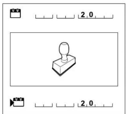
The camera symbol serves to link the figures on the illustration pages with the corresponding text passages in the instruction manual.

3. Lawn mower with blade brake clutch, BBC
Models RM 650 VS, RM 655 VS, RM 655 YS, RM 655 RS are equipped with a blade brake clutch (BBC).
As with all modern lawn mowers, the blade comes to a stop within a short time as soon as the handlebar is released. However, thanks to the BBC system, the engine continues to run. This function allows the user to use the mower's self-propulsion after the blade has stopped. Moreover, the grass catcher box can be emptied, for example, without having to start the engine again.

Risk of injury!
Never reach into the working area of the blade when the engine is running.
Stop the engine, allow the blade to come to a complete standstill and detach the spark plug socket before touching the blade.
In order to prevent injuries or damage to the machine, ensure that you are familiar with operation of the BBC system prior to
initial use.
Note the section "Blade brake clutch
(BBC)".( 11.)
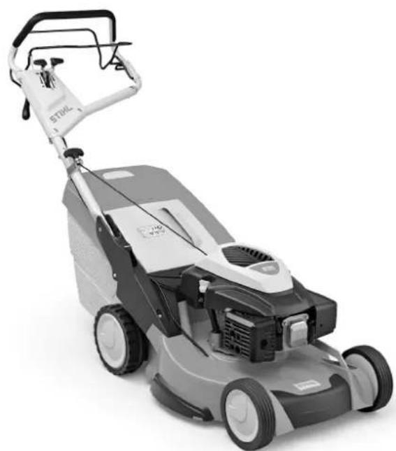
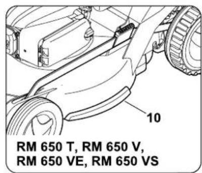
4. Machine overview

1 Upper handlebar with controls ( 9.2)
2Recoil starter rope
3 Handlebar bracket
4 Handlebar detent lever
5 Engine
6 Housing
7 Spark plug socket
8 Carrying handle
9 Replaceable skirting protector (RM 655 RS, RM 655 V, RM 655 VS, RM 655 YS)
10 Integrated skirting protector (RM 650 T, RM 650 V, RM 650 VS, RM 650 VE)
11 Cutting height indicator
12 Cutting height adjustment detent lever
13 Discharge flap
14 Grass catcher box
15 Level indicator
16 Rating plate with machine number
17 Lawn roller (RM 655 RS)
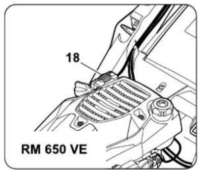
18 Battery (RM 650 VE)
5. For your safety
5.1 General

These safety regulations must be observed when working with the machine.

Read the entire instruction manual before using the machine for the first time. Keep the instruction manual in a safe
place for future reference.
Observe the operating and maintenance instructions contained in the separate engine instruction manual.
These safety precautions are essential for your safety, however the list is not exhaustive. Always use the machine in a reasonable and responsible manner and be aware that the user is responsible for accidents involving third parties or their property.
Make sure that you are familiar with the controls and use of the machine.
The machine must only be used by persons who have read the instruction manual and are familiar with operation of the machine. The user should seek expert and practical instruction prior to initial operation. The user must receive instruction on safe use of the machine from the vendor or another expert.
During this instruction, the user should be made aware that the utmost care and concentration are required for working with the machine.
Residual risks persist even if you operate this machine according to the instructions.

Risk of death from suffocation!
Packaging material is not a toy danger of suffocation! Keep packaging material away from children.
Only give or lend the machine, including any accessories, to persons who are familiar with this model and how to operate it. The instruction manual forms part of the machine and must always be provided to persons borrowing it.
The machine must only be operated by persons who are well rested and in good physical and mental condition. If your health is impaired, you should consult your doctor to determine whether working with the machine is possible. The machine should not be operated after the consumption of alcohol, drugs or medications which impair reactions.
Make sure that the user is physically, sensorily and mentally capable of operating the machine and working with it. If the user is physically, sensorily or mentally impaired, the machine must only be used under supervision or following instruction by a responsible person.
Make sure that the user is of legal age or being trained under supervision in a profession in accordance with national regulations.
Caution - risk of accident!
The lawn mower is only intended for mowing lawns. Its use for other purposes is not permitted and may be dangerous or result in damage to the machine.
Due to the physical danger to the user, the lawn mower must not be used for the following applications (incomplete list):
-
For trimming bushes, hedges and shrubs.
-
For cutting creepers.
- For tending lawn roofs and balcony boxes.
- For shredding or chopping tree or hedge cuttings.
- For clearing paths (vacuuming, blowing).
- For levelling earth mounds, e.g. mole hills.
- For transporting clippings, except in the grass catcher box intended for this purpose.
For safety reasons, any modification to the machine, except the proper installation of accessories approved by STIHL, is forbidden and results in voiding of the warranty cover. Information regarding approved accessories can be obtained from your STIHL specialist dealer.
In particular, any tampering with the machine which increases the power output or speed of the engine or motor is forbidden.
It is not permitted to transport objects, animals or persons, particularly children, on the machine.
Particular care is required during use in public green spaces, parks, sports fields, along roads and in agricultural and forestry businesses.

Caution! Danger to health due to vibrations. Excessive exposure to vibrations can result in damage to the
cardiovascular or nervous system, particularly in persons with cardiovascular problems. Please consult a physician if you experience symptoms that may have been caused by vibrational loads.
Symptoms of this kind principally affect the fingers, hands or wrists and include (incomplete list):
- numbness,
-pain, - muscular weakness,
- skin discolouration,
- unpleasant tingling sensation.
Hold the handlebar tightly, but not tensed, with both hands in the designated locations during operation.
Plan your working times so that more severe physical strains over a longer period are avoided.
Only release the machine if it is on a level surface and cannot roll away by itself.
5.2 Refilling the tank - handling petrol

Danger to life!
Petrol is poisonous and extremely inflammable.
Petrol must only be stored in appropriate, tested containers (canisters). Always screw on the fuel tank and canister caps properly and tightly. Defective caps must be replaced for safety reasons.
Never use beverage bottles or similar for disposal or storage of fuels and lubricants. Persons, particularly children, could be tempted to drink out of them.

Keep petrol away from sparks, naked flames, pilot lights, heat sources, and other ignition sources. Do not smoke!
Refill the tank out-of-doors and do not smoke during refilling.
Before refilling the tank, stop the engine and allow it to cool.
Refilling with petrol must be performed before the engine is started. When the engine is running or is hot, the tank cap must not be removed and the tank must not be refilled with petrol.
Do not overfill the fuel tank!
To give the fuel room to expand, never fill the fuel tank past the lower edge of the filler neck. Observe the additional instructions in the engine instruction manual.


If petrol is spilled, the engine must only be started after the petrol-contaminated area has been cleaned. All attempts at starting must be avoided until the petrol fumes have dispersed (wipe dry).
Any spilt fuel must be wiped up immediately.
Clothing must be changed if it comes into contact with petrol.
Never store the machine with petrol in the tank inside a building. The resulting petrol fumes could come into contact with naked flames or sparks and could be ignited.
If it is necessary to drain the tank, this must be done out of doors.
5.3 Battery and charger
Read the engine instruction manual and keep it in a safe place. This instruction manual describes how to safely use the battery and charger.
Only use genuine batteries and genuine chargers.
Protect the battery and charger against rain and moisture and do not drop.
Do not use a damaged or deformed battery or a damaged charger. In particular check the power cable of the charger. Never use a charger with a damaged power cable.
Never dismantle or attempt to repair a battery or charger. A defective battery or charger must be replaced.
Only connect the charger to a power supply that is protected by means of a residual current-operated protective device with a maximum release current of 30mA . Your electrician can provide further information.
Keep the unused battery away from metal objects (e.g. nails, coins, jewellery). Never short circuit battery connections, do not use metal containers to transport batteries.
Fluid may escape from the battery due to improper use - avoid contact! In the case of inadvertent contact, rinse with water. Seek medical attention if the fluid contacts the eyes. Escaping battery fluid can cause skin irritation and burns.
For further safety instructions, see http://www.stihl.com/safety-data-sheets
5.4 Clothing and equipment

Always wear sturdy footwear with high-grip soles when working. Never work barefoot sample, in sandals.

Also always wear sturdy gloves and tie up and secure long hair (headscarf, cap, etc.) when performing maintenance and work or when transporting the

Wear suitable safety glasses when sharpening the mowing blade.
Always wear long trousers and tight-fitting clothing when operating the machine.
Never wear loose clothes which may become caught on moving parts (control levers) – do not wear jewellery, ties or scarves.

Noise is produced when working. Noise can damage the hearing.
Wear hearing protection.
5.5 Transporting the machine
Always wear gloves in order to prevent injuries due to sharp-edged and hot components.
Do not transport the machine with the engine running. Switch off the engine, let the blades come to a standstill and remove the spark plug socket prior to transport.
Only transport the machine once the engine has cooled down and with an empty fuel tank.
Use suitable loading aids (loading ramps, lifters).
Secure the machine and any machine components being transported (e.g. grass catcher box) on the load floor using fastening material of adequate size (belts, ropes, etc.).
Avoid contact with the mowing blade when lifting and carrying the machine.
Observe the information in the section "Transport". It describes how to lift and lash the machine. ( 15.)
When transporting the machine, always observe regional legislation, especially regarding load security and the transport of objects on load floors.
Do not leave the battery inside a vehicle and protect unused batteries against direct sunlight.
Lithium-ion batteries must be treated with special care during transport. In particular, short-circuit protection must be ensured. Transport the battery either in the original packaging or in a suitable non-metal transport container.
5.6 Before operation
Make sure that only persons who are familiar with the instruction manual are permitted to use the machine.
Remove the packaging material and transport locks before using the machine for the first time.
Check the fuel system (particularly visible parts such as e.g. tank, tank cap, hose connections) before operating the machine. In the event of any leaks or damage, do not start the engine - fire hazard!
Have the machine repaired by a specialist dealer prior to operation.
Observe the local regulations regarding permitted operating times for gardening power tools with combustion engines.
Carefully inspect the complete area on which the machine is to be used and remove any stones, sticks, wires, bones and other foreign objects which could be thrown up by the machine. Obstacles (e.g. tree stumps, roots) can be easily overlooked in long grass.
For this reason, mark all foreign objects (obstacles) which are hidden in the lawn and cannot be removed before commencing work with the machine.
All faulty, worn or damaged parts must be replaced before using the machine. Replace any illegible or damaged danger signs and warnings on the machine. Your STIHL specialist has a supply of replacement stickers and all the other spare parts.
Check secure seating of the spark plug socket on the spark plug before using the machine.
The machine must only be used in good operating condition. Before each use, check whether:
- The machine is properly assembled.
- The cutting tool and the entire cutting unit (mowing blade, fastening elements, mowing deck housing) are in good condition. In particular check for secure fastening, damage (notches or cracks) and wear. ( 14.3) , ( 14.12)
- The mulch insert is in good condition.
- The tank cap is properly attached.
The tank and fuel-carrying parts as well as the tank cap are in good condition. - The safety devices (e.g. motorstop lever, discharge flap, housing, handlebar, protective grille) are in good condition and working properly.
- The blade brake clutch is working properly. ( 13.1)
-
The grass catcher box is undamaged and correctly installed; a damaged grass catcher box must not be used.
The battery (RM 650 VE) is not damaged or deformed. -
The oil closure screw is properly attached.
Carry out any necessary work or consult a specialist dealer. STIHL recommends STIHL specialist dealers.
5.7 During operation

Keep other people out of the danger area. Never work when animals or people, particularly children, are in the danger area.
The switch and safety devices installed in the machine must not be removed or bypassed. In particular, never secure the motorstop lever or blade stop lever to the handlebar (e.g. by tying it).

Caution - risk of injury! Never put hands or feet on or underneath rotating parts. Never touch the rotating blade.
Always keep away from the discharge opening.
Always observe the safety distance provided by the handlebar. The handlebar must always be installed correctly and must not be modified. Never operate the machine with the handlebar folded down.
Never attach any objects to the handlebar (e.g. work clothing).
Only work during the day or with good artificial light.
Do not operate the machine in the rain or during thunder storms, particularly when there is a risk of lightning strike.
The risk of accidents is higher if the ground is damp due to increased danger of slipping.
Particular caution should be exercised
during working in order to prevent slipping. If possible, avoid using the machine when the ground is damp.
Exhaust gases:

Danger to life through poisoning! In the case of nausea, headache, impaired vision (e.g. decreasing field of view) hearing disorder, dizziness, decreasing power of concentration, stop working immediately. These symptoms may be caused by excessively high exhaust gas concentrations.

The machine generates poisonous exhaust gases when the engine is running. The gases contain poisonous
carbon monoxide, a colourless and odourless gas, as well as other pollutants. The engine must never be operated in closed or poorly ventilated spaces.
Starting:
Exercise care when starting the machine and observe the instructions contained in the section entitled "Operating the machine" ( 13) . Starting the machine in accordance with these instructions reduces the risk of injury.
Risk of injury!
If the starter rope recoils at speed, the hand and arm will be pulled towards the engine faster than the starter rope can be released. This kickback can result in broken bones, crush injuries and sprains.
Keep your feet a safe distance from the cutting tool when starting the machine.
The machine must not be tilted during start-up.
The self-propulsion lever must not be actuated when starting the engine.
RM 650 VS, RM 655 RS, RM 655 VS, RM 655 YS: The mowing blade must not be engaged when starting the engine.
Do not start the engine if the discharge chute is not covered by the discharge flap or the grass catcher box.
Working on slopes:
Always work across and back on slopes, never up and down.
If the user loses control when mowing up and down, there is a risk of being run over by the machine.
Be particularly careful when changing direction on a slope.
Always ensure good stability on slopes and avoid mowing on excessively steep slopes.
For safety reasons, the machine must not be used on slopes with an inclination of more than 25^ (46.6%) . Risk of injury! A slope inclination of 25^ corresponds to a vertical height increase of 46.6~cm for a 100~cm horizontal distance.
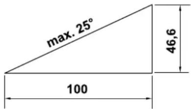
In order to ensure an adequate oil supply for the engine, the information in the accompanying engine instruction manual must be additionally observed when using the machine on slopes.
Working:

Risk of injury!
Never place your hands or feet above, underneath or on rotating parts.

Do not try to examine the blade while the lawn mower is operating. Never open the discharge flap and/or remove
the grass catcher box when the mowing blade is running. Rotating blades can cause injury.
Only operate the machine at walking speed - never run when working with the machine. Working quickly with the machine increases the risk of injury due to stumbling, slipping, etc.
Only guide the machine using the handlebar - never use the levers to move the lawn mower. ( 12.1)
Be particularly careful when turning the machine around or pulling it towards you.
Risk of stumbling!
Use the machine with great care when working near slopes, terraces, ditches and embankments. In particular, ensure that you maintain sufficient distance to such danger areas.
Objects hidden in the turf (lawn sprinkler systems, posts, water valves, foundations, electrical wires, etc.) must be avoided. Never run over any such foreign objects.

Beware of the cutting tool running on for several seconds before coming to a standstill.
STOP Switch off the engine, allow the work tool to come to a complete standstill, detach the spark plug socket and additionally remove the battery (with RM 650 VE),
before leaving the machine unattended,
before re-filling the tank. Allow the engine to cool down before filling the tank. Fire hazard!
- before remedying blockages, including those in the discharge chute,
before lifting or carrying the machine,
before transporting the machine,
before carrying out any work on the mowing blade,
before checking or cleaning the machine or before carrying out any other work (e.g. folding down the handlebar, installing and removing the mulching key) on it,
- after hitting a foreign object or if the lawn mower begins to vibrate excessively. In these cases check the machine, in particular the cutting unit (blade, blade shaft, blade fastening) for damage and carry out the necessary repairs before restarting and working with the machine.

Risk of injury!
Strong vibration is normally an indication of a fault. In particular, the lawn mower must not be operated with a damaged or bent crankshaft or mowing blade. If you do not have the appropriate expertise, have the necessary repairs carried out by a specialist dealer (STIHL recommends STIHL specialist dealers).
Stop the engine and disengage the mowing blade:
- When pushing the machine to and from the area to be worked.
- Before pushing the machine onto an area not covered with grass.
- Before opening the discharge flap or removing the grass catcher box.
- When the machine has to be tilted for transportation.
- Before adjusting the cutting height.
5.8 Maintenance and repairs
Before beginning cleaning, adjustment, repair and maintenance operations:
- Park the machine on firm and level ground
- Stop the engine and allow it to cool down
- Detach the spark plug socket.
Caution - risk of injury!
Keep the spark plug socket away from the spark plug; an inadvertent ignition spark may result in fires or electric shocks.
Inadvertent contact between the spark plug and the spark plug socket may result in unwanted starting of the engine.
RM 650 VE: Additionally remove the battery.
Allow the machine to cool down before working on or around the engine, exhaust manifold or muffler in particular. Temperatures of 80^ and above can be reached. Danger of burns!

Risk of injury due to the mowing blade!
Pulling the recoil starter rope starts the work tool rotating. Always ensure sufficient distance between the mowing blade and your body, particularly your hands and feet, when you pull the recoil starter rope.
Direct contact with engine oil can be dangerous. Engine oil must not be spilled. STIHL recommends leaving the task of topping up engine oil or performing engine oil changes to a STIHL specialist dealer.
Cleaning:
The complete machine must be cleaned thoroughly following use. ( 14.2)
Empty the fuel tank (e.g. by running it empty) before placing the machine in the cleaning position.
Remove accumulated clipping deposits using a stick. Clean the underside of the mower with water and a brush.
Never use high-pressure cleaners and do not clean the machine under running water (e.g. using a garden hose).
Do not use aggressive cleaning agents. These can damage plastics and metals, impairing the safe operation of your STIHL machine.
In order to prevent fire hazards, keep the area around the air vents, cooling ribs and the area of the exhaust free from e.g. grass, straw, moss, leaves or escaping grease.
Maintenance operations:
Only maintenance operations described in this instruction manual may be carried out. Have all other work performed by a specialist dealer.
If you do not have the necessary expertise or auxiliary equipment, please always contact a specialist dealer.
STIHL recommends that you have maintenance operations and repairs performed exclusively by a STIHL specialist dealer.
STIHL specialist dealers regularly attend training courses and are provided with technical information.
Only use tools, accessories or attachments approved for this machine by STIHL or technically identical parts. Otherwise, there may be a risk of accidents resulting in personal injury or damage to the machine. If you have any questions, please consult a specialist dealer.
The characteristics of original STIHL tools, accessories and spare parts are optimally adapted to the machine and the user's requirements. Genuine STIHL spare parts can be recognised by the STIHL spare parts number, by the STIHL lettering and, if present, by the STIHL spare parts symbol. On smaller parts, only the symbol may be present.
For safety reasons, fuel-carrying components (fuel line, fuel cock, fuel tank, tank cap, connections, etc.) must be checked regularly for damage and leaks and replaced by a technician if necessary (STIHL recommends STIHL specialist dealers).
Always keep warning and information stickers clean and readable. Damaged or missing stickers must be replaced by new, original plates from your STIHL specialist dealer. If a component is replaced with a new component, ensure that the new component is provided with the same stickers.
Only perform work on the cutting unit when wearing thick work gloves and exercising extreme care.
Ensure that all nuts, pins and screws (in particular the blade fastening screw) are securely tightened so that the machine is in a safe operating condition.
Replace damaged exhaust silencers and guard plates.
Check the complete machine and the grass catcher box for wear or damage on a regular basis, particularly before extended periods when the machine is not in use (e.g. over winter). For safety reasons, worn or damaged parts must be replaced immediately to ensure that the machine is always in a safe operating condition.
Never alter the basic setting of the engine or run at excessive engine speeds.
Components or guards that are removed for maintenance operations must be properly reinstalled immediately.
5.9 Storage for prolonged periods without operation
Allow the engine to cool before storing the machine in an enclosed space.
Ensure that the machine is protected from unauthorised use (e.g. by children).
Store the machine with empty fuel tank and the fuel reserve in a lockable and well-ventilated room.
Never store the machine with petrol in the tank inside a building. The resulting petrol fumes could come into contact with naked flames or sparks and could be ignited.
If the tank has to be emptied (e.g. to store the machine before the winter break), this should only be done out of doors (e.g. by running the tank empty).
Thoroughly clean the machine before storage (e.g. winter break).
Store the machine on a suitable surface and only standing on its wheels - secure it against rolling away.
Only store the machine with the spark plug socket disconnected.
RM 650 VE: Before storing the machine, remove the battery and store it separately from the machine as well as protected from unauthorised use (e.g. by children).
Store the machine in good operational condition.
Allow the machine to cool down completely before covering it.
Store the machine on a level surface so that it cannot unintentionally roll away.
5.10 Disposal
Waste products such as used engine oil or fuel, used lubricants, filters, batteries and similar wearing parts can be harmful to people, animals and the environment, and must consequently be disposed of properly.
Consult your recycling centre or your specialist dealer for information on the proper disposal of waste products. STIHL recommends STIHL specialist dealers.
Ensure that old machines are properly disposed of. Render the machine unusable prior to disposal. In order to prevent accidents, remove the ignition lead, empty the fuel tank and drain the engine oil in particular.
The battery must be disposed of separately from the machine. Ensure that batteries are disposed of safely and in an environmentally friendly manner.
Risk of injury due to the mowing blade! Always store an old lawn mower in a safe place prior to scrapping. Ensure that the machine and particularly the mowing blade are kept out of the reach of children.
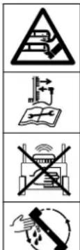
6. Description of symbols
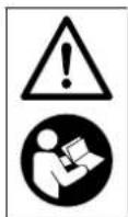
Attention!
Read the instruction manual and follow the safety instructions before initial use.
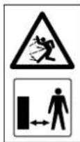
Risk of injury!
Keep other people out of the danger area.
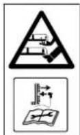
Caution!
Keep your hands and feet away from the blades.
Detach the spark plug socket before performing work on the cutting tool or maintenance and cleaning work.
RM 650 VS, RM 655 RS, RM 655 VS, RM 655 YS:

Caution - risk of injury!
Never reach into the working area of the blade when the engine is running.
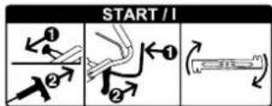
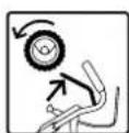
Starting the engine, engaging the mowing blade
Disengaging the mowing blade.
Switching on self-propulsion
Throttle setting
Choke position (only RM 655 YS) Press throttle lever forward to the stop
Start position maximum speed
Stop position-stop the engine, pull the throttle lever back to the stop


RM650T, RM650V, RM655V:
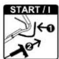
Starting the engine

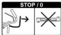
Stopping the engine

Switching on self-propulsion
RM 650 VE:
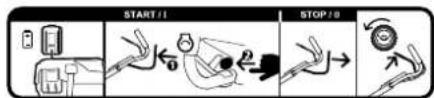
START: Fit the battery, start the engine.
STOP: Stop the engine.
Engaging self-propulsion
RM 650 V, RM 650 VE, RM 650 VS, RM 655 V, RM 655 VS, RM 655 YS:
Setting the driving speed
Fast - Push driving speed lever forward
Slow - Pull driving speed lever back

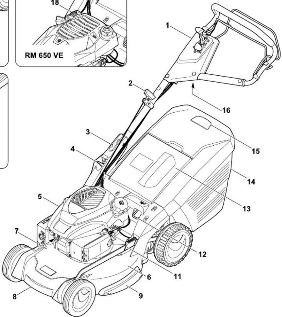
7. Standard equipment

Item Designation Qty.
A Basic unit 1
B Lower part of grass catcher box 1
C Upper part of grass catcher box 1
D Pin 2
E Sleeve 1
F Bolt 1
G Washer 2
H Nut 1
I Mulch insert - installed in discharge chute (RM 650 T, RM 650 V, RM 650 VE, RM 650 VS, RM 655 V, RM 655 VS, RM 655 YS)
J Battery (RM 650 VE) 1
K Charger (RM 650 VE) 1
- Instruction Manual 1
Engine Instruction Manual 1
8. Preparing the machine for operation
8.1 General

Risk of injury!
Observe the safety instructions in the section "For your safety" ( 5) .
- Place the machine on level and firm ground when performing all the operations described.
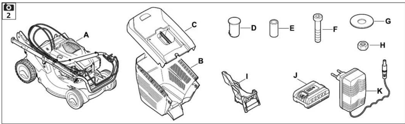
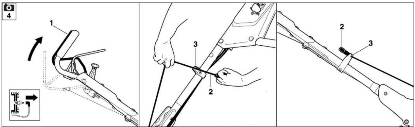
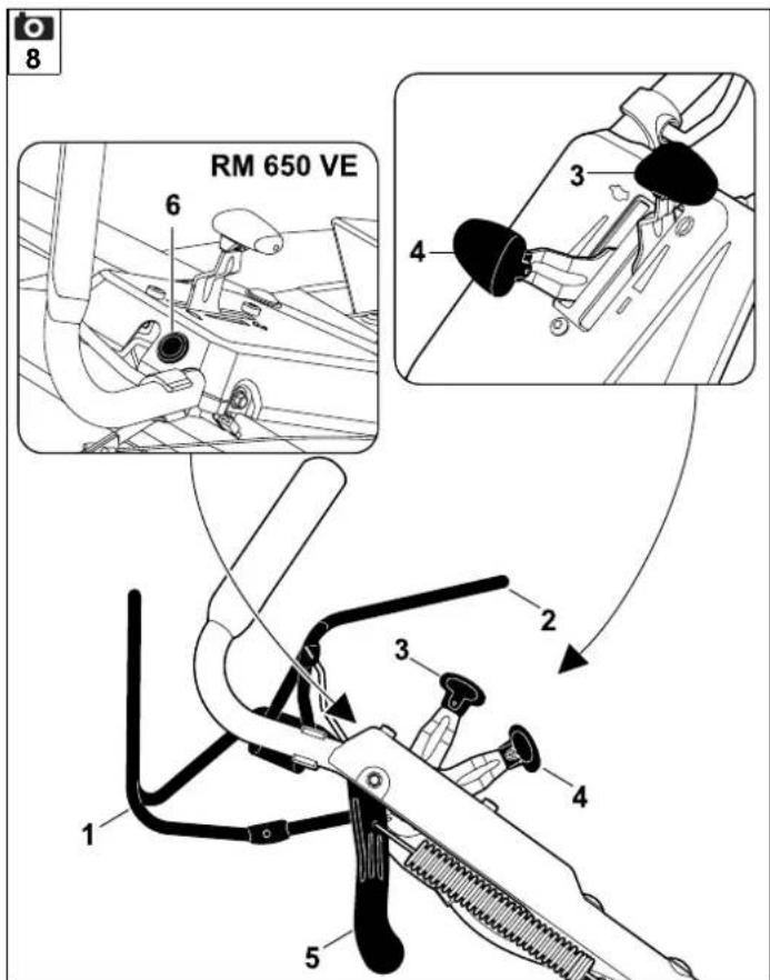
8.2 Assembling the handlebar
- Insert sleeve (E) in the bore on handlebar (1).
- Fit two washers (G) with the convex side facing inwards onto the sleeve.
- Hold sleeve (E) and washers (G) and insert together with handlebar (1) into handlebar console (2) from below.
- 4 Fold handlebar (1) upwards until the bores in the handlebar console and sleeve (E) are aligned.
- Place nut (H) in the handlebar console recess and hold.
- Insert bolt (F) from the outside inwards through the bores in handlebar console (2) and the sleeve. Tighten bolt (F). Tightening torque: 18 - 22 Nm
- Fold down the handlebar into the transport position. (⇒ 9.3)
Attaching cables:

Avoid damage to the machine!
Never kink cables or damage cable covers.
- Insert all cables (3) into the guide on handlebar console (4). To do this, slightly bend the cables - without kinking them - and insert into guide (4) as shown.
RM 650 VS, RM 655 RS, RM 655 VS, RM 655 YS:
Place the BBC cable ( = 7mm) in guide (4) first. - Insert all cables (3) into cable guide (5).
- Fold up the handlebar into the working position. (⇒ 9.3)

RM 655 YS:
Adjust the self-propulsion cable. ( 14.11)
8.3 Attaching and detaching the recoil starter rope

RM 650 VE: The engine does not have a recoil starter rope.
Attaching:
- Detach the spark plug socket from the engine.
- RM650T, RM650V, RM655V Press motorstop lever (1) to the handlebar and hold.
- Slowly pull out recoil starter rope (2) and attach it to rope guide (3).
- Slowly release recoil starter rope (2) and motorstop lever (1).
- Connect the spark plug socket.
Detaching:
- Detach the spark plug socket from the engine.
- RM650T, RM650V, RM655V Press motorstop lever (1) to the handlebar and hold.
- Slowly pull out recoil starter rope (2) and detach it from rope guide (3).
- Slowly return recoil starter rope (2) and release motorstop lever (1).
- Connect the spark plug socket.
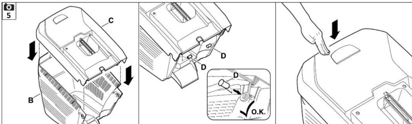
8.4 Installing the grass catcher box

- Fit upper part of grass catcher box (C) onto lower part of grass catcher box (B).
- Push pin (D) through bores provided from inside.
- Allow the upper part of the grass catcher box to engage in the lower part of the grass catcher box using slight pressure.
-
Attach the grass catcher box. ( 9.7)
-
Close the discharge flap and attach the grass catcher box if necessary.
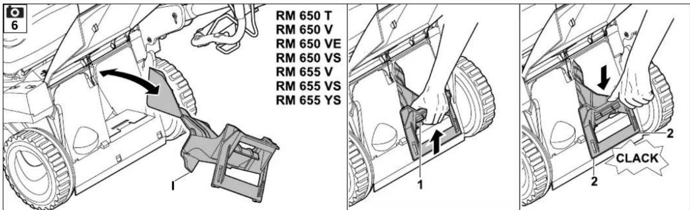
Inserting the mulch insert:
- Open the discharge flap and hold it open. Detach the grass catcher box if necessary. ( 9.7)
- Insert mulch insert (1) in the discharge chute diagonally from above as shown, turn to the horizontal position, press down and engage audibly with both retaining lugs (2) in the housing.
- Close the discharge flap.
9. Controls
9.1 General

Risk of injury!
Observe the safety instructions in the section "For your safety" (⇒ 5.).
- Place the machine on level and firm ground when performing all the operations described.
8.5 Removing and inserting the mulch insert

RM650T,RM650V,RM650VE,RM650VS,RM655V,RM655VS,
RM655YS:
The lawn mower is equipped with a mulch insert as standard. The mulch insert is installed in the discharge chute on delivery.
Avoid damage to the machine! Always keep the removed mulch insert in a safe place and never use for another purpose (e.g. as a wedge).
Only use the mulch insert in conjunction with the standard blade.
Removing the mulch insert:
- Open the discharge flap and hold it open.
- Lift detent catch (1) and pull mulch insert (I) diagonally upwards out of the discharge chute.
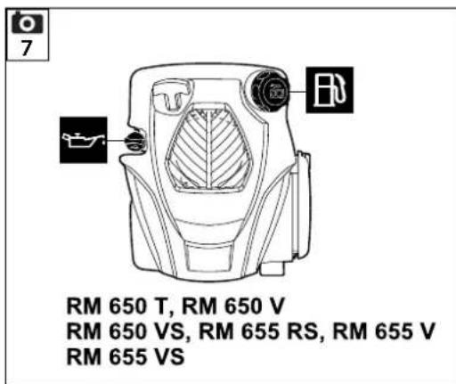
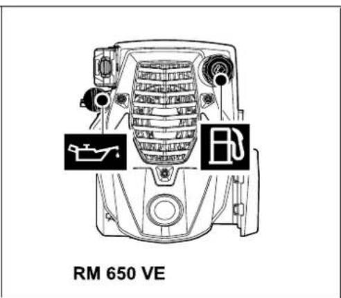
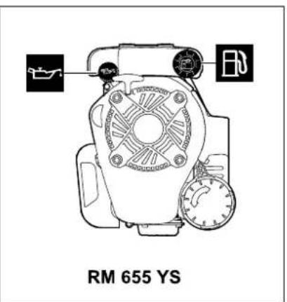
8.6 Fuel and engine oil
Avoid damage to the machine! Top up engine oil before starting for the first time. Use a suitable filling aid when topping up the engine oil and when refuelling (e.g. funnel).
Engine oil:
Please consult the engine instruction manual for the type of engine oil to be used and the oil capacity. Check the oil filling level at regular intervals (see engine instruction manual). Avoid exceeding or falling below the correct oil level. Screw on the oil tank cap properly prior to operating the engine.
Fuel:
Recommendation: Fresh good quality fuels, unleaded petrol.
Please consult the engine instruction manual for details on the fuel quality (octane rating).


9.2 Controls on the handlebar

1 Motorstop lever
(RM 650 T, RM 650 V, RM 650 VE, RM 655 V)
1 Blade stop lever
(RM 650 VS, RM 655 RS, RM 655 VS, RM 655 YS)
2 Self-propulsion lever
3 Throttle lever
(RM 650 VS, RM 655 RS, RM 655 VS, RM 655 YS)
4 Driving speed lever
(RM 650 V, RM 650 VS, RM 650 VE, RM 655 V, RM 655 VS, RM 655 YS)
5 Blade clutch lever
(RM 650 VS, RM 655 RS, RM 655 VS, RM 655 YS)
6 Start button
(RM 650 VE)
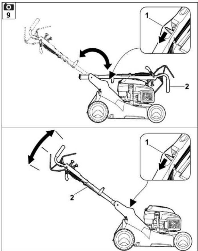
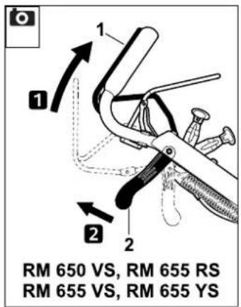
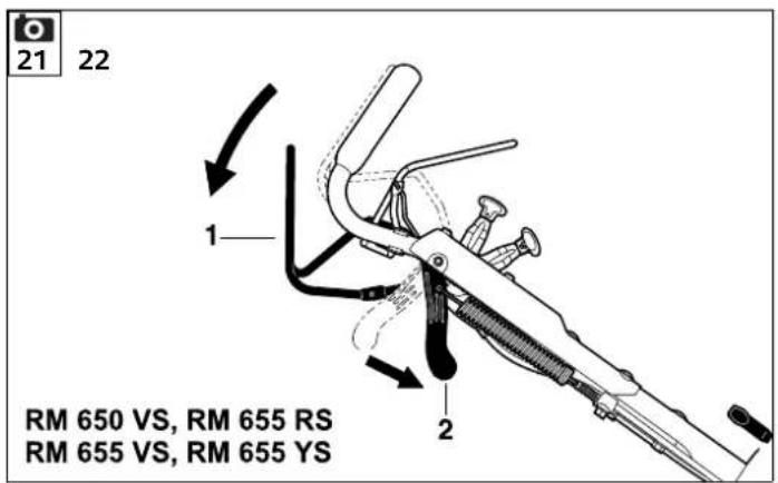
9.3 Adjusting the handlebar


Danger of pinching!
When actuating the detent lever, always hold the upper handlebar with one hand at its highest point. Never place your fingers between the handlebar and console (above and below the detent lever).
Transport position (for cleaning, for space-saving transport and for storage of the machine):
- Detach the recoil starter rope from the rope guide. ( 8.3)
- Hold the upper handlebar (2) with one hand at its highest point and lift (relieve load) slightly.
- Press the detent lever (1) downwards and hold.
- Fold down handlebar (2) forwards.
Working position:
- Fold the handlebar (2) up rearwards and ensure that the handlebar is fully engaged.
- Attach the recoil starter rope at the rope guide. (⇒ 8.3)
Height adjustment:
The handlebar can be adjusted to 3 positions:
- Hold the upper handlebar (2) with one hand at its highest point and lift (relieve load) slightly.
- Press the detent lever (1) downwards and hold.
-
Move the handlebar (2) into the required position.
-
Release the detent lever (1) and ensure that the handlebar is again fully engaged.
9.4 Central cutting height adjustment
RM 650 T, RM 650 V, RM 650 VE, RM 650 VS, RM 655 V, RM 655 VS, RM 655 YS:
Seven cutting heights can be set.
Level 1: 25 mm
Level 7: 85 mm
RM 655 RS:
Six cutting heights can be set.
Level 1:20 mm
Level 6:80 mm
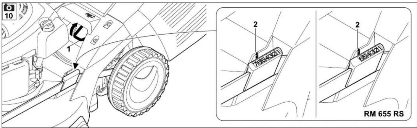
- Pull detent lever (1) upwards and hold in order to release the detent mechanism. Set the required cutting height by moving the machine upwards or downwards.
- The cutting height can be read on the cutting height indicator (2).
- Release detent lever (1) again and allow the height adjustment to engage.
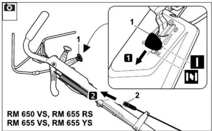
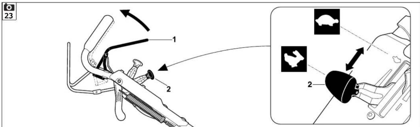
9.5 Battery and charger (RM 650 VE)
The lawn mower RM 650 VE is equipped with an electric starter. A lithium-ion battery is used as the starter battery. Instructions on how to use the battery and charger can be found in the supplied engine instruction manual.
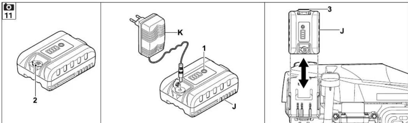
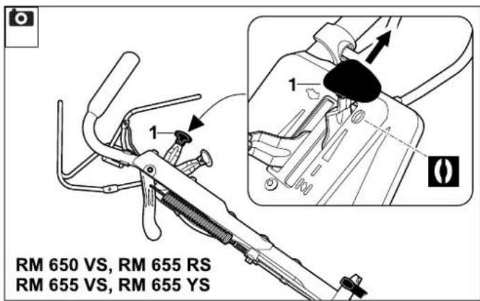
The battery must only be charged using the supplied charger; the battery is not recharged during operation of the lawn mower. Press button (1) on the battery to check the charge state.
Initial operation:
- Open protective cap (2) on the battery.
- Connect charger (K) to the mains power supply and charge battery (J) completely.
Removing and inserting the battery:
- Press release (3) and remove battery (J) from the engine by pulling it sideways and upwards and re-insert in the opposite direction.
9.6 Level indicator
The flow of air generated by the blade raises level indicator (1). The flow of air stops when the grass catcher box is full. If the flow of air is too low, level indicator (1) returns to its resting state. This is a prompt to empty the grass catcher box.
The functionality of the level indicator is restricted if the flow of air is impaired. External influences such as wet, dense or high grass, low cutting levels, contamination or the like can impair the flow of air and the functionality of the level indicator.
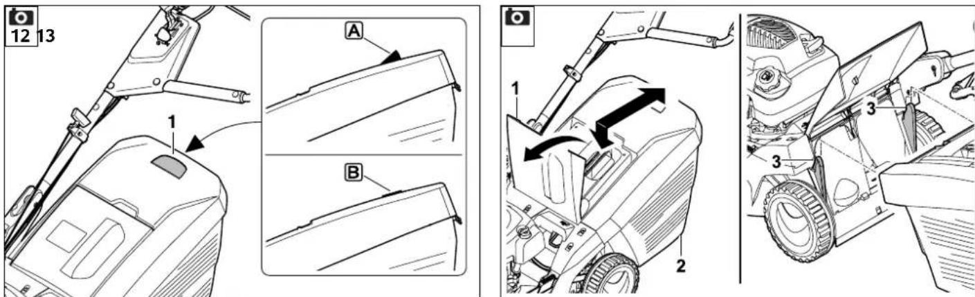
A Grass catcher box is being filled
Grass catcher box is filled
- Empty the filled grass catcher box ( 13.10) .
9.7 Attaching and detaching the grass catcher box

- Remove the mulch insert before attaching the grass catcher box. (⇒ 8.5)
Attaching:
- Open the discharge flap (1) and hold it open.
- Attach grass catcher box (2) to the locating lugs (3).
- Close discharge flap (1) again.
Detaching:
- Open the discharge flap (1) and hold it open.
- Lift grass catcher box (2), detach from the locating lugs (3) and remove.
- Close discharge flap (1) again manually.
10. Safety devices
The machine is equipped with several safety devices for safe operation and for the prevention of improper use.

Risk of injury!
If a safety device is found to be defective, the machine must not be operated. Consult a specialist dealer; STIHL recommends STIHL specialist dealers.
10.1 Safety devices
The lawn mower is equipped with safety devices, which prevent inadvertent contact with the mowing blade and with ejected clippings.
These include the housing, discharge flap, grass catcher box and correctly installed handlebar.
10.2 Motorstop lever
Models RM 650 T, RM 650 V, RM 650 VE, RM 655 V are equipped with a motorstop device.
The engine stops when motorstop lever (1) is released during running operation. The engine and blade come to a standstill within 3 seconds.

Risk of injury!
If the run-on time of the blade exceeds this delay, stop using the machine and take it to your specialist dealer.
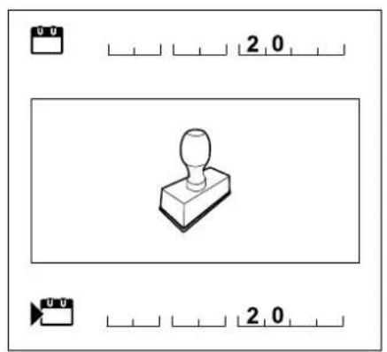
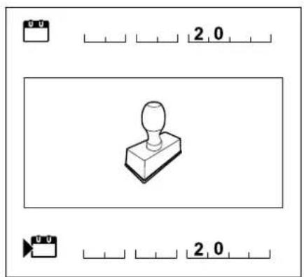
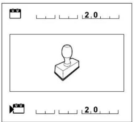
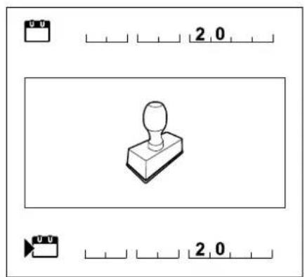
Measuring the run-on time
Following engine start-up, the blade rotates and a wind noise is audible. The run-on time corresponds to the duration of the wind noise after the engine stops. This can be measured using a stopwatch.
11. Blade brake clutch (BBC)
Models RM 650 VS, RM 655 RS, RM 655 VS, RM 655 YS are equipped with a blade brake clutch (BBC).

Risk of injury!
Operation of the blade brake clutch must be checked before each use. ( 13.1)
For safety reasons, the lever must never be disabled, e.g. by tying it to the handlebar.
Two-hand operation:
The mowing blade can only be engaged as follows with the engine running:
- Press blade stop lever (1) with one hand and, while keeping it pressed, pull blade clutch lever (5) upwards with the other hand and allow it to engage. ( 13.6)
Integrated blade run-down brake:
When the blade stop lever is released (or after releasing the handlebar), the mowing blade is disengaged and braked to a standstill within a maximum of 3 seconds, while the engine continues to run. ( 13.7)
12. Notes on working with the machine
A perfect, thick lawn is achieved by
- Mowing at low driving speeds.
-Mowing regularly and keeping the grass short.
Not cutting the lawn too short in hot, dry conditions as it will be burnt by the sun and become unsightly. - Using a sharp mowing blade - mowing blade should therefore be sharpened regularly (specialist dealer).
- Changing the cutting direction regularly.
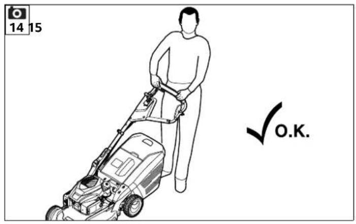
12.1 Working area for operator
- For safety reasons, the operator must stay within the working area behind the handlebar when starting the engine and when the engine is running. Always observe the safety distance provided by the handlebar.

- The lawn mower must only be operated by one person. Other persons must keep out of the danger area. ( 5.)
12.2 Lawn mower with lawn roller
The model RM 655 RS is equipped with a two-part drive roller on the rear axle.

This permits accurate mowing along lawn edges or around plants. The grass is also rolled in the direction of travel, creating a characteristic striped lawn pattern.
12.3 Applications
The lawn mower is equipped with a multiblade and can be used as a mulching mower or rear discharge mower as well as a grass collector.
To use the machine as a mulching mower, install the mulch insert. ( 8.5)
- For use as a rear discharge mower or grass collector (with grass catcher box), remove the mulch insert from the machine. ( 8.5)
12.4 How should mulching be performed?
Mulching is only possible with the models RM 650T, RM 650V, RM 650VE, RM 650VS, RM 655V, RM 655VS, RM 655 YS.
A cutting height between 4 and 7 should be selected for mulching, as this is the most suitable height for shredding the grass.
If the cutting height is too low, the mower housing may become clogged, resulting in blockage of the mowing blade
It is important to select the correct operating speed and cutting height for mulching to allow the mowing blade to achieve optimal grass shredding and a good cutting pattern.
In high grass, it is advisable to work in several stages and in the higher cutting height settings.
Mulching should not be performed when the grass is too high or wet.
13. Operating the machine
13.1 Checking the blade brake clutch
Operation of the blade brake clutch must be checked three times before starting work.
- Engage the mowing blade with the engine running. ( 13.6) A running mowing blade generates a clearly audible wind noise.
- Disengage the mowing blade (release the handlebar). ( 13.7) The blade brake clutch disengages the mowing blade from the engine drive and brakes it. This procedure is accompanied by stopping of the wind noise and lasts a maximum of 3 seconds. No wind noise must be audible when the blade is stopped. The blade brake time can be measured using a stopwatch.

Risk of injury!
Should the blade brake clutch not work as described (e.g. longer blade brake time than 3 seconds or continuing audible wind noise when the mowing blade is disengaged), the machine must not be operated.
In this case, switch off the engine, detach the spark plug socket and have the necessary repairs performed by a qualified technician. STIHL recommends STIHL specialist dealers.
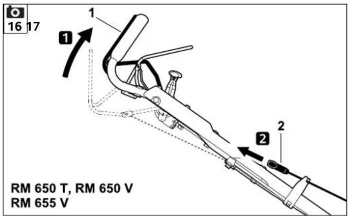
13.2 Starting the engine (RM 650 T, RM 650 V, RM 655 V)


Avoid damage to the machine! Do not start the engine in tall grass. Select a higher cutting height setting if the engine is difficult to start.

Thanks to the fixed throttle setting, the engine always operates at the optimum working speed after starting.
- Check the oil and fuel levels. ( 8.6)
Press motorstop lever (1) to the handlebar and hold.
Slowly pull out recoil starter rope (2) to the point of compression resistance. Then pull vigorously and quickly to arm's length. Slowly return recoil starter rope (2) again so that it is rolled up again. - Repeat the procedure until the engine starts.
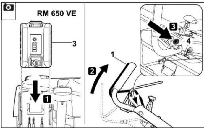
13.3 Starting the engine (RM 650 VE)

Avoid damage to the machine! Do not start the engine in tall grass. Select a higher cutting height setting if the engine is difficult to start.
Thanks to the fixed throttle setting, the engine always operates at the optimum working speed after starting.
- Check the oil and fuel levels. ( 8.6)
- Checking the battery: Check the charge state of the battery and recharge if necessary. (⇒ 9.5)
Insert battery (3).
- Press motorstop lever (1) to the handlebar and hold.
- Press start button (4) for max. 3 to 5 seconds and then release again. If the engine does not start, wait for 10 seconds before trying again. Avoid repeat starting when the engine is running.
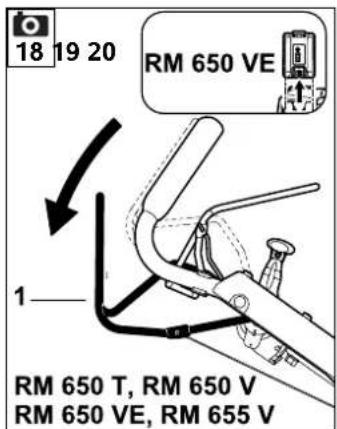
13.4 Stopping the engine (RM 650 T, RM 650 V, RM 650 VE, RM 655 V)

- To stop the engine, release motorstop lever (1).
Engine and mowing blade come to a stop after a short run-down time. - RM 650 VE: If the machine is unsupervised, remove the battery and store it separately from the machine as well as protected from unauthorised use (e.g. by children).
13.5 Starting the engine (RM 650 VS, RM 655 RS, RM 655 VS, RM 655 YS)
- Check the oil and fuel levels. (⇒ 8.6)
- RM 650 VS, RM 655 RS, RM 655 VS;
1 Set throttle lever (1) to the I position.
RM 655 YS:
When the engine is cold, set throttle lever (1) to the Choke position.
When the engine is warm or during hot weather, set throttle lever (1) to the I position.
- 2 Slowly pull recoil starter rope (2) to the point of compression resistance and then pull vigorously to arm's length. Slowly release the cable so that it can gradually be rolled up by the starter.
- Repeat the starting procedure until the engine starts.
RM 655 YS:
Set throttle lever (1) to the I position.


13.6 Engaging the mowing blade (RM 650 VS, RM 655 RS, RM 655 VS, RM 655 YS)

Avoid damage to the machine! Do not engage the mowing blade in tall grass and only engage it at the maximum engine speed.
Always engage it quickly in order to prevent unnecessary wear to the blade clutch.
- Pull blade stop lever (1) to the handlebar and hold. This releases blade clutch lever (2).
To engage the mowing blade, pull blade clutch lever (2) quickly straight back towards the handlebar as far as it will go. There, the lever is locked in the engaged position and can be released.
13.7 Disengaging the mowing blade (RM 650 VS, RM 655 RS, RM 655 VS, RM 655 YS)

- To disengage the mowing blade, release blade stop lever (1). Blade clutch lever (2) is released and returns automatically to its initial position. The mowing blade is disengaged and braked, the engine continues to run.
13.8 Stopping the engine (RM 650 VS, RM 655 RS, RM 655 VS, RM 655 YS)

Always disengage the mowing blade before stopping the engine. (13.7)
- To stop the engine, move the throttle lever (1) to the 0 position.

13.9 Self-propulsion
The lawn mower is equipped with rear-wheel drive.

RM 650 T:
Brisk forward speed
3,5 km/h
RM 655 RS:
Brisk forward speed
4,2 km/h
RM 650 V, RM 650 VE, RM 650 VS, RM 655 V, RM 655 VS, RM 655 YS: Continuously variable forward drive speed when using the driving speed lever
RM 650 V, RM 650 VE, RM 650 VS, RM 655 V, RM 655 VS: 2,6 km/h -4,6 km/h
RM 655 YS: 0,5 km/h - 6,3 km/h
Switching on self-propulsion:
- Start the engine. ( 13.2) , ( 13.5)
Pull self-propulsion lever (1) to the handlebar and hold. Self-propulsion is switched on and the lawn mower moves forward.
Avoid damage to the machine! Always actuate the self-propulsion lever fully (to the stop) in order to prevent resultant damage to the gearbox.
Setting the drive speed:
RM 650 V, RM 650 VE, RM 650 VS, RM 655 V, RM 655 VS: Avoid damage to the Vario gearbox! Only actuate driving speed lever (2) when the engine is running.
- Increasing the driving speed: Press driving speed lever (2) forwards when driving.
- Reducing the driving speed: Pull driving speed lever (2) rearwards when driving.


Switching off self-propulsion:
- Release self-propulsion lever (1). Self-propulsion is switched off and the lawn mower comes to a standstill. The engine continues to run.
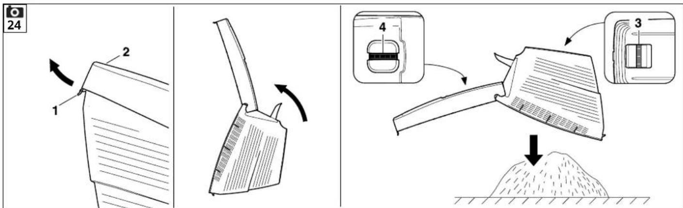
13.10 Emptying the grass catcher box

Risk of injury! Before detaching the grass catcher box, stop the engine or disengage the mowing blade and allow to come to a standstill.
A completely filled grass catcher box can weigh up to 20kg
- Detach the grass catcher box. ( 9.7)
- Open the grass catcher box at tab (1). Fold up the upper part of grass catcher box (2) and hold. Fold the grass catcher box rearwards and empty the clippings. The grass catcher box can be held securely and emptied easily using handles (3, 4) on the upper and lower part of the grass catcher box.
- Close the grass catcher box.
- Attach the grass catcher box. ( 9.7)
14. Maintenance
14.1 General
Risk of injury! Observe the safety instructions in the section "For your safety" ( 5)
Annual service by the specialist dealer:
The lawn mower should be inspected once annually by a specialist dealer. STIHL recommends STIHL specialist dealers.
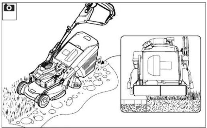
14.2 Cleaning the machine
Maintenance interval: After each use

Care of the machine will protect it against damage and extend its service life.

Risk of injury!
Stop the engine, detach the spark plug socket, remove the battery (on RM 650 VE) and allow the machine to cool.
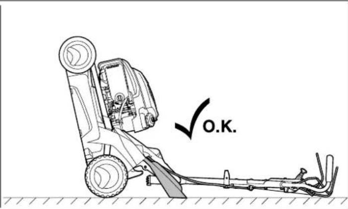
Empty the fuel tank (run empty) before placing the machine in the cleaning position.
The machine is only safely in the cleaning position when the discharge flap is open.
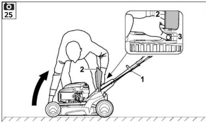
Cleaning position:
- RM650T, RM650V, RM650VRM 655 RS, RM 655 V, RM 655 VS, RM 655 YS: Detach the recoil starter rope from the rope guide. ( 8.3)
If necessary, remove the mulch insert ( 8.5) or detach the grass catcher box. ( 9.7) - Stand to the right of the machine to tilt it upwards.
- Set the upper handlebar to the lowest position (as far as the stop, the detent lever does not engage in this position). ( 9.3)
-
Open discharge flap (2) with your right hand and hold it open.
-
Hold the console with your left hand as shown and hold the discharge flap open. At the same time, press detent lever (3) with your thumb and hold.
- Hold the machine with your right hand by the front carrying handle and tilt it slowly backward until the handlebar touches the ground as shown.
- Release discharge flap (2) and detent lever (3) and check that the machine is standing securely.
Notes on cleaning:
- Clean off dirt using little water, with a brush or with a cloth. Never spray water onto engine components, seals or bearing points. If necessary, use a special cleaner (e.g. STIHL special cleaner).
- First, remove accumulated clipping deposits using a stick.
Always clean the mowing blade - under no circumstances should you hit the mowing blade (e.g. with a hammer) to loosen dirt.
Clean the engine cooling ribs. - Clean the grass catcher box and mulch insert using running water and a brush well away from the machine.
14.3 Checking blade wear
Maintenance interval:
Before each use
Risk of injury!
Blades are subjected to differing degrees of wear depending on the location and duration of use. If you use the machine on sandy ground or use it frequently under dry conditions, the blade will be subjected to greater loads and will wear more quickly than the average. A worn blade may break off and cause serious injuries. The instructions for blade maintenance must therefore always be observed.
- Tilt the mower upwards into the cleaning position. (⇒ 14.2)
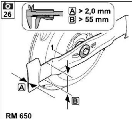
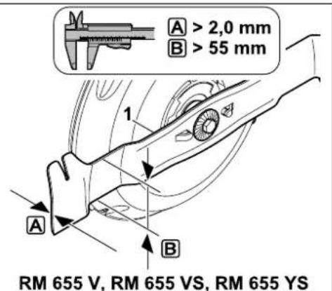
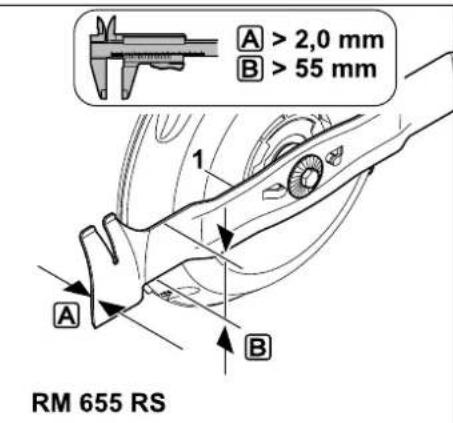
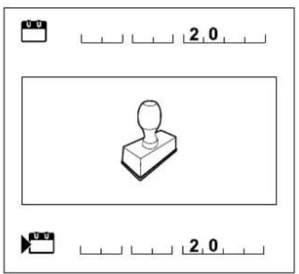
Clean mowing blade (1). - Use a slide calliper to measure blade thickness at 5 points at least. In particular, minimum thickness must also be ensured in the area of the blade wings.
- Check the minimum width at the narrowest point behind the blade wings using a slide calliper.
Blade thickness A: >2,0 mm
Minimum width B: > 55 mm
The blade must be replaced,
-
if it is damaged (notches, cracks),
-
if the measured values are achieved at one or more points or are outside the permissible limits.
If an accessory blade is installed on the lawn mower, different wear limits apply (see accessory instruction manual).

14.4 Removing and installing the blade

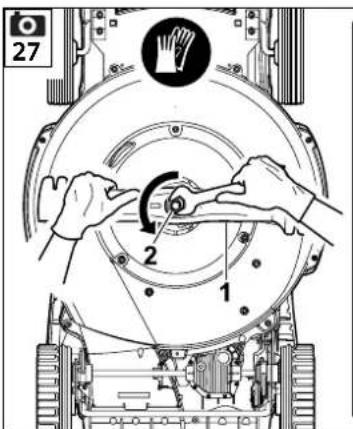
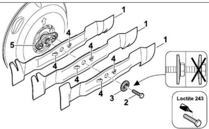
Removing the blade:
- Tilt the mower upwards into the cleaning position. (⇒ 14.2)
- Hold blade (1) and unscrew blade fastening screw (2).
- Remove blade (1), blade fastening screw (2) and retaining washer (3).
Installing the blade:

Risk of injury!
The blade (1) must only be installed as shown. The tabs (4) must face downwards and the curved wings must point upwards.
Observe the specified tightening torque for the blade fastening screw, as the secure attachment of the cutting tool depends on this. Additionally secure blade fastening screw (2) with Loctite 243.
Replace spring washer (3) each time the blade is installed and blade fastening screw (2) each time the blade is replaced.
- Clean the blade contact surface and blade bushing or blade holder.
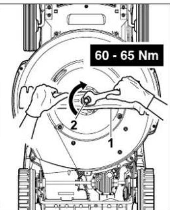
- Position blade (1) on the blade bushing or blade holder (5) with the curved wings pointing upwards (towards the machine).
- Fit a new retaining washer (3) as shown, screw in and tighten blade fastening screw (2). Tightening torque: 60 - 65 Nm
14.5 Sharpening the mowing blade
STIHL recommends having the mowing blade sharpened by a technician. Operation of the machine is impaired in the case of an incorrectly sharpened blade (incorrect sharpening angle, imbalance, etc.).
Sharpening instructions:
- Remove the mowing blade. ( 14.4)
Cool the mowing blade when sharpening, e.g. with water. The blade must not be allowed to display blue colouring, as this would reduce its cutting quality. - Sharpen the blade evenly to prevent vibrations due to imbalance.
- Observe the sharpening angle of 30^ .
After sharpening, remove any sharpening burr at the cutting edge using fine sandpaper if necessary. - Observe the wear limits. ( 14.3)
14.6 Engine
Maintenance interval:
See engine instruction manual.
General information:
Observe the operating and maintenance instructions contained in the attached engine instruction manual.
To achieve a long service life, it is always particularly important to maintain a sufficient level of oil and to change the oil and air filter regularly.
The recommended oil change intervals as well as information on engine oil and oil capacities can also be found in the engine instruction manual.
The cooling ribs must always be kept clean to ensure that the engine is adequately cooled.
14.7 Battery and charger maintenance
Maintenance interval:
See engine instruction manual.
14.8 Wheels and gearbox
The wheel bearings are maintenance-free.
The gearbox is maintenance-free.
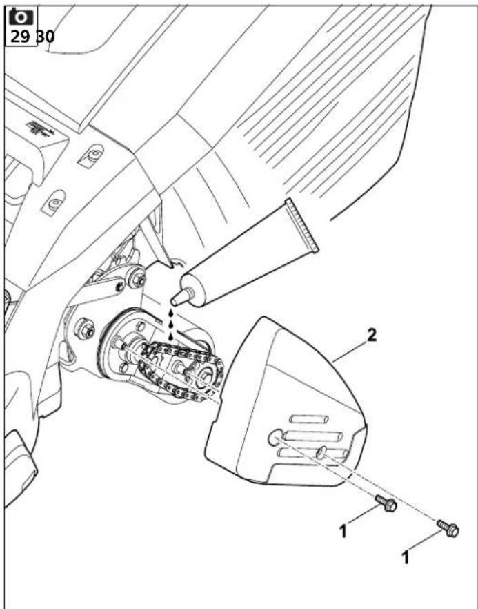
14.9 Lawn roller maintenance
The drive chain must be regularly lubricated, the ball bearings and rollers are maintenance-free.
Maintenance interval: Once annually or as required
- For servicing purposes, remove screw (1, Torx 25) and remove cover (2).
- Lubricate the drive chain using a commercially available grease.
14.10 Blade brake clutch (RM 650 VS, RM 655RS, RM 655VS, RM 655
Maintenance interval: Once a year
The blade brake clutch (BBC) is subject to natural wear. It may only be maintained by trained personnel. STIHL recommends STIHL specialist dealers.
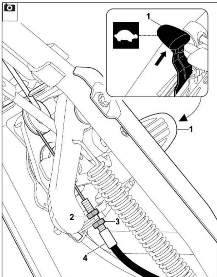
14.11 Adjusting the selfpropulsion cable (RM 655 YS)

Maintenance interval: Prior to initial use or as required
Adjustment of the cable is necessary
before the machine is operated for the first time
- if the maximum speed is not achieved
- if self-propulsion is permanently engaged. This means that the lawn mower automatically begins to move when the recoil starter rope is pulled, despite the self-propulsion lever not being actuated.
Adjusting the cable
Pull driving speed lever (1) all the way back.
- Loosen nuts (2, 3) to release the tension on cable (4).
- Start the engine. (⇒ 13.5)
Pull the self-propulsion lever to the handlebar and hold. ( 13.9)
Tension cable (4) using nut (3) until self-propulsion is activated. Then release the self-propulsion lever, stop the engine and tighten nut (2).

Check:
When the self-propulsion lever is not actuated, the cable is tensioned slightly and the machine can be pulled backwards - the wheels are not blocked.
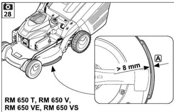
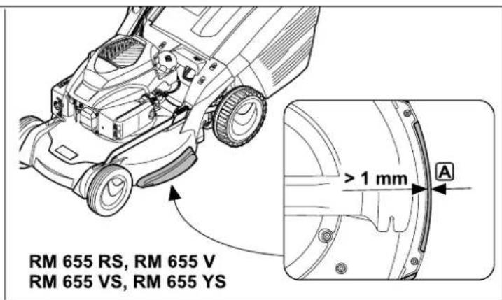
14.12 Checking skirting protector wear

Maintenance interval: Once a year
- Tilt the lawn mower upwards into the cleaning position. ( 14.2)
Measure the thickness of the left and right skirting protector.
RM650T,RM650V,RM650VE,RM650VS:
A>8mm
The housing must be replaced by a specialist dealer if the thickness is less than the specification at any point. STIHL recommends STIHL specialist dealers.
RM 655 RS, RM 655 V, RM 655 VS, RM 655 YS:
A>1 mm
The skirting protectors must be replaced if they are worn down to the limit value on the underside of the machine or if they no longer fully cover the housing.
14.13 Storage and periods of inoperation (winter break)
Store the machine in a dry, locked, dust-free place. Make sure that it is out of the reach of children.
Any faults must be remedied prior to storage. The machine must always be in a safe operating condition.
Empty the fuel tank and carburettor prior to storage (e.g. by running empty).
Also note the following points when storing the machine for long periods (winter break):
- Clean all external parts of the machine with care.
- Thoroughly lubricate/grease all moving parts.
- Unscrew the spark plug (see engine instruction manual) and pour approx. 3cm^3 of engine oil into the engine via the spark plug hole. Turn the engine several times with the spark plug removed (pull the recoil starter rope).
Fire hazard!
Keep the spark plug socket away from the spark plug hole due to the danger of ignition.
- Screw the spark plug back in (see engine instruction manual).
- Perform an oil change (see engine instruction manual).
RM 650 VE:
- Remove the battery and store separately from the machine out of reach of unauthorised persons in a dry, dust-free and frost-free room.
- Charge the battery completely before the start of the season. (⇒ 9.5)
15. Transport
15.1 Transport


Risk of injury!
Observe the section "For your safety" before transporting. ( 5.)
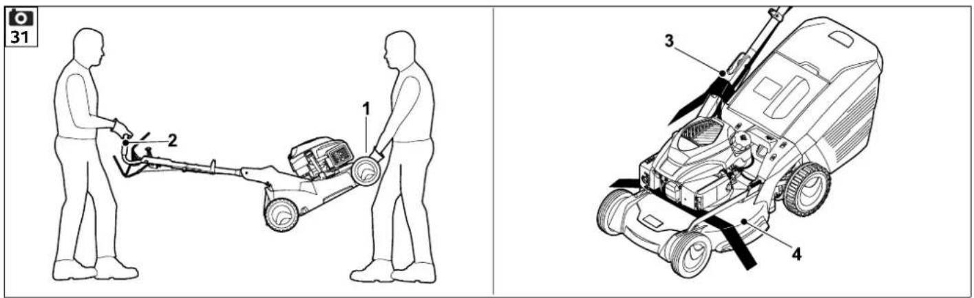
Always wear suitable safety clothing when transporting (safety shoes, thick gloves). Always detach the spark plug socket before lifting or transporting For safety reasons, STIHL recommends lifting or carrying the machine only with the aid of a second person. Before lifting, note the weight indicated in the section "Technical specifications".
Carrying the machine:
- Only hold the machine at carrying handle (1) and at handlebar (2). Always ensure sufficient distance between the mowing blade and your body, particularly your feet and legs.
Securing the machine (lashing):
- Secure the machine on the load floor using suitable fastening material and transport upright on its 4 wheels only.
- Fasten ropes or straps to handlebar console (3) and to housing (4).
16. Environmental protection
Lawn clippings should be composted and not disposed of in household waste.
The machine, its packaging and accessories are all produced from recyclable materials and must be disposed of accordingly.
By disposing of materials separately and in an environmentally friendly manner, recyclable waste can be re-used. For this reason, the machine should be disposed of for recycling at the end of its useful life. Pay particular attention to the information in the section "Disposal" during disposal. ( 5.10)
Consult your recycling centre or your specialist dealer for information on the proper disposal of waste products.

Li-lon
Waste products such as batteries must always be disposed of properly. Observe local regulations. Do not dispose of the battery with
domestic waste, but hand it in to a specialist dealer or at a hazardous waste collection point.
- Remove the battery ( 9.5) and dispose of separately from the lawn mower.
17. Minimising wear and preventing damage
Important information on maintenance and care of the product group petrol lawn mowers (STIHL RM)
STIHL assumes no liability for material or personal damage caused by the non-observance of information contained in the operating instructions, in particular with regard to safety, operation and maintenance, or which arise through the use of unauthorised attachment or spare parts.
Please always observe the following important information for the prevention of damage or excessive wear to your STIHL machine:
1. Wearing parts
Some parts of the STIHL machine are subject to normal wear even when used properly and must be replaced in due time depending on type and duration of use.
These include:
-
Mowing blades
-
Grass catcher box
-V-belt
-
Drive chain (RM 655 RS)
-
Skirting protectors (RM 655 RS, RM 655V, RM 655VS, RM 655Y
Battery (RM 650 VE)
2. Compliance with the information in this instruction manual
The STIHL machine must be used, maintained and stored with the care described in this instruction manual. Any damage caused by non-compliance with
the safety, operating and maintenance instructions is the sole responsibility of the user.
This applies in particular to:
- Product modifications not approved by STIHL.
- Use of fuel and lubricants not approved by STIHL (lubricants, petrol and engine oil, see engine manufacturer's specifications).
- The use of tools or accessories which are not approved or suitable for the machine, or are of inferior quality.
- Improper use of the product.
- Use of the product for sporting or competitive events.
- Resultant damage due to continued use of the product with defective components.
3. Maintenance operations
All operations listed in the section "Maintenance" must be performed regularly.
If these maintenance operations cannot be carried out by the user, a specialist dealer must be commissioned to perform them.
STIHL recommends that you have maintenance operations and repairs performed exclusively by a STIHL specialist dealer.
STIHL specialist dealers regularly attend training courses and are provided with technical information.
If these operations are neglected, faults may arise which are the responsibility of the user.
These include:
Corrosive and other resultant damage caused by incorrect storage.
- Damage to the machine through the use of inferior-quality spare parts.
- Damage due to untimely or inadequate maintenance or damage due to maintenance or repair work not performed in the workshops of specialist dealers.
18. Standard spare parts
Mowing blade for RM 650 T, RM 650 V, RM 650 VE, RM 650 VS: 6364 702 0100
Mowing blade for RM 655 V, RM 655 V S, manufacturer's brand: STIHL
RM 655 YS: - type: RM 650.0 T, RM 650.0 V
6374 702 0100 650.1 VE, RM 650.0 VS, RM
Mowing blade for RM 655 RS: 6374 702 0110
Blade fastening screw for RM 650 T, RM 650 V, RM 650 VE, RM 655 V: 9008 319 9075
Blade fastening screw for RM 650 VS, RM 655 RS, RM 655 VS, RM 655 YS: 9008 348 2440
Retaining washer: 0000 702 6600
The blade fastening screw and retaining washer must be renewed when replacing or installing the blade. Spare parts are available from a STIHL specialist dealer.
19. Declaration of conformity
19.1 EU declaration of conformity - STIHL RM 650.0 T/ V/ VS, RM 650.1 VE, RM 655.0 V/YS, RM 655.1 RS/ VS lawn mower
declares under our sole responsibility that- design : lawn mow
S, manufacturer's brand: STIHL
- type: RM 650.0 T, RM 650.0 V, RM 650.1 VE, RM 650.0 VS, RM 655.1 RS, RM 655.0 V, RM 655.1 VS, RM 655.0 YS
-cutting width, RM 650.0 T, RM 650.0 V, RM 650.1 VE, RM 650.0 VS: 48 cm
- cutting width, RM 655.1 RS, RM 655.0 V, RM 655.1 VS, RM 655.0 YS: 53 cm
- serial number:
RM 650.0 T, RM 650.0 V, RM 650.1
VE, RM 650.0 VS: 6364
RM 655.1 RS, RM 655.0 V, RM 655.1
VS, RM 655.0 YS: 6374
complies with the relevant provisions of Directives 2000/14/EC, 2006/42/EC, 2014/30/EU and 2011/65/EU and has been developed and manufactured in accordance with the versions of the following standards valid on the date of manufacture: EN ISO 5395-1, EN ISO 5395-2 and EN 14982.
Approved body involved:
TÜV Rheinland LGA Products GmbH
Tillystrasse 2, 90431 Nuremberg, Germany
The measured and guaranteed sound power levels were determined in accordance with Directive 2000/14/EC, Appendix VIII.
RM 650.0 T, RM 650.0 V, RM 650.0 VS
- Measured sound power level: 95.3 dB(A)
Guaranteed sound power level: 96 dB(A)
RM 650.1 VE
- Measured sound power level: 95,3 dB(A)
Guaranteed sound power level: 96 dB(A)
RM 655.0 V
- Measured sound power level: 97,5 dB(A)
Guaranteed sound power level: 98 dB(A)
RM 655.1 RS, RM 655.1 VS
- Measured sound power level: 97,2 dB(A)
Guaranteed sound power level: 98 dB(A)
RM 655.0 YS
- Measured sound power level: 97,4 dB(A)
Guaranteed sound power level: 98 dB(A)
The technical documents are stored at STIHL Tirol GmbH.
The year of manufacture and machine number are indicated on the lawn mower. Langkampfen, 02.06.2021
STIHL Tirol GmbH
p.p.

Matthias Fleischer, Head of Research and Development Division
p.p.

Sven Zimmermann, Head of Quality Department
19.2 UKCA-Declaration of Conformity STIHL RM 650.0 T, RM 650.0 V, RM 655.0 V, RM 655.1 RS, RM 655.1 VS Lawn Mower
STIHL Tirol GmbH
Hans Peter Stihl-Strasse 5
6336 Langkampfen
Austria
declares under our sole responsibility that
design: lawn mower
- manufacturer's brand: STIHL
type: RM 650.0 T, RM 650.0 V, RM 655.0 V, RM 655.1 RS, RM 655.1 VS
-cutting width: RM 650.0 T, RM 650.0 V: 48 cm
-cutting width:RM 655.1 RS, RM 655.0 V,RM 655.1 VS:53 cm
- serial number:
RM 650.0 T, RM 650.0 V: 6364
RM 655.1 RS, RM 650.0 V, RM 655.1 VS: 6374
complies with the relevant provisions of UK Regulations Noise Emission in the Environment by Equipment for use Outdoors Regulations 2001, Supply of Machinery (Safety) Regulations 2008, Electromagnetic Compatibility Regulations 2016 and The Restriction of the Use of Certain Hazardous Substances in Electrical and Electronic Equipment Regulations 2012 and has been developed and manufactured in accordance with the versions of the following standards valid on the date of manufacture: EN ISO 5395-1, EN ISO 5395-2 and EN ISO 14982.
The measured and guaranteed sound power levels were determined in accordance with the Noise Emission in the Environment by Equipment for use Outdoors Regulations 2001, Schedule 11.
Approved Body involved: TUV Rheinland UK LTD 1011 Stratford Road Solihull, B90 4BN
RM 650.0 T, RM 650.0 V
- Measured sound power level: 95.3 dB(A)
Guaranteed sound power level: 96 dB(A)
RM 655.0 V
- Measured sound power level: 97.5 dB(A)
Guaranteed sound power level: 98 dB(A)
RM 655.1 RS, RM 655.1 VS
- Measured sound power level: 97.2 dB(A)
Guaranteed sound power level: 98 dB(A)
The technical documents are stored at STIHL Tirol GmbH.
The year of manufacture and machine number are indicated on the lawn mower.
Langkampfen, 02.11.2021
STIHL Tirol GmbH
p.p.

Matthias Fleischer, Vice President Product Development
p.p.

Sven Zimmermann, Director Quality Management
20. Technical specifications
RM 650.0 T, RM 650.0 V, RM 650 VE, RM 650.0 VS:
Serial number 6364
Cutting width 48 cm
Cutting tool Cutter bars
Cutter bar speed 2800 rpm
Cutting height 25 - 85 mm
Tightening torque for
blade fastening
screw 60 - 65 Nm
Wheel diameter
(front) 200mm
Wheel diameter
(rear) 230~mm
Grass catcher box
capacity 70 I
Length 167 cm
Width 52 cm
Height 112 cm
Engine
Design 4-stroke com
Nominal output at 2,6 - 2800
nominal speed kW - rpm
RM 650.0 T:
Engine type Kohler HD775
designation
Displacement 173 ccm
Starter Rope start
Cutter bar drive Permanent
Self-propulsion, rear Single-speed
wheels gearbox
Weight 45 kg
Fuel tank 1,4 I
Sound emissions
Measurement in accordance with 2000/14/EC/S.I. 2001/1701:
Guaranteed sound
power level L_WAd 96 dB(A)
Measurement in accordance with EN ISO
5395-2:
Sound pressure level
at workplace L_pA 81 dB(A)
Uncertainty K_pA 2 dB(A)
Hand-arm vibrations
Specified vibration characteristic in
accordance with EN 12096:
Measured value a_hw 3,80 m/sec2
Uncertainty Khw 1,90 m/sec2
Measurement in accordance with EN ISO
5395-2. EN 20643
RM 650.0 V:
Engine type Kohler HD775
designation
Displacement 173 ccm
Starter Rope start
Cutter bar drive Permanent
Self-propulsion, rear
wheels Vario gearbox
Weight 46 kg
Fuel tank 1,4 I
Sound emissions
Measurement in accordance with
2000/14/EC/S.l. 2001/1701:
Guaranteed sound
power level L_WAd 96 dB(A)
Uncertainty KwA 1,1 dB(A)
Measurement in accordance with EN ISO
5395-2:
Sound pressure level
at workplace L_pA 81 dB(A)
Uncertainty K_pA 2 dB(A)
Hand-arm vibrations
Specified vibration characteristic in
accordance with EN 12096:
Measured value a_hw 3,80 m/sec2
Uncertainty Khw 1,90 m/sec2
Measurement in accordance with EN ISO
5395-2, EN 20643
RM 650.1 VE:
Engine type EVC 300 E
designation
Displacement 166 cm
Lithium-ion battery
and charger instruction
manual
Starter Electric start
Cutter bar drive Permanent
Self-propulsion, rear
wheels Vario gearbox
Weight 44 kg
Fuel tank 0,91
Sound emissions
Measurement in accordance with
2000/14/EC/S.I. 2001/1701:
Guaranteed sound
power level L_WAd 96 dB(A)
Measurement in accordance with EN ISO
5395-2:
Sound pressure level
at workplace L_pA 82 dB(A)
Uncertainty K_DA 2 dB(A)
Hand-arm vibrations
Specified vibration characteristic in
accordance with EN 12096:
Measured value a_hw 3,00 m/sec²
Uncertainty K_hw
Measurement in accordance with EN ISO
5395-2, EN 20643
RM 650.0 VS:
Engine type Kohler HD775
designation
Displacement 173 ccm
Starter Rope start
Cutter bar drive BBC
Self-propulsion, rear
wheels Vario gearbox
Weight 50 kg
Fuel tank 1,4
Sound emissions
Measurement in accordance with 2000/14/EC/S.l. 2001/1701:
Guaranteed sound
power level L_WAd 96 dB(A)
Measurement in accordance with EN ISO 5395-2:
Sound pressure level
at workplace L_pA 81 dB(A)
Uncertainty K_pA 2 dB(A)
Hand-arm vibrations
Specified vibration characteristic in accordance with EN 12096:
Measured value a_hw 3,80 m/sec2
Measurement in accordance with EN ISO 5395-2, EN 20643
RM 655.1 RS, RM 655.0 V, RM 655.1 VS, RM 655.0 YS:
Serial number 6374
Cutting width 53 cm
Cutting tool Cutter bars
Cutter bar speed 2800 rpm
Cutting height 25 - 85 mm
Cutting height
(RM 655.1 RS) 20 - 80 mm
Tightening torque for blade fastening
screw 60-65Nm
Wheel diameter
(front) 200 mm
Roller diameter (rear) 90 mm
Grass catcher box
capacity 701
Length 171 cm
Width 59cm
Height 112 cm
RM 655.1 RS:
Cutter bar drive BBC
Roller drive Single-speed gearbox
Weight 56 kg
Engine
Design 4-stroke com
bustion engine
Manufacturer, type Kohler HD775
Displacement 173 ccm
Starter Rope start
Nominal output at 2,6 - 2800
nominal speed kW - rpm
Fuel tank 1,4 I
Sound emissions
Measurement in accordance with 2000/14/EC / S.l. 2001/1701:
Guaranteed sound
power level L_WAd 98 dB(A)
Measurement in accordance with EN ISO 5395-2:
Sound pressure level
at workplace L_pA 84 dB(A)
Uncertainty K_D 2 dB(A)
Hand-arm vibrations
Specified vibration characteristic in accordance with EN 12096:
Measured value a_hw 2,80 m/sec²
Uncertainty Khw 1,40 m/sec2
Measurement in accordance with EN ISO 5395-2, EN 20643
RM 655.0 V:
Cutter bar drive Permanent
Self-propulsion, rear
wheels Vario gearbox
Weight 46 kg
Engine
Design 4-stroke combustion engine
Manufacturer, type Kohler HD775
Displacement 173 ccm
Starter Rope start
Nominal output at 2,6 - 2800
nominal speed kW - rpm
Fuel tank 1,4 I
Sound emissions
Measurement in accordance with
2000/14/EC / S.I. 2001/1701:
Guaranteed sound
power level L_WAd 98 dB(A)
Measurement in accordance with EN ISO 5395-2:
Sound pressure level
at workplace L_pA 84 dB(A)
Uncertainty K_D 2 dB(A)
Hand-arm vibrations
Specified vibration characteristic in accordance with EN 12096:
Measured value a_hw 3,80 m/sec2
Uncertainty Khw 1,90 m/sec2
Measurement in accordance with EN ISO
5395-2, EN 20643
RM 655.1 VS:
Cutter bar drive BBC
Self-propulsion, rear
wheels Vario gearbox
Weight 50 kg
Engine
Design 4-stroke combustion engine
Manufacturer, type Kohler HD775
Displacement 173 cm
Starter Rope start
Nominal output at 2,6 - 2800
nominal speed kW - rpm
Fuel tank 1,4 I
Sound emissions
Measurement in accordance with 2000/14/EC / S.l. 2001/1701:
Guaranteed sound
power level L_WAd 98 dB(A)
Uncertainty KwA xx dB(A)
Measurement in accordance with EN ISO 5395-2
Sound pressure level
at workplace L_pA 84 dB(A)
Uncertainty K_pA 2 dB(A)
Hand-arm vibrations
Specified vibration characteristic in accordance with EN 12096:
Measured value a_hw 3.80 m/sec2
Measurement in accordance with EN ISO 5395-2, EN 20643
RM 655.0 YS:
Cutter bar drive BBC
Self-propulsion, rear Hydrostatic wheels gearbox
Weight 56 kg
Engine
Design 4-stroke combustion engine
Manufacturer, type Kawasaki FJ 180 V KAI
Displacement 179 ccm
Starter Rope start
Nominal output at 2,9 - 2800
nominal speed kW - rpm
Fuel tank 1,6 I
Sound emissions
Measurement in accordance with
2000/14/EC / S.I. 2001/1701:
Guaranteed sound
power level L_WAd 98 dB(A)
Measurement in accordance with EN ISO 5395-2:
Sound pressure level
at workplace L_pA 84 dB(A)
Uncertainty K_pA 2 dB (A)
Hand-arm vibrations
Specified vibration characteristic in accordance with EN 12096:
Measured value a_hw 3,00 m/sec2
Uncertainty K_hw 1,50 m/sec²
Measurement in accordance with EN ISO 5395-2, EN 20643
Transporting lithium-ion batteries:
RM 650 VE: The battery is subject to the requirements for transporting hazardous goods. The battery is classed as a UN 3480 (lithium-ion battery) and has been tested in accordance with the UN Manual of Tests and Criteria, Part III, subsection 38.3.
The user may carry these batteries to the place of use of the machine without further restrictions during road transport.
Country-specific legislation must be observed in the case of air or sea transport.
For further transport instructions, see http://www.stihl.com/safety-data-sheets
20.1 REACH
REACH is an EC Directive for the registration, evaluation, authorisation and restriction of chemicals.
Information on compliance with the REACH Directive (EC) No. 1907/2006 is available from www.stihl.com/reach.
21. Troubleshooting
If necessary, contact a specialist dealer; STIHL recommends STIHL specialist dealers.
See engine instruction manual.
Fault:
Engine not starting
Possible cause:
- RM650T, RM650V, RM650VE, RM655V: Motorstop lever not pressed.
- RM650VS, RM655RS, RM655VS RM 655 YS: Throttle lever is in Stop position.
- RM 650 VE: Battery discharged or defective.
- No fuel in tank; fuel line blocked.
- Inferior, dirty or old fuel in tank.
Air filter dirty. - Spark plug socket detached from spark plug; ignition lead not properly fastened to socket.
-
Spark plug dirty or damaged; incorrect electrode gap.
Lawn mower housing blocked. -
RM 650 VS, RM 655 RS, RM 655 VS, RM 655 YS: Throttle cable disengaged or defective (e.g. kinked).
Remedy:
- RM650T, RM650V, RM655V: Press motorstop lever to handlebar and hold. (→ 10.2)
- RM 650 VS, RM 655 RS, RM 655 VS, RM 655 YS: Set throttle lever to Choke or Start position. ( 13.5)
- RM 650 VE: Charge or replace battery.
(⇒ 9.5)
-Top up fuel;clean fuel line.
Always use fresh, good quality fuel, unleaded petrol; clean carburettor. - Clean air filter.
- Connect spark plug socket; check connection between ignition lead and socket.
- Clean or replace spark plug; adjust electrode gap.
Clean lawn mower housing. First disconnect spark plug socket and, for model RM 650 VE, also remove battery. ( 9.5) - RM 650 VS, RM 655 RS, RM 655 VS, RM 655 YS: Attach or replace throttle cable.
Fault:
Starting problems or deteriorating engine power
Possible cause:
Lawn mower housing blocked.
- Mowing at an excessively low cutting height or fast speed
Water in fuel tank and carburettor; carburettor blocked
- Contaminated fuel tank
- Dirty air filter
- Dirty spark plug
Remedy:
Clean law mower housing. First disconnect spark plug socket and, for model RM 650 VE, also remove the battery. ( 9.5)
- Adapt cutting height and reduce mowing speed
- Empty fuel tank, clean fuel line and carburettor
Clean fuel tank
- Clean/replace air filter 0, x
Clean spark plug
Fault:
Engine overheating.
Possible cause:
- Oil level in engine too low.
Cooling ribs dirty.
Remedy:
- Change engine oil. (⇒ 8.6)
Clean cooling ribs. ( 14.2)
Fault:
No drive when self-propulsion lever is actuated.
Possible cause:
- RM 655 YS: Self-propulsion cable incorrectly adjusted.
- Self-propulsion cable defective (e.g. kinked).
V-belt worn.
Gearbox defective.
Remedy:
- RM 655 YS: Check cable adjustment.
(⇒ 14.11) - Replace cable.
-ReplaceV-belt.
-Replace gearbox.
Fault:
Speed control not functioning
Possible cause:
- Driving speed lever moved in wrong direction.
Cable disengaged or defective (e.g. kinked).
Remedy:
- Move driving speed lever in the correct direction. ( 13.9)
- Attach or replace cable.
Fault:
Mowing channel blocked
Possible cause:
- Mowing blade is worn.
- Mowing grass which is too long or too wet.
-RM650VS,RM655RS,RM655VS RM655YS:Engine speed is too low.
Remedy:
-Replace mowing blade. ( 14.4)
- Adapt cutting height and mowing speed to mowing conditions. ( 12.) ( 9.4)
-RM650VS,RM655RS,RM655VS RM655YS:Set the throttle lever to the Start position. ( 13.5)
Fault:
Poor cut, lawn turning yellow
Possible cause:
- Blade is blunt or worn.
- Mowing speed is too high in relation to cutting height.
- RM650VS, RM655RS, RM655QS RM 655 YS: Engine speed is too low.
Remedy:
-
Sharpen or replace blade ( 14.3) , ( 14.4)
-
Reduce mowing speed and/or select correct cutting height (do not work at lowest cutting height). ( 9.4) ( 13.9)
- RM 650 VS, RM 655 RS, RM 655 VS, RM 655 YS: Set throttle lever to Start position. (→ 13.5)
Fault: Excessive vibration during operation
Possible cause:
- Blade fastening screw loose.
- Blade imbalance due to incorrect sharpening or fracture.
- Cutting unit defective.
- Engine mounting loose.
Remedy:
-Tighten blade fastening screw. ( 14.4)
- Re-sharpen (balance) or replace blade.
(⇒ 14.5),
- Check blade, blade shaft and blade fastening and repair if necessary.
- Tighten engine mounting bolts.
22. Service schedule
22.1 Handover confirmation
Model:
Serial number:

Date:
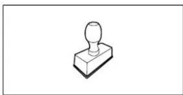
Next service Date:
22.2 Service confirmation
Please hand this instruction manual to your STIHL specialist dealer in the case of maintenance operations. He will confirm the service operations performed in the pre-printed boxes.
00 Service performed on
Next service date
Chere clientele, cher client,
(RM 650 VS, RM 655 RS)
RM 655 VS, RM 655 YS) 89
Entrainement 89
(RM 650 VS, RM 655 RS,
RM 655 VS, RM 655 YS) 92
RM 650 VS, RM 655 RS, RM 655 VS, RM 655 YS:
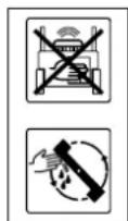
Attention - Risque de blessures!
RM650V, RM650VE, RM650VS, RM655V, RM655VS, RM655YS:

RM650T, RM650V, RM655V:
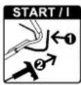
RM 650 VS, RM 655 RS, RM 655 VS, RM 655 YS:
RM 655 RS, RM 655 VS,
RM 655 RS, RM 655 V, RM 655 VS, RM 655 YS:
A>1 mm
2000/14/EC/S.I.2001/1701:
Niveau de puis
sanceacoustique
garanti LwAd
96 dB(A)
Incertitude KWA
1,1 dB(A)
2000/14/EC / S.I. 2001/1701:
Niveau de puis
sanceacoustique
garanti LwAd 96 dB(A)
Incertitude KwA 1,1 dB(A)
2000/14/EC/S.I.2001/1701:
Niveau de puis
sanceacoustique
garanti LwAd 96 dB(A)
RM 655.1 RS, RM 655.0 V, RM 655.1 VS, RM 655.0 YS :
N° de série 6374
2000/14/EC / S.I. 2001/1701:
Niveau de puis
sanceacoustique
2000/14/EC/S.I.2001/1701:
Niveau de puis
sanceacoustique
garanti LwAd
98 dB(A)
Incertitude KwA
0,9 dB(A)
2000/14/EC/S.I.2001/1701:
Niveau de puis
sanceacoustique
garanti LwAd
98 dB(A)
Incertitude KWA
xx dB(A)
RM 655 RS, RM 655 VS,
RM 655 YS)123
RM 650 VS, RM 655 RS, RM 655 VS, RM 655 YS:
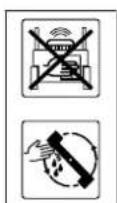
RM 650 VS, RM 655 RS, RM 655 VS, RM 655 YS:
(RM 650 VS, RM 655 RS, RM 655 VS, RM 655 YS)
(RM 650 VS, RM 655 RS, RM 655 VS, RM 655 YS)
(RM 650 VS, RM 655 RS, RM 655 VS, RM 655 YS)
6 Startknop
(RM 650 VE)
9.3 Duwstang instellen


Gevaar op klemmen!
RM 655 RS, RM 655 V, RM 655 VS, RM 655 YS:
A>1 mm
Meting conform 2000/14/EC / S.I.
2001/1701:
Meting conform EN ISO 5395-2:
Meting conform 2000/14/EC / S.I. 2001/1701:
Meting conform EN ISO 5395-2:
Geluidsdrukniveau op werkplek LpA 81 dB(A) Onzekerheid KDA 2 dB(A)
Vibrations hand-arm
Meting conform 2000/14/EC / S.l. 2001/1701:
Meting conform EN ISO 5395-2:
Meting conform 2000/14/EC / S.I. 2001/1701:
Gegarandeerd
geluidsniveauu LwAd 96 dB(A)
Meting conform EN ISO 5395-2:
Geluidsdrukniveaua
opwerkplek L_pA 81 dB(A)
Onzekerheid K_pA 2 dB(A)
Vibrations hand-arm
RM 655.1 RS, RM 655.0 V, RM 655.1 VS, RM 655.0 YS:
Serienummer 6374
Snijbvrede 53 cm
Meting conform 2000/14/EC / S.I.
2001/1701:
Gegarandeerd
geluidsniveau LwAd 98 dB(A)
Meting conform EN ISO 5395-2:
Geluidsdrukniveau
opwerkplek LpA 84 dB(A)
Onzekerheid K_pA 2 dB(A)
Vibrations hand-arm
Meting conform 2000/14/EC / S.l.
2001/1701:
Gegarandeerd
geluidsniveauu LwAd 98 dB(A)
Meting conform EN ISO 5395-2:
Geluidsdrukniveau
opwerkplek L_pA 84 dB(A)
Onzekerheid K_pA 2 dB(A)
Vibrations hand-arm
Meting conform 2000/14/EC / S.I. 2001/1701:
Gegarandeerd
geluidsniveauu LwAd 98 dB(A)
Meting conform 2000/14/EC / S.I. 2001/1701:
Gegarandeerd
geluidsniveauu LwAd 98 dB(A)
Meting conform EN ISO 5395-2:
Geluidsdrukniveau
opwerkplek L_pA 84dB(A)
Onzekerheid K_pA 2 dB (A)
Vibrations hand-arm
(RM 650 VS, RM 655 RS,
RM 655 VS, RM 655 YS) 151
RM 655 RS, RM 655 VS,
RM 655 YS)151
Trazione 151
RM 650 VS, RM 655 RS, RM 655 VS, RM 655 YS:
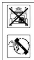
RM650T, RM650V, RM655V:
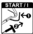
RM650V, RM650VE, RM650VS, -RM655V, RM655VS, RM655YS:


RM650T, RM650V, RM650VE, RM650VS, RM655V, RM655VS, RM655YS:
(RM 650 VS, RM 655 RS, RM 655 VS, RM 655 YS)
2 Staffa trazione
(RM 650 VS, RM 655 RS, RM 655 VS, RM 655 YS)
(RM 650 VS, RM 655 RS, RM 655 VS, RM 655 YS)
I modelli RM 650 VS, RM 655 RS,
Spessore lama A: >2,0 mm
RM 655 RS, RM 655 V, RM 655 VS, RM 655 YS:
A>1 mm
Misurazione conforme a 2000/14/EC / S.I. 2001/1701:
Livello di potenza
sonora garantito
LwAd 96 dB(A)
K_hw 1,90 m/sec2
RM 655.1 RS, RM 655.0 V, RM 655.1 VS, RM 655.0 YS:
Misurazione conforme a 2000/14/EC / S.I. 2001/1701:
Misurazione conforme a 2000/14/EC / S.I. 2001/1701:
Misurazione conforme a 2000/14/EC / S.I. 2001/1701:
Livello di potenza
sonora garantito
LwAd 98 dB(A)
Misurazione conforme a 2000/14/EC / S.I. 2001/1701:
Livello di potenza
sonora garantito
L_WAd 98 dB(A)
Embrague-freno de cucilla (BBC) 180
Embrague-freno de cucilla (RM 650 VS, RM 655 RS, RM 655 VS, RM 655 YS) 18
RM 650 VS, RM 655 RS, RM 655 VS, RM 655 YS:

RM650T, RM650V, RM655V:
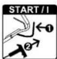
Arrancar el motor de combustion
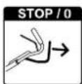
J Accumulator (RM 650 VE) 1
K Cargador (RM 650 VE) 1
RM 650 VS, RM 655 RS, RM 655 VS, RM 655 YS:
RM650T, RM650V, RM650VE, RM650VS, RM655V, RM655VS, RM655YS:
RM650V, RM650VE, RM653
13.6 Acoplar la cucilla (RM 650 VS, RM 655 RS, RM 655 VS, RM 655 YS)


13.7 Desacoplar la cucilla (RM 650 VS, RM 655 RS, RM 655 VS, RM 655 YS)

14.10 Embrague-freno de cucilla (RM 650 VS, RM 655 RS, RM 655 VS, RM 655 YS)
RM 655 RS, RM 655 V, RM 655 VS, RM 655 YS:
A>1 mm
RM 655.1 RS, RM 655.0 V, RM 655.1 VS, RM 655.0 YS:
(RM 650 VS, RM 655 RS)
RM 655 VS, RM 655 YS) 215
Mecanismo de transicao 215
RM 650 VS, RM 655 RS, RM 655 VS, RM 655 YS:
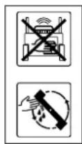
RM650T, RM650V, RM655V:
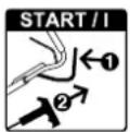
Ligar o motor de combustao
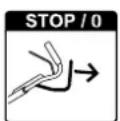
RM650V, RM650VE, RM650VS, -RM655V, RM655VS, RM655YS:

RM 650 VS, RM 655 RS, RM 655 VS, RM 655 YS:
RM650T, RM650V, RM650VE, RM650VS, RM655V, RM655VS, RM655YS:
O cortador de relva está equipado de série com um disposicao de mulching. No momento da entrega, este disposicao de mulching está montado no canal de expulsion.

RM 655 RS, RM 655 V, RM 655 VS, RM 655 YS:
A>1 mm
RM655V, RM655VS, RM655YS)
Bacteria (RM 650 VE)
Medicao conforme 2000/14/EC/S.I. 2001/1701:
Nível de potência
acústica garantido
LwAd 96 dB(A)
Medicao conforme 2000/14/EC/S.I. 2001/1701:
Nivel de potência
acústica garantido
Medicao conforme 2000/14/EC/S.I. 2001/1701:
Nivel de potência
acústica garantido
Medicão conforme 2000/14/EC/S.I.
2001/1701:
Nivel de potência
acústica garantido
LwAd 96 dB(A)
RM 655.1 RS, RM 655.0 V, RM 655.1 VS, RM 655.0 YS:
Medicao conforme 2000/14/EC/S.I. 2001/1701:
Nivel de potência
acústica garantido
L_WAd 98 dB(A)
Incerteza KwA xx dB(A)
Medicao conforme EN ISO 5395-2:
Nível de pressão
Medicao conforme 2000/14/EC/S.I. 2001/1701:
Nível de potência
acústica garantido
LwAd 98 dB(A)
Medicao conforme 2000/14/EC/S.I. 2001/1701:
Nível de potência
acústica garantido
Medicao conforme 2000/14/EC/S.I. 2001/1701:
Nivel de potencia
acústica garantido
LwAd 98 dB(A)
Incerteza KwA 1,0 dB(A)
Medicao conforme EN ISO 5395-2:
Nível de pressão
Knivclutch (RM 650 VS,
RM 655 RS, RM 655 VS,
RM 655 YS)247
Justere vaieren for fremdrift
(RM 655 YS) 247
Kontrollere slitasje pâ
skrapelistene 247
RM 650 VS, RM 655 RS, RM 655 VS, RM 655 YS:

Koble inn fremdriften

Gassregulating
Choke-posisjon (kun RM 655 YS) skyv gasshendelen forover til den stopper

RM650T, RM650V, RM655V:
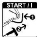
Starte forbrenningsmotoren
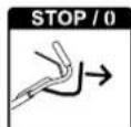
Slå av forbrenningsmotoren

RM 650 VS, RM 655 RS, RM 655 VS, RM 655 YS:
Plasser forst BBC-vaieren ( = 7mm) i foringen (4).
- Legg alle vairne (3) i vaierforingen (5).
- Fell opp styret til arbeidsposisjon.
(⇒ 9.3) - RM 655 YS: Justere vaieren for fremdrift. (⇒ 14.11)

14.10 Knivclutch (RM 650 VS, RM 655 RS, RM 655 VS, RM 655 YS)
RM 655 RS, RM 655 V, RM 655 VS, RM 655 YS:
A>1 mm
Skrapelistene skal skiftes nár de er slitt.

Knivskrue for RM 650 VS, RM 655 RS, RM 655 VS, RM 655 YS: 90083482440
Laseskive: 0000 702 6600

Knivskruen eller laseskiven skal skiftes nár kniven skiftes ell monteres. Reservedeler fores av STIHL forhandlere.
19. Produsentensamsvarserklaering
19.1 Produsentens EU-samsvarserklaering for gresskipper STIHL RM 650.0 T/ V/ VS, RM 650.1 VE, RM 655.0 V/YS, RM 655.1 RS/ VS
RM 655.1 RS, RM 655.0 V, RM 655.1 VS, RM 655.0 YS:
Serieidentifikasjon 6374
Klippebredde 53 cm
Klippeenhet Knivbjelke
Turtall, knivbjelke 2800 o/min
Klippehoyde 25 - 85 mm
Klippehoyde
(RM 655.1 RS) 20 - 80 mm
Tiltrekkingsmoment
knivskrue 60 - 65 Nm
Hjul- foran 200mm
Valse-0bak 90 mm
Fyllmengde i
oppsmler 701
Lengde 171 cm
Bredde 59 cm
Hoyde 112 cm
RM 655.1 RS:
Malt verdi ahw 2,80 m/sek2
Usikkerhet Khw 1,40 m/sek2
Måling i henhold til EN ISO 5395-2.
EN 20643
RM 655.0 V:
RM 655 RS, RM 655 VS,
RM 655 YS) 275
Stalla in drivningsens wire
(RM 655 YS) 275
Kontrollera skyddlisternas slitage 275
Varning - risk for olycksfall!
RM 650 VS, RM 655 RS, RM 655 VS, RM 655 YS:
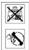
Varning - risk for personskador!
Knivtjocklek A: >2,0 mm
Minsta bredd B: > 55 mm
RM 655 RS, RM 655 V, RM 655 VS, RM 655 YS:
A>1 mm
Knivskruv for RM 650 VS, RM 655 RS, RM 655 VS, RM 655 YS: 90083482440
Låsbricka: 0000 702 6600

RM 655.1 RS, RM 655.0 V, RM 655.1 VS, RM 655.0 YS:
Modellnummer 6374
Klippbredd 53 cm
Klippaggregat knivbalk
Varvatal knivbalk 2800 varv/min
Klipphofd 25 - 85 mm
Klipphöjd
(RM 655.1 RS) 20 - 80mm
Atdragningsmoment
knivskruv 60-65Nm
Hjul-Øfram 200 mm
Vals-0bak 90 mm
Fyllvolym
grasuppsamlare 701
Längd 171 cm
Bredd 59 cm
Höjd 112 cm
RM 655.1 RS:
Driving knivbalk BBC
1-vaxlad
vaxellada
Vikt 56 kg
Forbränningsmotor
Typ 4-takts
forbränningsmo
RM 650 VS, RM 655 RS, RM 655 VS, RM 655 YS:

RM650T, RM650V, RM650VE, RM650VS, RM655V, RM655VS, RM655YS:
RM 655 RS, RM 655 V, RM 655 VS, RM 655 YS:
A>1 mm
Suojalistat on vaihdettava, kun rungon
Mittaus standardien 2000/14/EC / S.I.
2001/1701 mukaan:
Taattu aenenteho
Mittaus standardien 2000/14/EC / S.I.
2001/1701 mukaan:
Taattuaaenenteho
RM 655.1 RS, RM 655.0 V, RM 655.1 VS, RM 655.0 YS:
Sarjatunnus: 6374
Leikkuuleveys 53 cm
Mittaus standardien 2000/14/EC / S.I.
2001/1701 mukaan:
Taattu aenenteho
taso LwAd 98 dB(A)
Epavarmuus KwA: xx dB(A)
Mittaus standardin EN ISO 5395-2 mukaan:
Aaenpainetasoyo
RM 655 RS, RM 655 VS,
RM 655 YS) 330
5.5 Transport of maskinen
Risiko for at snuble!
RM 650 VS, RM 655 RS, RM 655 VS, RM 655 YS:
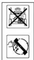
OBS - risiko for kvaestelser!
RM650T, RM650V, RM655V:
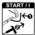
RM650VS,RM655RS,RM65V9 RM655YS:
Placer BBC-kabeltraekket ( = 7mm) som det forste i foringen (4).
RM650T, RM650V, RM650VE, RM650VS, RM655V, RM655VS, RM655YS:
- RM650T, RM650V, RM650VS, RM655RS, RM655V, RM655VS, RM655YS:
RM 655 RS, RM 655 V, RM 655 VS, RM 655 YS:
A>1 mm
Måling iht. 2000/14/EC / S.I. 2001/1701:
Garanteret lydeffekt
niveau L_WAd 96 dB(A)
Usikkerhed K_WA 1,1 dB(A)
Måling iht. EN ISO 5395-2:
Stojniveau pa
arbejdspladen L_pA 81 dB(A)
Usikkerhed K_pA 2dB(A)
Hand-arm vibrationer
Anfort vibrationskarakteristik ith.
EN 12096:
Malt vardi ahw 3,80 m/sek2
Måling iht. 2000/14/EC / S.I. 2001/1701:
Garanteret lydefeffekt
Måling iht. 2000/14/EC / S.I. 2001/1701:
Garanteret lydeffekt
Måling iht. 2000/14/EC / S.I. 2001/1701:
Garanteret lydeffekt
niveau L_WAd 98 dB(A)
Usikkerhed KwA xx dB(A)
Måling iht. EN ISO 5395-2:
Stojniveau pa
arbejdspladsen L_pA 84 dB(A)
Usikkerhed K_pA 2 dB(A)
Hand-arm vibrationer
Anfort vibrationskarakteristik iht.
EN 12096:
Malt vardi ahw 2,80 m/sek2
Måling iht. 2000/14/EC / S.I. 2001/1701:
Garanteret lydefeffekt
niveau L_WAd 98 dB(A)
Usikkerhed K_WA 1,0 dB(A)
Måling iht. EN ISO 5395-2:
Stojniveau pa
arbejdspladsen L_pA 84 dB(A)
Usikkerhed KpA 2 dB(A)
Hand-arm vibrationer
Anførvibrationskarakteristik iht. EN 12096:
Malt vardi ahw 3,00 m/sek2
Transport of lithium battery:
RM 650 VE: Batteriet falder ind under kravene til transport af farligt gods.
(RM 650 VS, RM 655 RS)
RM 655 VS, RM 655 YS) 357
Naped kof 357
Oproznianie kosza na trawe 357
Konserwacja 357
Informacie ogolne 357
(RM 650 VS, RM 655 RS,
RM 655 VS, RM 655 YS) 360
RM 650 VS, RM 655 RS, RM 655 VS,
RM 650 VS, RM 655 RS, RM 655 VS, RM 655 YS:
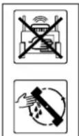
Uwaga -niebepezieansewozranienia!
J akumulator (RM 650 VE) 1
K Iadowarka (RM 650 VE) 1
RM650T, RM650V, RM650VE, RM650VS, RM655V, RM655VS, RM655YS:
RM 655 RS, RM 655 V, RM 655 VS, RM 655 YS:
A>1 mm
RM 655.1 RS, RM 655.0 V, RM 655.1 VS, RM 655.0 YS:
(RM 650 VS, RM 655 RS,
RM 655 VS, RM 655 YS) 390
Nastavitev bovdena pogona
(RM655YS) 390
Zmanjsanje obrabe in
preprecevanje okvar
Obicajni nadomestni deli 392
Izjava o skladnosti
RM 650 VS, RM 655 RS, RM 655 VS, RM 655 YS:

RM650T, RM650V, RM655V:

RM 655 RS, RM 655 V, RM 655 VS, RM 655 YS:
A>1 mm
Meritvo 2000/14/EC/S.I.2001/1701
Zagotovljena raven
Negotovost KpA 2 dB(A)
Vibracije dlan-roka
Navedena karakteristika vibriranja po standardu EN 12096:
Izmerjena vrednost
a_hw 3,80 m/s²
Negotovost Khw 1,90 m/s2
Meritev po EN ISO 5395-2, EN 20643
RM 650.0 V:
Oznaka tipa motorja Kohler HD775
znotranjim
zgorevanjem
Delovna prostornina 173 ccm
Zagonska naprava Zagon z vrvjo
Pogon rezalne letve trajen
Pogon na zadnja
kolesa Menjalnik Vario
Teza 46 kg
Posoda za gorivo 1,4 I
Emisije hrupa
Meritvo 2000/14/EC/S.l. 2001/1701:
Zagotovljena raven
Negotovost KpA 2 dB(A)
Vibracije dlan-roka
Navedena karakteristika vibriranja po
standardu EN 12096:
Izmerjena vrednost
a_hw 3.80 m/s²
Negotovost Khw 1,90 m/s²
Meritey po EN ISO 5395-2, EN 20643
RM 650.1 VE:
Oznaka tipa motorja EVC 300 E
z notranjim
zgorevanjem
Delovna prostornina 166 cm
Litij-ionska baterija in Glejt navodila
Negotovost KpA 2dB(A)
Vibraciè dlan-roka
Navedena karakteristika vibriranja po
standardu EN 12096:
Izmerjena vrednost
a_hw 3,00 m/s²
Negotovost Khw 1,50 m/s2
Meritev po EN ISO 5395-2, EN 20643
RM 650.0 VS:
Oznaka tipa motorja Kohler HD775
z notranjim
zgorevanjem
Delovna prostornina 173 ccm
Zagonska naprava Zagon z vrvjo
Pogon rezalne letve BBC
Pogon na zadnja
kolesa Menjalnik Vario
Teza 50kg
Posoda za gorivo 1,4
Emisije hrupa
Meritepo 2000/14/EC/S.l.2001/1701:
Zagotovljena raven
Negotovost KdA 2 dB(A)
Vibracije dlan-roka
Navedena karakteristika vibriranja po
standardu EN 12096:
Izmerjena vrednost
a_hw 3,80 m/s²
Negotovost Khw 1,90 m/s2
Meritve po EN ISO 5395-2, EN 20643
RM 655.1 RS, RM 655.0 V, RM 655.1 VS, RM 655.0 YS:
Serijska stevilka 6374
Sirina kosnje 53 cm
Rezalna naprava Rezalna letev
Stevilo vrtljajev
rezalne letve 2800 vrt/min
Visina kosnje 25 - 85 mm
Višina kosnje
(RM 655.1 RS) 20 - 80 mm
Zatezni moment
prirdlnegaavjaka za
noz 60-65Nm
Premer spednjih
koles 200 mm
Premer zadnjega
valja 90 mm
Prostornina kosare
701
Dolzina 171 cm
Sirina 59 cm
Višina 112 cm
RM 655.1 RS:
Pogon rezalne letve BBC
Pogon valja Menjalnik z eno prestavo
Teza 56 kg
Negotovost KwA xx dB(A)
Meritve po EN ISO 5395-2:
Raven zvočnega
tlaka na delovnem
mestu LpA 84 dB(A)
Negotovost KpA 2 dB(A)
Vibracije dlan-roka
Navedena karakteristika vibriranja po
standardu EN 12096:
Izmerjena vrednost
a_hw 2,80 m/s²
Negotovost Khw 1,40 m/s²
Meritey po EN ISO 5395-2, EN 20643
RM 655.0 V:
Pogon rezalne letve trajen
Pogon na zadnja
kolesa Menjalnik Vario
Teza 46 kg
Negotovost KpA 2 dB(A)
Vibracije dlan-roka
Navedena karakteristika vibriranja po
standardu EN 12096:
Izmerjena vrednost
a_hw 3,80 m/s²
Negotovost Khw 1,90 m/s2
Meritev po EN ISO 5395-2, EN 20643
RM 655.1 VS:
Pogon rezalne letve BBC
Pogon na zadnja
kolesa Menjalnik Vario
Teza 50 kg
Meritvo 2000/14/EC/S.I. 2001/1701:
Zagotovljena raven
Negotovost KpA 2 dB(A)
Vibracije dlan-roka
Navedena karakteristika vibriranja postandrodu EN 12096:
Izmerjena vrednost
a_hw 3,80 m/s²
Negotovost Khw 1,90 m/s2
Meritv po EN ISO 5395-2, EN 20643
RM 655.0 YS:
Pogon rezalne letve BBC
Pogon na zadnja Hidravlicni
kolesa menjalnik
Teža 56 kg
Meritvo 2000/14/EC/S.I. 2001/1701:
Zagotovljena raven
Negotovost KpA 2 dB(A)
Vibracijedlan-roka
Navedena karakteristika vibriranja po standardu EN 12096:
Izmerjena vrednost
a_hw 3.00 m/s²
Negotovost Khw 1.50 m/s²
Meritev po EN ISO 5395-2, EN 20643
Transport litij-ionskih baterij:
(RM 650 VS, RM 655 RS)
RM 655 VS, RM 655 YS) 416
Pohon kolies 416
(RM 650 VS, RM 655 RS,
RM 655 VS, RM 655 YS) 419
Nastavenie lanka pohonu kolies
(RM 655 YS) 419
Kontrola opotrebovania tecich list 419
RM 650 VS, RM 655 RS, RM 655 VS, RM 655 YS:
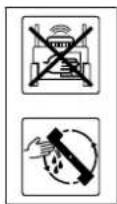
Pozor - Riziko poranenia!
Kym spalovacimotor pracije, nikdy nesiahajte do pracovneho priestoru rezného noza.
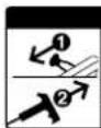
START/1
m = 311
#
17
-
-
12 =
13/14
1
1
#
#
#
1
1
图
F
。
引
…
1
#
1
#
m = 311
一
#
#
C
D
m = 311 ;
一
1
#
#
V
5
#
m = 311 ;
1
6
13/14
13/14
F
Hrubka noza A: >2,0 mm
RM 655 RS, RM 655 V, RM 655 VS, RM 655 YS:
A>1 mm
Trecie listy sa musia vymenit, ak su na spodnej strane stroja opotrebované az na hranicnú hodnotu, resp. ak uz uplne nezakryvaju zaciu skriu.
Meranie podla 2000/14/EC / S.I.
2001/1701:
Zaručená hladina
akustického vykonu
Meranie podla 2000/14/EC / S.I.
2001/1701:
Meranie podla 2000/14/EC / S.I. 2001/1701:
Meranie podla 2000/14/EC / S.I.
2001/1701:
Zaručená hladina
akustického vykonu
Meranie podla 2000/14/EC / S.I.
2001/1701:
Zaručená hladina
akustického vykonu
LwAd 98 dB(A)
Tolerancia KwA xx dB(A)
Meranie podla EN ISO 5395-2:
Hladina akustického
tlaku na pracovisku
LdA 84 dB(A)
Tolerancia K_pA 2 dB(A)
Vibracie na rukach/ramenach
Meranie podla 2000/14/EC / S.I.
2001/1701:
Zaručená hladina
akustického vykonu
LwAd 98 dB(A)
Tolerancia K WA 0,9 dB(A)
Meranie pod'ia EN ISO 5395-2:
Hladina akustického
tlaku na pracovisku
Meranie podla 2000/14/EC / S.I.
2001/1701:
Zaručená hladina
akustického vykonu
LwAd 98 dB(A)
Tolerancia KwA xx dB(A)
Meranie podla EN ISO 5395-2
Hladina akustického
tlaku na pracovisku
LdA 84 dB(A)
Tolerancia K_pA 2 dB(A)
Vibracie na rukach/ramenach
Bicak-Fren-Kavramasi (BBC) 442
Bicak-fren-kavramasi (RM 650 VS, RM 655 RS, RM 655 VS, RM 655 YS)
Kablo aqi paketli makine unitesini ayarlayin (RM 655 YS) 448
Koruyucu cta a sinma kontrlu 448
Saklama ve uzun sureli mola (kis molasi) 448
Nakliye 449
Nakliye 449
Cevrekoruma 449
Asinmanin en aza indirgenmesi ve
RM 650 VS, RM 655 RS, RM 655 VS, RM 655 YS:

RM650T, RM650V, RM655V:
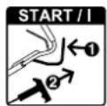
Benzinl motoru calistirma
5 B Içak kavrama kolu (RM 650 VS, RM 655 RS, RM 655 VS, RM 655 YS)
6 Ma r s dugmesi (RM 650 VE)
9.3 Gidonun ayarlanmasi

14.10 Bicak-fren-kavramasi (RM 650 VS, RM 655 RS, RM 655 VS, RM 655 YS)
Bakim araligi:
Yildabirkez
RM 655 RS, RM 655 V, RM 655 VS, RM 655 YS:
A>1 mm
Bicak sutunatahriksurekli
Arka tekerlek tahriki Vario sanziman
Aigrlk 44 kg
Yakit deposu 0,91
Gurultu emisyonlari
2000/14/EC / S.I. 2001/1701 uyarinca olcum:
Garanti edilen
RM 655.1 RS, RM 655.0 V, RM 655.1 VS, RM 655.0 YS:
Serinumarasi6374
Kesim genisiigi 5 3
Bicak sutunatahriki surekli
Arka tekerlek tahriki Vario sanziman
Aigrlik 46 kg
Benzinli motor
yapi turu 4-Zamanlbenzinli motor
Uretici, tip Kohler HD775
Silindir hacmi 173 ccm
Start mekanizmasi Telle motor startu
Nominal hiz
sayisinda nominal 2,6-2800
guc kW - dev/dak
Yakit deposu 1,4 I
Gürültu emisyonlari
Ölçüm kriteri 2000/14/EC / S.I.
2001/1701:
Ölçüm kriteri 2000/14/EC / S.I.
2001/1701:
Garanti edilen
Ölcüm kriteri 2000/14/EC / S.I.
2001/1701:
Garanti edilen
- STIHL RM 650 T, RM 650 V, RM 650 VE, RM 650 VS RM 655 RS, RM 655 V, RM 655 VS, RM 655 YS
- STIHL
- RM 650 VS, RM 655 RS, RM 655 VS,
- RM 650 VS, RM 655 YS:
- RM650T, RM650V, RM650VE, RM650VS;
- A>8mm
- RM 655 RS, RM 655 V, RM 655 VS, RM 655 YS:
- A>1 mm
- RM 655.1 RS, RM 655.0 V, RM 655.1 VS, RM 655.0 YS:
- Table of contents
- Notes on the instruction manual 44
- Machine overview 45
- For your safety 45
- Description of symbols 52
- Standard equipment 53
- Preparing the machine for operation 53
- Controls 54
- Safety devices 56
- Blade brake clutch (BBC) 56
- Notes on working with the machine 56
- Operating the machine 57
- Maintenance 59
- Notes on the instruction manual
- General
- Instructions for reading the instruction manual
- Viewing direction:
- Section reference:
- Designation of text passages:
- Texts with added significance:
- Danger
- Warning
- Caution
- Note
- Texts relating to illustrations:
- Lawn mower with blade brake clutch, BBC
- Risk of injury!
- Machine overview
- For your safety
- General
- Risk of death from suffocation!
- Caution - risk of accident!
- Caution! Danger to health due to vibrations. Excessive exposure to vibrations can result in damage to the
- Refilling the tank - handling petrol
- Danger to life!
- Do not overfill the fuel tank!
- Battery and charger
- Clothing and equipment
- Transporting the machine
- Before operation
- During operation
- Exhaust gases:
- Starting:
- Working on slopes:
- Working:
- Risk of stumbling!
- Maintenance and repairs
- Caution - risk of injury!
- Risk of injury due to the mowing blade!
- Cleaning:
- Maintenance operations:
- Storage for prolonged periods without operation
- Disposal
- Description of symbols
- Attention!
- Caution!
- Throttle setting
- RM 650 VE:
- Setting the driving speed
- Standard equipment
- Item Designation Qty.
- Preparing the machine for operation
- General
- Assembling the handlebar
- Attaching cables:
- Avoid damage to the machine!
- Attaching and detaching the recoil starter rope
- Attaching:
- Detaching:
- Installing the grass catcher box
- Inserting the mulch insert:
- Controls
- General
- Removing and inserting the mulch insert
- Removing the mulch insert:
- Fuel and engine oil
- Engine oil:
- Fuel:
- Controls on the handlebar
- Adjusting the handlebar
- Danger of pinching!
- Working position:
- Height adjustment:
- Central cutting height adjustment
- RM 655 RS:
- Battery and charger (RM 650 VE)
- Initial operation:
- Removing and inserting the battery:
- Level indicator
- A Grass catcher box is being filled
- Grass catcher box is filled
- Attaching and detaching the grass catcher box
- Safety devices
- Safety devices
- Motorstop lever
- Measuring the run-on time
- Blade brake clutch (BBC)
- Two-hand operation:
- Integrated blade run-down brake:
- Notes on working with the machine
- A perfect, thick lawn is achieved by
- Working area for operator
- Lawn mower with lawn roller
- Applications
- How should mulching be performed?
- Operating the machine
- Checking the blade brake clutch
- Starting the engine (RM 650 T, RM 650 V, RM 655 V)
- Starting the engine (RM 650 VE)
- Stopping the engine (RM 650 T, RM 650 V, RM 650 VE, RM 655 V)
- Starting the engine (RM 650 VS, RM 655 RS, RM 655 VS, RM 655 YS)
- Engaging the mowing blade (RM 650 VS, RM 655 RS, RM 655 VS, RM 655 YS)
- Disengaging the mowing blade (RM 650 VS, RM 655 RS, RM 655 VS, RM 655 YS)
- Stopping the engine (RM 650 VS, RM 655 RS, RM 655 VS, RM 655 YS)
- Self-propulsion
- 4,2 km/h
- Switching on self-propulsion:
- Setting the drive speed:
- Switching off self-propulsion:
- Emptying the grass catcher box
- Maintenance
- General
- Annual service by the specialist dealer:
- Cleaning the machine
- Cleaning position:
- Notes on cleaning:
- Checking blade wear
- Maintenance interval:
- Before each use
- Removing and installing the blade
- Removing the blade:
- Installing the blade:
- Sharpening the mowing blade
- Sharpening instructions:
- Engine
- General information:
- Battery and charger maintenance
- Wheels and gearbox
- Lawn roller maintenance
- Maintenance interval: Once annually or as required
- Maintenance interval: Once a year
- Adjusting the selfpropulsion cable (RM 655 YS)
- Maintenance interval: Prior to initial use or as required
- Adjusting the cable
- Checking skirting protector wear
- Storage and periods of inoperation (winter break)
- Transport
- Transport
- Carrying the machine:
- Securing the machine (lashing):
- Environmental protection
- Li-lon
- Minimising wear and preventing damage
- Important information on maintenance and care of the product group petrol lawn mowers (STIHL RM)
- Wearing parts
- Compliance with the information in this instruction manual
- Maintenance operations
- Standard spare parts
- Declaration of conformity
- RM 650.0 T, RM 650.0 V, RM 650.0 VS
- RM 650.1 VE
- RM 655.0 V
- RM 655.1 RS, RM 655.1 VS
- RM 655.0 YS
- RM 650.0 T, RM 650.0 V
- Technical specifications
- Engine
- RM 650.0 T:
- Sound emissions
- Hand-arm vibrations
- RM 650.0 V:
- RM 650.1 VE:
- RM 650.0 VS:
- RM 655.1 RS:
- RM 655.0 V:
- RM 655.1 VS:
- RM 655.0 YS:
- Transporting lithium-ion batteries:
- REACH
- Troubleshooting
- Fault:
- Possible cause:
- Remedy:
- Fault: Excessive vibration during operation
- Service schedule
- Handover confirmation
- Service confirmation
- Chere clientele, cher client,
- RM 650 VS, RM 655 RS, RM 655 VS, RM 655 YS:
- RM 655.1 RS, RM 655.0 V, RM 655.1 VS, RM 655.0 YS :
- Duwstang instellen
- Gevaar op klemmen!
- Vibrations hand-arm
- Staffa trazione
- Embrague-freno de cucilla (BBC) 180
- RM650T, RM650V, RM655V:
- Acoplar la cucilla (RM 650 VS, RM 655 RS, RM 655 VS, RM 655 YS)
- Desacoplar la cucilla (RM 650 VS, RM 655 RS, RM 655 VS, RM 655 YS)
- Embrague-freno de cucilla (RM 650 VS, RM 655 RS, RM 655 VS, RM 655 YS)
- Gassregulating
- Knivclutch (RM 650 VS, RM 655 RS, RM 655 VS, RM 655 YS)
- Produsentensamsvarserklaering
- Varning - risk for olycksfall!
- Forbränningsmotor
- Transport of maskinen
- Risiko for at snuble!
- OBS - risiko for kvaestelser!
- Hand-arm vibrationer
- Transport of lithium battery:
- Uwaga -niebepezieansewozranienia!
- Vibracije dlan-roka
- Emisije hrupa
- Vibraciè dlan-roka
- Transport litij-ionskih baterij:
- Pozor - Riziko poranenia!
- START/1
- m = 311
- #
- 17
- -
- =
- 13/14
- 1
- 图
- F
- 。
- 引
- …
- 一
- C
- D
- m = 311 ;
- V
- 5
- 6
- Hrubka noza A: >2,0 mm
- Bicak-Fren-Kavramasi (BBC) 442
- Gidonun ayarlanmasi
- Gurultu emisyonlari
- Benzinli motor
- Gürültu emisyonlari
Brand : STIHL
Model : RM 650 VE
Category : Lawn mower