
RFEV 19125 RT - Milling machine METABO - Free user manual and instructions
Find the device manual for free RFEV 19125 RT METABO in PDF.
| Product type | Renovation router |
| Brand | Metabo |
| Model | RFEV 19125 RT |
| Nominal power input | 1700 W |
| Max. no-load speed | 19000 rpm |
| Speed adjustment | Electronic, adjustment wheel |
| Mains voltage | 230 V / 50 Hz |
| Weight (without cable) | 5.5 kg |
| Protection class | II |
| Main functions | Milling plaster, adhesive residues, formwork transitions; grinding concrete surfaces |
| Cutter type | Interchangeable milling discs |
| Compatible accessories | Diamond cup wheel, milling head |
| Dust extraction system | Connectable to a class M vacuum cleaner via hose (8) |
| Protective cover | Yes, depth adjustable |
| Additional handle | Adjustable stirrup handle |
| Spindle lock | Yes, for tool change |
| Safety | Restart protection, emergency stop, dead man's switch |
| Maintenance | Regular cleaning of ventilation slots by blowing dry air |
| Repairability | Spare parts available on metabo.com; repair by authorized service |
Frequently Asked Questions - RFEV 19125 RT METABO
User questions about RFEV 19125 RT METABO
0 question about this device. Answer the ones you know or ask your own.
Ask a new question about this device
Download the instructions for your Milling machine in PDF format for free! Find your manual RFEV 19125 RT - METABO and take your electronic device back in hand. On this page are published all the documents necessary for the use of your device. RFEV 19125 RT by METABO.
USER MANUAL RFEV 19125 RT METABO
Chief Technology Officer Koki Holdings Co., Ltd.
*4) Metabowerke GmbH - Metabo-Allee 1 - 72622 Nuertingen, Germany
DEUTSCHde
Original instructions
1. Declaration of Conformity
Under our sole responsibility, we hereby declare that these renovation routers, identified by type and serial number 1), comply with all relevant requirements of the directives 2) and standards 3) and technical documents for 4)- see page 3.
For UK only:
UK We as manufacturer and authorized person to compile the technical file, see *4) on page 3, hereby declare under sole responsibility that these renovation routers, identified by type and serial number *1) on page 3, fulfill all relevant provisions of following UK Regulations S.I. 2016/1091, S.I. 2008/ 1597,S.I.2012/3032 and Designated Standards see *3) on page 3.
2. Specified Use
When fitted with original Metabo accessories, the renovation router is suitable for the following tasks:
... Removing plaster, old tile adhesive and paintwork,
... Milling off formwork transitions,
... Roughing concrete surfaces
Also suitable for grinding surfaces with diamond cup wheels
Do not use for abrasive cutting-off operations, roughing work, sanding, polishing or flap disc work.
The machine must not be used with water.
It is suitable for commercial use in trade and industry.
Always use a suitable dust extraction system: Connect an M-class vacuum cleaner to the extractor connection piece (8).
The user bears sole responsibility for any damage caused by improper use.
Generally accepted accident prevention regulations and the enclosed safety information must be observed.
3. General safety instructions

For your own protection and for the protection of your power tool, pay attention to all parts of the text that are marked with this symbol!

WARNING - Read the operating instructions to reduce the risk of injury.

WARNING - Read all safety warnings, instructions, illustrations and
specifications provided with this power tool. Failure to follow all instructions listed below may result in electric shock, fire and/or serious injury.
Save all warnings and instructions for future reference.
Always include these documents when passing on your power tool.
4. Special Safety Instructions
4.1 General safety instructions for routing and grinding:
a) This power tool is designed for surface routing or grinding. Read all safety warnings, instructions, illustrations and specifications provided with this power tool. Failure to follow all instructions listed below may result in electric shock, fire and/or serious injury.
b) Operations such as sanding, wire brushing, polishing, hole cutting or cutting-off are not recommended to be performed with this power tool. Operations for which the power tool was not designed may create a hazard and cause personal injury.
c) Do not convert this power tool to operate in a way which is not specifically designed and specified by the tool manufacturer. Such a conversion may result in a loss of control and cause serious personal injury.
d) Do not use accessories which are not specifically designed and specified by the tool manufacturer. Just because the accessory can be attached to your power tool, it does not assure safe operation.
e) The rated speed of the accessory must be at least equal to the maximum speed marked on the power tool. Accessories running faster than their rated speed can break and fly apart.
f) The outside diameter and the thickness of your accessory must be within the capacity rating of your power tool. Incorrectly sized accessories cannot be adequately guarded or controlled.
g) The dimensions of the accessory mounting must fit the dimensions of the mounting hardware of the power tool. Accessories that do not match the mounting hardware of the power tool will run out of balance, vibrate excessively and may cause loss of control.
h) Do not use a damaged accessory. Before each use inspect the accessory such as abrasive wheels for chips and cracks, backing pad for cracks, tear or excess wear, wire brush for loose or cracked wires. If power tool or accessory is dropped, inspect for damage or install an undamaged accessory. After inspecting and installing an accessory, position yourself and bystanders away from the plane of the rotating accessory and run the power tool at maximum no-load speed for one minute. Damaged accessories will normally break apart during this test time.
i) Wear personal protective equipment. Depending on application, use face shield, safety goggles or safety glasses. As appropriate, wear dust mask, hearing protectors, gloves and workshop apron capable of stopping small abrasive or workpiece fragments. The eye protection must be
ENGLISHen
capable of stopping flying debris generated by various applications. The dust mask or respirator must be capable of filtrating particles generated by the particular application. Prolonged exposure to high intensity noise may cause hearing loss.
j) Keep bystanders a safe distance away from work area. Anyone entering the work area must wear personal protective equipment. Fragments of workpiece or of a broken accessory may fly away and cause injury beyond immediate area of operation.
k) Hold the power tool by insulated gripping surfaces only, when performing an operation where the cutting accessory may contact hidden wiring or its own cord. Contact with a "live" wire will also make exposed metal parts of the power tool "live" and could give the operator an electric shock.
1) Position the cord clear of the spinning accessory. If you lose control, the cord may be cut or snagged and your hand or arm may be pulled into the spinning accessory.
m) Never lay the power tool down until the accessory has come to a complete stop. The spinning accessory may grab the surface and pull the power tool out of your control.
n) Do not run the power tool while carrying it at your side. Accidental contact with the spinning accessory could snag your clothing, pulling the accessory into your body.
o) Regularly clean the power tool's air vents. The motor's fan will draw the dust inside the housing and excessive accumulation of powdered metal may cause electrical hazards.
p) Do not operate the power tool near flammable materials. Sparks could ignite these materials.
q) Do not use accessories that require liquid coolants. Using water or other liquid coolants may result in electrocution or shock.
4.2 Kickback and related warnings
Kickback is a sudden reaction to a pinched or snagged rotating wheel, backing pad, brush or any other accessory. Pinching or snagging causes rapid stalling of the rotating accessory which in turn causes the uncontrolled power tool to be forced in the direction opposite of the accessory's rotation at the point of the binding.
For example, if an abrasive wheel is snagged or pinched by the workpiece, the edge of the wheel that is entering into the pinch point can dig into the surface of the material causing the wheel to climb out or kick out. The wheel may either jump toward or away from the operator, depending on direction of the wheel's movement at the point of pinching. Abrasive wheels may also break under these conditions.
Kickback is the result of power tool misuse and/or incorrect operating procedures or conditions and can be avoided by taking proper precautions as given below.
a) Maintain a firm grip with both hands on the power tool and position your body and arms to allow you to resist kickback forces. Always use auxiliary handle, if provided, for maximum control over kickback or torque reaction during start-up. The operator can control torque reactions or kickback forces, if proper precautions are taken.
b) Never place your hand near the rotating accessory. Accessory may kickback over your hand.
c) Do not position your body in the area where power tool will move if kickback occurs. Kickback will propel the tool in direction opposite to the wheel's movement at the point of snagging.
d) Use special care when working corners, sharp edges etc. Avoid bouncing and snagging the accessory. Corners, sharp edges or bouncing have a tendency to snag the rotating accessory and cause loss of control or kickback.
e) Do not attach a saw chain woodcarving blade, segmented diamond wheel with a peripheral gap greater than 10mm or toothed saw blade. Such blades create frequent kickback and loss of control.
4.3 SafetyWarnings Specific for Routing Operations:
a) Use only routing tools that are recommended for your power tool and the specific guard designed for these routing tools. Routing tools that are not designed for use with the power tool cannot be guarded properly and are unsafe.
b) The guard must be securely attached to the power tool and positioned so as to minimise exposure of the routing body to the operator and thus maximise safety. The guard helps to protect the operator from broken fragments, accidental contact with the routing body and sparks that could ignite clothing.
c) Do not work on surfaces with exposed steel reinforcements or similar. Doing so may result in kickback or loss of control over the power tool.
d) Before commissioning, check that the routing wheels can move freely. Clean these, if necessary.
e) Do not use damaged routing wheels.
f) Exercise particular caution when working on corners, edges and ledges. There is a risk here of kickback or damaging the router.
g) Routing wheels have sharp edges and may be very hot after use. Caution! Risk of injury.
4.4 SafetyWarnings Specific for Grinding with Diamond Cup Wheels:
a) Use only wheel types that are recommended for your power tool and the specific guard designed for the selected wheel. Wheels for which the power tool was not designed cannot be adequately guarded and are unsafe.
b) The guard must be securely attached to the power tool and positioned for maximum safety, so the least amount of wheel is exposed
towards the operator. The guard helps to protect the operator from broken fragments, accidental contact with the wheel and sparks that could ignite clothing.
c) Wheels must be used only for recommended applications.
d) Always use undamaged wheel flanges that are the correct size and shape for your selected accessories. The correct flanges support the accessories.
4.5 Additional Safety Instructions

WARNING - Always wear protective goggles.

Wear a suitable dust protection mask.

Wear ear protectors.

WARNING - Always operate the power tool with two hands.
Use elastic cushioning layers if they have been supplied with the sanding media and if required.
Observe the specifications of the accessory manufacturer! Protect the accessories from grease and physical impact.
Accessories must be stored and handled with care in accordance with the manufacturer's instructions.
The workpiece must lay flat and be secured against slipping, e.g. using clamps. Large workpieces must be supported adequately.
If accessories with threaded inserts are used, the end of the spindle may not touch the base of the hole on the grinding tool. Make sure that the thread in the accessory is long enough to accommodate the full length of the spindle. The thread in the accessory must match the thread on the spindle. See page 3 and chapter 15. Technical Specifications for more information on the spindle length and thread.

Impurities that manage to enter the machine may block the switching
mechanism. This is why, when the machine is running, it is necessary to blow compressed air through the rear ventilation slots of the machine regularly, frequently and thoroughly. The machine must be held firmly in this case.
Damaged, eccentric or vibrating tools must not be used.
Avoid damage to gas or water pipes, electrical cables and load-bearing walls (building structure).
Pull the plug out of the socket before making any adjustments, converting or servicing the machine.
A damaged or cracked side handle must be replaced. Never operate the machine with a defective additional handle.
A damaged or cracked safety guard must be replaced. Never operate a machine with a defective safety guard.
Only use accessories that are surmounted by brushes of the safety guard.
Only use the guard supplied: The wrong guard can lead to loss of control, insufficient shielding, increased risk from dust exposure and serious injury.
Use authorised tools only.
Reducing dust exposure:
WARNING - Some dust created by power sanding, sawing, grinding, drilling, and other construction activities contains chemicals known to cause cancer, birth defects or other reproductive harm. Some examples of these chemicals are:
- Lead from lead-based paints,
- Crystalline silica from bricks and cement and other masonry products, and
- Arsenic and chromium from chemically treated lumber.
Your risk from these exposures varies, depending on how often you do this type of work. To reduce your exposure to these chemicals: work in a well ventilated area, and work with approved safety equipment, such as those dust masks that are specially designed to filter out microscopic particles.
This also applies to dust from other materials such as some timber types (like oak or beech dust), metals, asbestos. Other known diseases are e.g. allergic reactions, respiratory diseases. Do not let dust enter the body.
Observe the relevant guidelines and national regulations for your material, staff, application and place of application (e.g. occupational health and safety regulations, disposal).
Collect the particles generated at the source, avoid deposits in the surrounding area.
Use suitable accessories for special work. In this way, fewer particles enter the environment in an uncontrolled manner.
Use a suitable extraction unit.
Reduce dust exposure with the following measures:
- do not direct the escaping particles and the exhaust air stream at yourself or nearby persons or on dust deposits,
- use an extraction unit and/or air purifiers,
- ensure good ventilation of the workplace and keep clean using a vacuum cleaner. Sweeping or blowing stirs up dust.
- Vacuum or wash the protective clothing. Do not blow, beat or brush.
5. Overview
See page 2.
1 Bar auxiliary handle *
2 Thumb screws of the bar auxiliary handle *
3 Locking discs of the bar auxiliary handle *
4 Threaded holes on gear housing
5 2-hole spanner
ENGLISHen
6 Routing tool*
7 Spindle
8 Extractor connection piece
9 Spindle locking button
10 Clamping nut *
11 Diamond cup wheel
12 Support flange *
13 Screw
14 Safety disc
15 Electronic signal indicator
16 Speed adjustment wheel
17 Trigger switch
18 Handle
19 Safety guard
20 Flat area for working close to edges
21 Wing nut
22 Depth stop
depending on equipment/not in scope of delivery
6. Initial Operation

Before plugging in the device, check that the rated mains voltage and mains frequency, asified on the rating label, match your power supply.

Australia: Always use a residual current device (RCD) protected supply with a rated residual extent of 30mA or less.
6.1 Fitting of bar auxiliary handle

Always work with the bar auxiliary handle (1) attached! Fit the bar auxiliary handle as shown illustration A, page 2).
- Fit locking discs (3) to the left and right of the gear housing.
- Fit the bar auxiliary handle (1) at the gear housing.
- Insert the thumb screws (2) left and right in bar auxiliary handle (1) and turn gently.
- Adjust the bar auxiliary handle (1) to the required angle.
- Firmly tighten the thumb screws (2) to the left and right manually.
6.2 Adjusting the depth stop

For safety reasons, only use the safety guard (19) provided.
See figure, page 2.
- Release wing screw (21).
- Twist the depth stop (22) to adjust the height in relation to the accessory and the work task.
- Hand-tighten the wing screw (21) securely.
6.3 Dust extraction

Always use a suitable dust extraction system: Connect an M-class vacuum cleaner to theactor connection piece (8).
For optimal dust extraction, use the connecting sleeve 6.30796.
We recommend using an antistatic suction hose with diameter 35mm
7. Attaching the accessory

Disconnect the mains plug before changing any accessories. The machine must be
switched off and the spindle must be at a standstill.
7.1 Locking the spindle

Press in the spindle locking knob (9) only when the spindle is stationary!
- Press in the spindle locking button (9) and turn the spindle (7) by hand until you feel the spindle locking button engage.
7.2 Fitting/removing the routing tool

For safety reasons, use the safety guard (19) with the attached depth stop (22).
See illustration B on page 2.
To fit:
- Lock the spindle (see chapter 7.1).
- Screw on and tighten the routing tool (6) using the 2-hole spanner (5) in a clockwise direction.
To remove:
- Lock the spindle (see chapter 7.1). Unscrew the routing tool (6) with the 2-hole spanner (5) in an anticlockwise direction.
7.3 Fitting/removing the diamond cup wheel

For safety reasons, use the safety guard (19) with the attached depth stop (22).
See illustration C on page 2.
To fit:
- Fit the support flange (12) on the spindle. (7) The flange should not turn on the spindle when properly attached.
- Lay the diamond cup wheel (11) on the support flange (12) so that it lies flat along the support flange.
- The 2 sides of the clamping nut (10) are different. Screw the clamping nut onto the spindle so that the band of the clamping nut (10) is facing upward.
- Lock the spindle (see chapter 7.1). Turn the clamping nut (10) clockwise using the 2-hole spanner (5) to secure.
To remove:
- Lock the spindle (see chapter 7.1). Turn the clamping nut (10) anticlockwise using the 2-hole spanner (5) to unscrew.
8. Use
8.1 Setting speed
Set the optimum speed on the setting wheel (16), depending on the application.
8.2 Switching On and Off

Always guide the machine with both hands.

Switch on first, then guide the accessory towards the workpiece.

The machine must not be allowed to draw in additional dust and shavings. When switching
the machine on and off, keep it away from dust deposits. After switching off the machine, only place it down when the motor has come to a standstill.
Avoid inadvertent starts: always switch the tool off when the plug is removed from the mains socket or if there has been a power cut.
In continuous operation, the machine continues running if it is forced out of your hands. Therefore, always hold the machine with both hands using the handles provided, stand in a safe position and concentrate.
Machines with the designation W...RT: Torque activation (with dead man's lever)
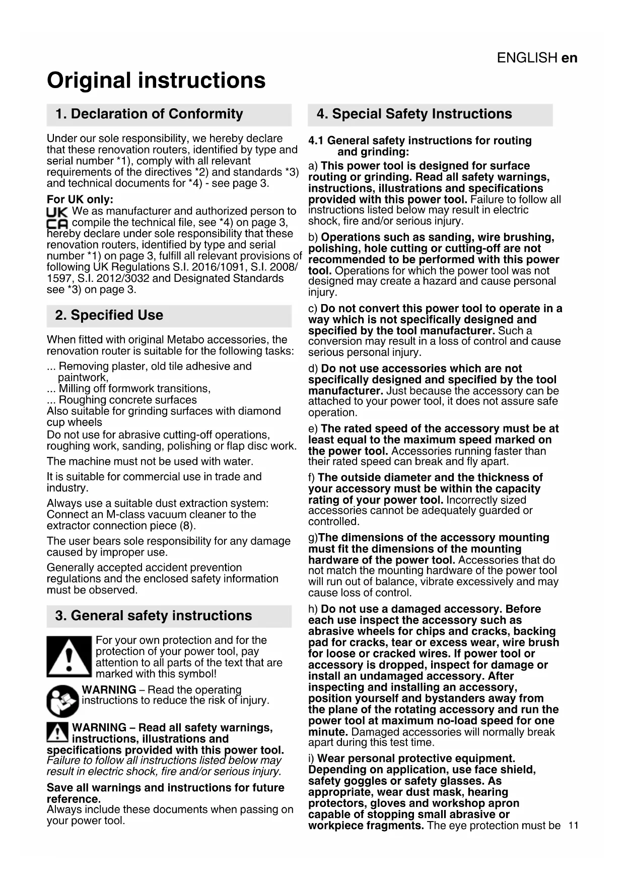
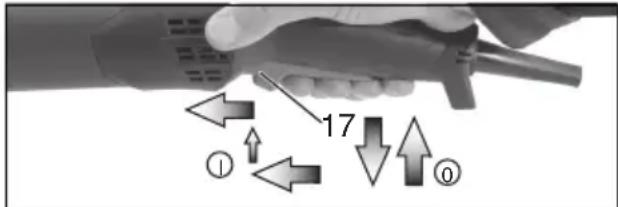
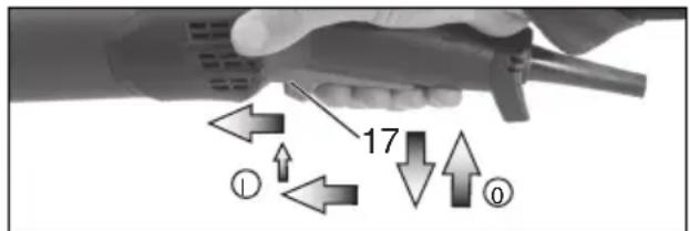
Switching on: Slide the trigger switch (17) forwards and then push the trigger switch (17) upwards.
Switching off: Release the trigger switch (17).
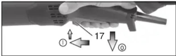
Machines with the designation W...RT: Continuous operation (depending on features)
Switching on: Switch the machine on as described above. Now slide the trigger switch (17) forwards again and release in the front position to lock the trigger switch (17) (continuous operation).
Switching off: Push the trigger switch (17) upwards and release.
8.3 Working Directions
Surface routing and grinding:
Place the machine with the entire surface of the tool onto the workpiece. Apply moderate pressure and move it to and fro across the surface.
9. Maintenance
Replace worn or damaged routing wheels (see figure, page 2):
- Removing the routing tool (see chapter 7.2).
- Extract the screw (13) in an anticlockwise direction. Remove the safety disc (14).
- Replace all routing wheels as shown.
(Always use the same type of routing wheels).
Reassemble all parts as shown.
Insert and turn the screw (13) in a clockwise direction and tighten with 13Nm± 1Nm
10. Cleaning
Cleaning the motor: It is possible that particles deposit inside the power tool during operation. This impairs the cooling of the power tool.
The power tool should be cleaned regularly, often and thoroughly through all front and rear air vents using a vacuum cleaner or by blowing in dry air.
Prior to this operation, separate the power tool from the power source and wear protective glasses and a suitable dust mask. Ensure appropriate suction is available when blowing out vents.
11. Troubleshooting
Machines with VTC and TC electronics:
The electronic signal display lights up and the load speed decreases (not W...RT). (15) There is too much load on the machine! Run the machine in idling until the electronics signal indicator switches off.
The machine does not start. The electronic signal display (15) (depends
on model) flashes. The restart protection is active. If the mains plug is inserted with the machine switched on, or if the power supply is restored following an interruption, the machine does not start up. Switch the machine off and on again.
12. Accessories
Use only genuine Metabo accessories.
Use only accessories that fulfil the requirements and specifications listed in these operating instructions.
Always use the suitable tool and the supplied guard for the application.
Task: Routing
- Tool: Routing head
Task: Surface grinding
- Tool: "Masonry/concrete" diamond cup wheel
Work only with appropriate dust extraction: connect an all-purpose vacuum cleaner class M to the extractor connection piece.
For a complete range of accessories, see www.metabo.com or the catalogue.
13. Repairs
Repairs to electrical tools must be carried out by qualified electricians ONLY!
A defective mains cable must only be replaced with a special, original mains cable from metabo, which is available only from the Metabo service.
If you have Metabo electrical tools that require repairs, please contact your Metabo service centre. For addresses see www.metabo.com.
You can download spare parts lists from www.metabo.com.
14. Environmental Protection
The sanding dust generated may contain hazardous materials: do not dispose of this dust with household waste, but at a special collection point for hazardous waste.
Observe national regulations on environmentally compatible disposal and on the recycling of disused machines, packaging and accessories.
Packaging materials must be disposed of according to their labelling in accordance with municipal guidelines. Further information can be found at www.metabo.com in the "Service" section.

Only for EU countries: Never dispose of power tools in your household waste! In accordance with European Guideline 2012/
19/EU on used electronic and electric equipment and its implementation in national legal systems, used power tools must be collected separately and handed in for environmentally compatible recycling.
15. Technical specifications
Explanation of details on page 3. Subject to change in line with technical advances.
D_max = max diameter of accessory
t_,1 = Max. permitted thickness of clamping shank on accessory when using clamping nut (10)
M = Spindle thread
I = Length of the grinding spindle
n^* = No-load speed (maximum speed)
P1 = Nominal power input
P2 = Power output
m = Weight without mains cable
Measured values determined in conformity with EN 62841.
Machine in protection class II
Alternating current
- Energy-rich, high-frequency interference can cause fluctuations in speed. However, the fluctuations disappear as soon as the interference fades away.
The technical specifications quoted are subject to tolerances (in compliance with the relevant valid standards).
A Emission values
Using these values, you can estimate the emissions from this power tool and compare these with the values emitted by other power tools. The actual values may be higher or lower, depending on the particular application and the condition of the tool or power tool. In estimating the values, you should also include work breaks and periods of low use. Based on the estimated emission values, specify protective measures for the user - for example, any organisational steps that must be put in place.
Vibration total value (vector sum of three directions) determined in accordance with EN 62841:
a_hV = Vibration emission level (grinding)
K_n, = Uncertainty (vibration)
Typical A-effective perceived sound levels:
LpA =Sound pressure level
During operation the noise level can exceed 80 dB(A).
! Wear ear protectors!
K_h, = incertitude (vibration)
8.1 Stille inn turtall
n^* = Tomgangsturtall (hoyeste turtall)
P1 = Nominelt effektopptak
P_2 =Avgitt effekt
a_hV = Vibrationsemission (slibning)
K_n, = Usikkerhed (vibration)
BnKIOUHOIBy BNKOpNCaHNa 6e3 BoDn
IhCTpyMeHT npn3HaueHn dJa KOMepuiHoro BnKOpNCtAHnB B IpomncIOBOcTi Ta B npNBaTHOMy BnPo6HnTBI.
PobToBnKHOyBaTHNIIuE3BiINOBiHIM npIcTpoEmIJIaBaNLeHHNlNyPiI'EDHaTH NIOLOOCIJIaBdAJeHHNlNyKnacyMdo BCMOKTyBaJIbHOrO NaTppy6Ka (8).
3a noiKoJKeHH, BnHInKaHi eKcNlyaTaueio He 3a npn3HaueHHaM, Hece BiDIOBiaIbHicTb BnKlIOUHO KOpNCyBaH.
Heo6xidno DoTpmyBaTncb 3araIbHOpnHrTnx npabnl 3anobiraHHa HeuacnM BnnaKaM, a TAKoK npabnil TexhIKI 6e3neKN, HabeJeHX B ciN IHCTpyKcii.
3. 3araJIbHI npaBnlaTexHikn6e3neKn

3aJy BaWoi 6e3neKn Ta 3axNCTy eJeKTpoIHCTpyMeHTa BiD NOwKOdHeHb DoTPmMyTEcB BkA3iBOK, No3HaueHnx CUMCMBOLOM!

NONEPEKHEHHA 3 METOIO 3HNKHeHHa pN3NKy OTpIMaHHa TpaBM npoHTaIte cHIO IHCTpyKcHIO 3 ekCnlyaTauii.

PONEPEDHEHHI - PpoHTaTe Bci Bha3IBHn 3 TexHikn 6e3neHn, IHcTpHuCii, cTpaCi Ta CneuNphiAcii, HadaHI 3 cIMM XtpoHCTpyMeHToM. HeBnKoHaHHYycix
HaBeHeHx HnKHe IHCTpyKuIM MOKe np3BecTIO ypaKeHH eJeHTpHuHM CTPyMOM, NOHeHi Ta/a60 TAAKNX TpaBM.
36epiraTe npaBnla Ta Bha3iBn 3 TexhiHn
6e3neKn JIA Ma6yThbOro BHKOpNCtAHHa.
IpepeabaIte BaW eJNTpoIHCTpyMeHT TlbKn pa30M 3 cIMN DOKymeHTAmN.
4. CneuiaJIbHi npaBnla texHikn 6e3neKn
4.1 3araJIbHI BHa3iBHN 3 TexHIKI 6e3neHH npn fpe3epyBaHHI Ta wJlifyBaHHI:
a) LcE eIeKtpoiHCTpyMeHT npn3HaueHn dJIa Phpe3epyBaHH a60 wJiΦyBaHH NOBepxOHb. IpouHTaIte yci npabHla texhIKN 6e3neH, IHCTpyHcii, 3o6paKeHH Ta daHI, OTPMaHi pa3OM 3 cIM IHCTpyMeHTom. HeDToPMaHH HaBeDeHnx HnKHe BkA3IBOK MOKe npn3BecTN Do UpaKaHeHH eIeKTPnuHm CTpyMOM, NOnKeHt Ta/a60 TAAHHX TpaBM.
b) LcE eIeKtpoiHCTpyMeHT He npn3HaueHn dIra wIiΦyBaHH nanepoBOU wIiΦyBaJIbHOIO Wkypko, BnKOHaHH po6it i3 dpOTAHm uithamn, noIpyBaHH, Bnpi3aHH OTBOPIB Ta a6pa3NBHO BIDpi3aHH. BnKOpNCtAHn eIeKtpoiHCTpyMeHTa He 3a npn3HaueHHM MoJHe npn3BecTn Do NOwKOJKeHb Ta TpaBM.
c) 3a6bOpOHeHO BnKOpNCTOBByBaTH eIeHTpOiHCTpyMeHT dJIa BnKoHaHHaФyHHciI, dJIa YHKx IORO CneuaJIbHO He cKOHCTpyNoBAHO Ta aKI He nepeD6aueHO NOro BnPo6HnKOM. Take nepeo6laJaHaHHaMOKe npu3BeCTn Do BTPaTI KepyBaHHaTa TjaKKNX TpaBM.
d) 3a6bOpOHeHO BnKOpNCToBvBaTH iNCTpyMeHTaJIbHI HacaIHy,ЯH He 6yIoopeIb6aueHO Ta peKOMeHDoBaHO BnPo6HHo IJIy BiINOBiDHorO eIeKtpoiHcTpyMeHTa. TIIbKn Te,Io npHaIaIy niIXoIITb Do eIeKtpoIHcTpyMeHTa, He rapaHTye 6e3neUHe BnKOpNCtaHHJ.
e)Донустma кьбICTb 66epTIB INCTpyMeHTaIbHOi HacaHNe He NOBHHa 6yTH MeHwe Bha3aHOi Ha eJeKtpoIHcTpymEHTI MaHCmMaIbHOi KIIbKOCTi 66epTIB. IHCTpyMeHTaIbHa Hacadka,Як aOBepTaEcTbcr WbNdSe dONyCTnMoI WbNdkOcTi,MOKe 3JaMaTnc Ta po3JIeTIcN DOBkOla.
f) 3OBHiShiDiametpTaTOBUnHa IHCTpyMeHTaIbHOI HacAdn NOBHHi BiIOBIdaTH DaHm BaWoRO eENTPOIHCTpyMeHTa.ДЯ IHCTpyMeHTaJIbHnx HacaIDOK, r6apNTn JHKx He BiIOBIdaKtB npaMeTpam ENEKTPOIHCTpyMeHTa, He 3a6e3neueHi DoCTaTHi 3axNCT Ta KOHTpoJIb.
g) Po3mipn dny KpinlenHH iNCTpymeHTaIbHOi HacadH MaOTb BiIDNOBIdaTn po3mipam KpinIbHnx 3ac0ib eJeHTPOIHCTpymeHTa. IHCTpymeHTaJIbHi HacAdH, Aki He ToCHo npKpiJIeHI do eJeKTPOIHCTpymeHTa, O6epTaIObCra HepIBHomipHO, CIIbHO Bi6pyOHTb Ta MOJyTb npN3BecTn Do BTPaTI KOHTPOJIHO.
yKPAIHcBHAuk
h) 3a6bOpOHeHO BnKOpNCTOBByaTH NOxKOJHKeHi IHCTpymeHTaIbHI HacAdH. Npeed KoxHm BnKOpNCtAHNm nepeBipYte IHCTpymeHTaIbHI HacAdH: WlIphiYBaJIbHI DnCKH Ha HABHcTb BiIDKoIIB Ta TpiuH; TapInacti WlIphiYBaJIbHI KpyrHa HABHcTb BiKoJIb, 3HOcy Ta CnpaUbOyBaHHa; ApOTaH IITKN Ha HABHcTb Cna60 3akpinLeHoro a60 NoXKOJHHeHO DpoTu. Y pa3i naIHnE hENTPOIHCTpymeHTa a60 IHCTpymeHTaIbHO I HAcAKn NepeKoHaIteC, 1o HeMa c NOxKOJHcHb, a60 Bi3bMitb HenoXKOJHcHy HacAdKy. Picra nepeBipKn Ta BCTaHOBLeHHa IHCTpymeHTaIbHOI HacAdKn YbIMKHItb IHCTpymeHT Ha XBNInHy Ha MaKcImaJIbHi O6epTu, B ueq cac HopNCtBuay Ta iHwi IIOdN IOBHNHI 3NaXODNTCSN03a 3OHOO o6eTaHHa IHCTpymeHTaIbHOI HacAdH. NooKOJHKeHi IHCTpymeHTaJIbHI HacAdHЯK npabNLO IamaIoTBcH HaCbOMy etani TeCTyBaHH.
i) Ipaoute B 3ac06ax iHdNbIyalbHoro 3axncty. 3aJeHHO Bi d cfepeB bHKOpNCtAHn 06npaTe 3axnchn uTOK dIra O6nnu, 3ac06n 3axncty dIra oue a60 3axnchi OKyIapn. 3a NotpeB bHKOpNCTOByTe pecnipatop, 3ac06n 3axncty opraHIB Clyxy, 3axnChi pyKabni a60 cneiaIbHN hΦapTyx, Aki 3axnCTaTB BAC Bi HeBELNHX qACTOK WlifyBaJIbHO rMaTePiaIy Ta 3arOTOBOK. Oci NOBHHI 6byTN 3axnuehi Bi d YactOK, zo pO3niltaObTCB nI d Yac npoBeDEHn pi3Hnx po6it. Pecnipatop a60 fInbtpyBaJIbHa 3axncha MaKa IOBHHI fInbTPyBaTn nII, 10 yTBOPIOeTbcr nI d ac po6it. JHKIO BV DoBnY cac 3a3HaTe BnINbY shMy, MoKe CTATNC 3HNeKeHHr Clyxy.
j)CTeHTe 3a THM,io6 iHwi IIOuN 3hAxOuINc b Ha 6e3neuHi BIDCTaHI BID Bawoi pObooI 30HN. KooH, XTO HabnHaetbCn Do pObooI 30HN, NOBHeH BnHOpNCToBYBaTH 3acO6n 3axNCTy.BiJaAMKn 3arOTOBKn a60 IHCTpyMeHTaJIbHOI HacaIK MOnKyTb BiDleTItn Ta 3aBdaTN uKOJH HabITb 3a MeKaMn pOboOoi 30HN.
k) TpHMaIe eIeHTPOIHCTPymeT TIlbKn 3a i3OJBOBahi NOBepxHi NiD Yac po6OTn, RaHc0 E pN3H 3iTHHeHHa HCTPymeHTaIbHOi HacaHn 3 npHXOBAHm eIeHTPOIpOTom a6o Ka6eIem camoro IHCTPymeHTy. KOnTaKT 3 eJIeKTPoIPoBOdKOHO NiD HaNPyROH MoKe npN3BeCTn Do NpepaChi HanpyrTaKoK Ha MeTaJIeBi YAcTHIN PnICPTPO Ta CnpuHHTn ypaKeHHa eIeKTPnuHIM CTpymOM.
I) TpmaTe Ka6eB HnBLeHn B CTOPOHi BiEeHTpoHCTpyMeHtIB, 0o O6epTaIOTbcra. JKIO BN BTPaTHe KOHTpoJIb HaI npUlaDOM, MOJINBe nepepi3aHHa 6o 3axONJIeHHa MepeKeBOrO Ka6eJIIO, 1o MoKe Ipn3BecTHI Do NtpaIIAHnBaWoI pyKn B 3OHy O6epTaHHI HcTpymeHTaJIbHOI HacaIKn.
m) HikOn He BiHJaAaTe eHTpoiHCTpymeHT,doHN IHCTpymeHTaIbHa Hacadka NOBHiCTo He 3ynHHtbcra. MoJIINBn KOHTaKT IHCTpymeHTaIbHOI HacaIKn, 06eptTaetbcra,3 NOBepxHeIO,1O MOKe npu3BeCTn DO BTPaTH KOHTPOIIO HaI eNEKtpoiHCTpyMeHTOM.
n)Пдчac nepeheceHH eJektpoiHcTpymeHT He NOBUNHe npaOBoTaN. E pnsK BnapKOBOro 3axonJIeHHr Ondry Ta nopAHeHHr Tina IHCTpyMeHTaIbHOIO HacaHOO, IO o6epTaetbcra.
o) PeryIrpno ouNuyte BeHTnlaui Hi OTBOpn BaWOrO eJekTpoiHCTpyMeHa. BeHTnIaTOp DBrHyHa 3aTarye nn l ycepeDInHy KopnyCy, BHacIIOK YORo BEInke CkyPHeHH MeTaJIeBOr O Nlly BnKInKaE pN3NK ypaKeHHra eJeKTpNHm CTpyMOM.
p) He BnHOpNCToBMyTe eJeHTpoIHCTpyMeHT no6Jn3y 3aMnCTnx MaTepiJIb. IcKPN MOKyTb CnpuHHITN 3aMaHHa cNX MaTepiJIb.
q) He BnHOpNCToBMyTe iHCTpymeHTaJIbHi HacadHni, rki NOTpe6yIOTb piHNx OXOIOHyBaJbHNx 3aco6iB. BnKOpNCtAHNr BOAn aOo IHsIX pIKNX OXOIOHyBaJbHNx 3aco6iB MOKe npu3BeCTn Do ypaKeHHr eJeKTPnuHm CTpyMOM.
4.2 BiDnaua Ta BiIDnoBIDH npaBnla 6e3neHN
Bidaa- ce panToba peakia Bpe3yIbTaTi 3aKlnHIOBAHHa 6o 6lokyBaHHn IHCTpymeHTaJIbHOi HacaKn, 0o o6epTaεTbcra, HapnKlaad 7li4yBaJIbHOrO Kpyra, 7li4yBaJIbHOrO TApIIaCTOrO DnCKA, DpOTaHOI 8tKN TOO, 0o npn3BOdntb Do pAnTOBoI 3ynHNk IHCTpymeHTaJIbHOi HacaKn. Lc cnpuHIOe HEKOHTPOJbOBAHn pyx eJeKTPoIHCTpymeHTa B Micti 6lokyBaHHy y HapPmHy, npOTnLeJHOMy HapPmKy o6epTaHHn IHCTpymeHTaJIbHOi HacaKn.
KaH,HaPnKlAd,ShiΦyBaIbHn Kpyr 3a6loKOBaHn a6o 3actpR B 3arOTobci, 3aIin6JIeHa B 3aROTBKy KpOMKa IuIΦyBaIbHO r Kpyra CnpuHHc NOsKOJKeHNr Kpyra Ta BiDaay. L1iΦyBaIbHn Kpyr pyxaetbcr y HaprrMky KopnCTyBaHa a6o BiD HbOro, 3aJeHXo BiD HanpMrky O6epTaHHr Kpyra B MOMENT 6IoKyBaHn. Kpim TOrO, npn cboMy uIΦyBaIbHi Kpyr MoKyt b lamatncr.
BidaeHaicnKOM HeHaJeHHoro BHKOpNCtHHeEeKtpoiHCTpyMeHTa Ta/a6o HeBIDNOBIDHXpo6OuX yMOB.3anobirnoBI BIDaHi DonomokyTB HabeDeHI Hxue BiNOBiHi 3axOHN
a)MiUHO TpImaIte eJEnKtpoiHcTpymeHT, Baui TiIO Ta pyuN NOBHHI nepe6yBaTH B NOLOHeHHI,JeRapAHTyc MOHNBICTb npOTnCToTn BiDdai.3aBKnBuHKOPnCTOBuyTe DOaTHOBY pyKoTHy,AnO BOHa c,ДЯ MaHCmAlbHOrO KOHTPOJIOn CInN BiDdai a60 peaHTNBHX MOMeHTIB nIac po3roHy.3a yMOBN BxHBaHHa BiNObiHNX 3axoIDB 6e3neKN KOpNCtYBauchaTHN KOHTPOJIbBATn CINN BiDaayi Ta peaHTNBHIMOMeHTN.
b) He TrpMaIte pyKn no6n3y
iHCTpyMeHTaJIbHOI HacaIKN, lo O6epTaEcTbc8.
B MOMENT BiIaDiu iHCTpyMeHTaJIbHa HacaIka
MOKe TpaBMByATn pyKy.
c) YHHaIte 3HaxOJKeHHB 30Hi, B RHy eIeHTpoIHCTpymeHT NOTpanNTb y pa3i BiDauY pa3i BiDaayi eIeKTPoiHCTpymeHT pyXaETbcR B HAnpMky, npOTnJIeKHOmy HAnpMky O6epTaHHaIIfYBaIbHoro Kpyra B MOMeHT 6JIOKYBaHH.
d) IpaioTe Oc06JnBO yBaHNO 6IJa KytIB, roCTpIX KpOMOK ToIO. He dOnyckaIte pHHoWeTy IHCTpyMeHTaJIbHOI HacaKn BiD 3aROTOBKn Ta II 3aKJIINHOBaHHa.
IhctpyMeHTaBHy HacaHcy, 10 o6epTaetbCra, MoKe 3aklnHnTb 6JIy KyTIB, Roctpnx KpOMOK Ta B pa3i pikoWey. Hacniikom e Btpata KOHTpOIO a6o BiDnaua.
e) 3a6bOpOHeHO BnKOpNCToBvBaTH NOJOTHO DЯ NaHcUOrBOOJI NIIIN DIA pIaHNa DEpeBHH, CermENTOBaHn aIIma3HN BiDpi3HNI Kpyr 3 BIDCTaHHIO MIX CermENTAMN NOHaD 10 MM, a TAKOH NIIHOBE NOJOTHO 3y6cA.M. TaKi IHCTpymEHTaJIbHI HacaDNuCAtO cPnUHIOJb BIDDaUY Ta BTPaTy KOHTPOJI.
4.3 Oco6nBi Bha3iBn 3 Texhikn 6e3neH npn φpe3epyBaHHi:
a) BnKOpNCTOByTe BnKJIIOUHO peKOMeHDoBahi IJRA zuBOr oEeHTPOiHcTpyMeHTa fpe3epyBaIbHi IHCTpyMeHTaIbHI HacaIKI 3axHCNI KOHX, 0nepe6aueHNI JIAuXfpe3epyBaIbHNx IHCTpyMeHTaIbHNx HacAOK. Y pa3i BnKOpNCTaHHa Fpe3epyBaIbHNx IHCTpyMeHTaIbHNx HacaOK, 1o He nepe6aueHi IJRA zuBOr eJeKTPOIHcTpyMeHTa, HaJIeKHN 3axNCT He rapaHTOBAHNI, a OTKe BiIDcyTHI rapaHTII 6e3neKn.
b) 3axnchno KOnyx Tpe6a HaleHHm YHOM BCTaHOBHTn Ha eIeHTPOiHcTpymEt I dI MaHCmMaJIbHOi 6e3neKn HalaWtYBaTH TaH, 0o6 BiKpItoIO 3aIIuwaIacr LnIwe HaMeHua QACTHn AΦpe3epyBaJIbHOi IHCTpyMeHTaJIbHOI HAcADn. 3axnCHn KOxy DoIOMaRaE 3axnCTHTN KopNCtUba CaIyIaMkIB, BnPaIKOBOr KOHTaKTy 3Φpe3epyBaJIbHOIO IHCTpyMeHTaJIbHOIO HacaKDIO Ta icHOp, BiJ RnX MoKe 3aIHNrTcR OdIg.
c) 3a6oPnoH npauOBaTH Ha nobepxHx i3 BnCTyauOo CTaleBOO apMatypO TOso. Lc MoKe Iprn3BecTn Do BiDaayi a6o BTPaTH KOHTpOIO Ha eIeKtPOIHCTpyMeHToM.
d) NepeB BBeDeHHaB E hCnIyatauio nepeKoHaItecra, 0o Hemae nepeWkoD nla pyxu fpe3epHnx dncHB. 3a noTpe6n ouNCTITb.
e) 3a60pOHReTbC BnHOpNCTOByBaTH NOKoJHeHi φpe3epyBaIbHi IHcTpymEHTaJIbHi HacaKn.
f) Bydte oco6nbo 06epexhi niq yac 6o6no Kytib, HpaIB Ta Bnctynib. IcHye pn3NK BiDnayi a6o nowkodKeHHa ppe3n.
g)Φpe3epHi DNCKH MaOTb roCTpi KpaI Ta MOHyTB 6yTH rapaHMM nicIa BHKOpNCtAHHa. Ybara! He6e3neKa TpaBMyBaHH!
4.4 Oc06IbBi BHa3iBn 3 TexHikn 6e3neHn iIq Yac WlifyBaHHra dONOMOROaJMa3HNX YaWKOBNX DnCKIB:
a) BnKOpNCToBnyTe TIlbHn Ti a6pa3NBHI iNCTpymeHTn, 10 peHOMeHDoBaHi dIa BaWOrO eIeHTpoIHCTpymeHTa, I 3axHcHn KOxH, 10 nepeD6aueHn dIa x6pa3NBHX iNCTpymeTIB. Y pa3i BnKOpNCtAHHra 6pa3NBHX iNCTpymeTIB, 10 He nepeD6aueHi dIa BaWOrO
eIekTpoHCTpyMeHTa,HaJIeHHN 3axnCT He rapaHTOBaHn,aOTKe BiDcyTHi rapaHTII 6e3neKn.
b) 3axnchno KOnyX notpi6Ho HadiiHOBCTaHOBHTNa eIeKTHPOIHcTpymeHITdMaHCmAlbHOI 6e3neHn HalaWtYBaTH TaHmUHHOM, 0o6 BiKnPHTO 3aIIHsJalacr IHeHaMeHsa YactnHa a6pa3HBoro
InCTpymeHTy. 3axnchno KOnyX donomarae
3axnCTHTN KopHcTByBaCa BId yIaMKIB,
BnnaKDIOBOKOHTaKTy 3 abpa3NBHM
InCTpymeHToM Ta icHOp, BiD JHKx MoHe 3aHHTncsOJaR.
c) A6pa3nBHi iHCTpyMeHTn Heo6xIDHO BHKOpNCTOByBaTH TiJbKn 3a npN3HaueHHAM.
d)ДЯВСТАНОВЛЕнHA BИБРАоI IHCTPymeHTaJIbHOI HAcAДн 3aBxДn BnHOPNCTOByTe CnpaBn 3aTHCHNJ ΦlaHeuNotpi6HOro pO3mipy iΦopMn. BiNobiDnHnФlaHeuE c onopoI dJa IHCTpymeHTaJIbHOI HacAdn
4.5 DoaTHOBI Bha3iBn 3 TexHikn 6e3neKn:

NONEPEJXEHH!PpaOBAuB 3axnCHNX OKyIpaX.

PpauObaTu npndaTHomy pecnipaTopi.

IpaioBAtn B 3acobax 3axncty opraHIB cnxy.

NONEPEDJXEHH!PiDvacpo6OTn 3aBKnTpImaIte eIeKTPoiHCTpymEnT o6oma pykam.
BnKOpNCToByTe eJlactuHi BkJaKn, kUo BOHn BXOJrTb Do KOMNKeTy a6pa3nBnHex IHCTpyMeHTiB i BnPo6HnK HanoJrae Ha ix BnKOpNCtAHHi.
DToPmMyTeScb peKOMeHdaui Bnpo6HnKa IHCTpymeHTaIbHnx HacaDOK Ta npHaJdJa! 3axuatae IHCTpymeHTaIbHi HacaKn BiD NOTpanJIHH MaTnla Ta ydapib!
36epiraTe iHCTpyMeHTaIbHi HacaKn Ta NOBODbTEc8 3 HmN BiIDNOBIDHO Do BKa3IBOK Bnpo6Hnka.
3arotobka noBHHHa hadiHNo npnlaRaTn do
noBepxhi Ta 6yTu 3aKpInIeHa BiD 3iCKOB3yBaHHa,
HaPnHlaJ 3a DOnOMoROIO 3aTNCKHN pNCTpoIB.
Ja BELHKnx 3aROTOBOK Tpe6a nepeD6aHTN
DOCTaTHIO ONOpY.
PnBHKOpNCaHHi IHCTpymeHTaJIbHnx HacaDOK 3 p3b6oBOIO BCTaBKOIO KHeUc bIuNHeJr He NOBHeH TOPKaTnc NepΦopOBaHOi OCHOBn a6pa3HBoro IHCTpymeHTa. IpeKoHaTecr, zo pi3b6a IHCTpymeHTaJIbHOI HacaKn MaE DOCTaTHO DOBXHNy DIA KpinJeHHr DO uINHeJr. Pi3b6a IHCTpymeHTaJIbHOI HacaKn IOBHNHa CnIBNaTaTI 3 p3b6oU WnHdJI. DaHI Udo DOBXHNr Ta p3b6n WnHdJIe NaB.Ha CTOp. 3 Ta B po3di15. «TexhiHx xapaKTepcntKN»

Ypasi notpanJHnB BCEpeHy CTOpOHHi npEdmETn MOKyTb
PnH3BecTn Do 3aKInHHoBaHHaMexaHi3My nepemHaHHa. Tomy Heo6xIdHO peryIpaH (i
YKPAIHCbHAcuk
Docntb Ta peTeIbHO npOdyBaTH iHCTpymeHT niJ qac po6OTn CTNCHyTm NOBITPm Upe3 3aHi BEHTnlaui Hi OTbOpn. Pn uOmy iHCTpyMeHT Notpi6HO MiHo TpMaTu.
3a6bOpHeNo BnKOpNCToBvBaTn NOsKOJKeHi, HeKpyrIa Ta Bi6pyOci IHCTpyMeHTaJIbHI HacaAKn.
YHnKaITe NOsKoDKeHHra3OBHX Ta BOIOpOBIiHNx Tpy6, eJIeKTpNHOI pOBoDNk Ta HecyuX CTIH (CTaTnKa).
Ipeed npoBeHnM pObit 3 peryIOBaHHn, nepeoChaueHHa60TexHiHOrO 6cLyroByBaHHBNTaHiB BuNHy 3 po3eTHN.
NoKoJKeHy a6o NoTpiKaHy DoaTHOBy pyKoTky Heo6XiHNO 3aMiHHTn. 3a6OpOHeHO eKcIyataYbATn IHCTpyMeHT 3 NOKoJKeHoIO pyKoTkoI.
NoHKoJKeHn a6o noTpickaHn 3axnCHn KOxHy Xe06xIDHO 3amInHTn. 3abOpOHeo EKcIpyBaTn IHCTpyMeHT 3 NOsKOJKeHm 3axnCHm KOxYXOM.
BnKOpNCToByyTe IInIe IHcTpymeHTaJIbHI HacaJKN, 3a MeKjI KINX MOKyTb BnCTyNaTN UItKN 3axNCHORO KOHyxa.
BnKOpNCTOByIte JIWe 3axnCHN KOxHy, IIO BXoDnTb DO KOMPJIeKTy NOCTaBKn: HEnpaBnJbHO NiIi6paHn 3axnCHN KOxMy MoKe npu3BeCTn Do BTPaTN KOHTPOJIH, HeOCTaTHbOro 3axnCTy, NiIDBnUeHOro pN3nKy BnINBy NIny Ta TAnKnx TpaBM.
BnKOpNCToByTe BnKInOuHo Do3BOJeHi BnPo6HnKOM IHCTpyMeHTaIbHi HacaKn.
3HHHHeHHBnNBy nIy:
NONEPEDHEHHA — nII, yTbOpHcBcNid Yac WlifyBaHHn nanepoBOIO
Wlii fyBaIbHOIO uKypKOIO, PO3nNIOBaaHHa, Wlii fyBaHHa, CBepdInHH Ta iHwix po6iT, MiCTNb XIMiHi peOBOHNu, 0o CnpuynHIOTp paK, BPOJKeHi BaN a6o iHwi yUkoDkeHHa penpOdyKTNBHOICNTeMn. PnKnaTn TaHX ximiuHx peOBOHN:
- CBnHecz 3 ap6n, IIO MICTNTb CBnHecz,
-MiHepaIbHn IIN 36yDIBeBbHOI cERJI, cEmeHTy Ta iHux peOBoH cERJIAHOI KlaDKN, a TaKoK
-MNJrKaTaXpOM3XiMlHNOO6pO6JeHOIDepeBnH. CtyinHbPn3NkY3aJIeHNtBiDTOR,RAcTOBV BnKoHyTeceBnBnDpo6it.L063MeHunTnBnHB XIMiHuNXpeOOBNH:npaIOBaTuHEo6XiHO B npmIeHHx3DOCTaTHbOIOBEHTnlaueIQTo Ta 3 BnKOpNCaHHM3aTBepdKeHnx3ac06iB iNDBiyaJbHOrO3axNCTy,TaHXRApeCnipaTop, PO3pO6JIeHn CneuaJIbHo DnFΦIbTPaCi MIKPOCKOniHuNX YactHOK.
Ie TaKoK CTocyETbCnIy BiD IHuNX MaTepiAJIIB, HAnpHKaId DeRKnX BnID IB DepeBa (DepeBHHNn IIN dy6a a6o 6yKa), MeTaN, a36ecTy. IHwi BiDiomi 3axBOPUBaHnra — ue, HAnpHKaIad, aIepriHi peakii, 3axBOPUBAHn DnXaJIbHNx WJaxiB. He DonyCKaIte NotpanJIaHnNn NIny BCEpeDnHy TiJa.
DToPmMyTecb BkazBOK Ta HauioHaIbHOrO 3aKHOdaBCTBa CTOCOBHO BaWoRo MaTepiAly, NepcoHaIy, cfepn Ta Micu BnKOpncTaHHa (HaipnKaIa,IIOJKeHHra Ipo Oxopohy npaci, yTNIi3auiTOIo).
3a6e3neyuIte yIOBIOBaHHaNly B MicuIyTBOpEHn, He dOnyckaITe NOrO BiKlaJeHHaHnOBepxHax.
IJIcneuaJIbHnx pO6IT BnKOpNCToBynte BiIOBIDHe npNlaDJa.3aBAnu CbOMy MoXHa 3MeHUnTI KInbKiCtB NIIy, Oo HeKOHTpoJbObaHO NOTpAnJIe B DoBkiINr.
BnKOpncToByTe BiNObiDiHi npncTpoI dna BnJaJIeHHI NIIy.
ДяЗMeHWeHHBnIBy nIy:
-He HanpaBIAIte notIK NOBITpy,IO BNXODHTb3 IHCTpyMeHtA,Ha Ce6e,JIIODei,AKI 3HAxOJrTbcN IO6n3y,Ta Ha CkyIyHeHHNIIy;
- BHKOPNCTOByTe BNTJHHN npncTpi Ta/a6o OUYBaH NOBITp;
-do6pe npoBiproHte po6ohe Micce Ta 3a6e3neyuTe YnCTOTy 3a DOnOMOrOIO NInococa. Pid yac NiIMitaHHra Ta BnDyBaHHra NII 3diMaETbcr y nobitpr.
-3axnchno Ondr Heo6xidHO OunchTu 3a DonomorOIO NIIococa a6o npaHH.3a6oponeH npOdyBaTH, Bn6NBaTH a6o YnCTHTu 1tKoTO 3axnchno Ondr.
5.Orna
INB.CTOp.2.
1 Dgamma doaKoBoI pyKoAeTN
2ΓBnHTn-6apanci Dytn DoaTkoBoi pyKoRTKn
3 Wai6n 3 iKCaTopamN dYrN DoaTkoBoi pyKoAeTN
4 Pi3b6oBn O'TBip Ha Kopnyci peyhtopa
5KJIou nID DBA OTBOPN
6 Φpe3epyBaIbHa iHCTpyMeHTaIbHa HacaIbHa
7Unnndelb
8 BCMOKToYBaJIbHn NaTpy6oK
9KhonkaphiKaciuIiHndJeI
10 3aTnckHa raKa*
11AIma3HnYaSHKOBN DnCK
12 OnopHnФlaheu
13ΓBnHT*
14 3anobjHnI dNcK
15 PeryIIOBaJIbHn polnk dIa BCTaHOBJIeHHa KIbKOcTI o6epTIB
16 EneKtpoHHn CnHaJIbHn iHdNkAToP
17 Hatnckn nepeemkau YBIMK./BMMK.
18 PykoTka
193axnCHNOKHyX
20Пласкаячспнадя роботиблжчдdo краю
21ΓBnHT-6apaHeu
22 O6MeKjyBaayrIi6HnH
*3aJIeHHO BiID KOMnJIeKtauci / He BXoDnTb y KOMnJIeKT NOCTaHaHH
6. BbeHnB eKcnnyataciio

IpePeBBeDeHnMa B eKcnIyataciIO nepekoHaHTecra, 0o Bka3aHi HaTexHiHm
TabnuiiHCTpymeHaHanpyra Ta Yactota B MepeKi BiINOBIAIOb NapaMeTpam BaWoI eNktpomepeKi.
3aBKn iKluOaHe npncTpi 3axnCHoro BiKIOUeHH (N3B) 3 MaKcImaIbHIM ctpymOM BtOKy 30 mA.
6.1 PnpEHaHHaYrN DoaTHBOOpyKoTTH
A Dya daTKOoi pyKoTkn (1) 3aBxHn NOBHHa 6yTu npueHaHOIO! BCTaHOBi T dyry daTKOoi pyKoTkn (1) kN oKa3aHo Ha MaIIOHKy (INB. Man. A Ha cTOp.2).
- BCTaBTe 7aH6n 3 φiKCaTOpamn 3 JIbORo I npaboro 60kiv Kopnyca peyKTopa (3).
-ПиЕДнай Te Dуг ДоаТКОВОpyKOrTkn (1)do KOpnyca peDyKTopa. - BCTaBTe rBnHTn-6apauHci (2) 3 liBoro i npaboro 60ky dyrgn doaatkoBoi pykOaTkn (1) ta 3JeRka 3aBnHTiTb.
-Дуг doDAТКОВОpyKOЯТКИ(1) Heo6xIDHO BCTAHOBHTN NiD NOTPI6HIM KytOM!
-MiunO 3aTnHITb pyKoI rBHTn-6apauci (2) 3 IIBORo Ta npaboro 60kIB.
6.2 HalaustybaHHo6MeKyuBaayraIln6HH
3 MipKyBaHb 6e3neKn BnKOpNCToBynte BnKJIouHO 3axnCHn KOxh (19), 0o NOCTaHaetbcnB KOMnIeKTI.
INB.MaJI.HaCTOp.2.
-BiDkpyTnTn rBnHT-6apaHeCb (21).
-ПовернуTN OБмexуBaUглбиHn (22) i TaKHM YINHOM BiDpeRyJIHOBAtN BNCOTy BiIDNOBiHNO Do BHKOpIcTOBvBaHOrO IHCTpyMeHTy Ta pO6OHorO 3aBdaHHr.
-Miunho 3aTnpykoIgBnHT-6apaneb (21).
6.3 Pnctpoi Iy BIDCMOKTyBaHH Nny
PobOTn BHKOHyBaTH NIIe 3 BiINOBiHIM npIcTpoE M IaBnAaJIeHHN Nly: niD'EDHaTN nIOOC DnBnAaJIeHH Nny KAcy M do BCMOKTyBaIbHO NaTpYbKa (8).
Ie eKTHBHO BiCMOKTyBaHH BnKOpncToByTe 3'EnHyBaIbHy MyfTy 6.30796.
Mn paIMMO BHKOPNCTOBByBaTHaHTNCTaTNHIN BCMOKTyBaIbHNI 35 MM.
7. BCTaHOBJIeHHI hCTpyMeHTaJIbHoI HaCaADKn
Ipeep6ydb-RAHIMnpo6oTaMn3 nepeoChaueHHaBKnBHTraTe BNIky 3 po3eKN. IHCTpyMeHT MaE 6yTN BUMKHeH, IHNDeJIb NOBHeH 3ynHHTNCr.
7.1ΦiKcaizu wnnHdeJia
KhONky fikcauii nnHdela (9) MoXHa HATnCKaTN TiIbKn npn HepyXOMomy nnHdeJI.
- HaTnCHiB KHONHy φiKcauüi UnnHdela (9) Ta nobepHiTb UnnHdela (7) pyKOIO, DOKN KHONKa He 3aΦiKCycTBcra.
7.2 BCTaHOBJIeHHa Ta 3HimaHHaΦpe3epyBaIbHoI IHCTpyMeHTaIbHOHaCaADH
3 MipKyuBaHb 6e3neKn BnKOpNCToByIte 3axnChn KoxyX (19) pa3om i3 o6MeKyuBaYem rIn6uHN (22).
ДиВ.стор. 2, мал. B.
BctaHOBJeHHr:
-3aφikcyIe wnnHdnel (nVB. po3di 7.1).
- HaKpyTiB Φpe3epyBaIbHy iHCTpyMeHTaIbHy HacaIky (6) KIIIOYem NiD IDa OTBOpN (5) 3a rOINHHKOBOO CTpiIKOIO.
3HimaHHa:
-3aφikcyIte winnHdJIb (INB. po3Jin 7.1). BiKpyTITb φpe3epyBaIbHy iNCTpyMeHTaIbHy HacaIky (6) KIIouem NiD Iba OTBOpN (5) npOTn rOdnHHNKOBoi CTpiKN.
7.3 BctaHOBJIeHH Ta 3HimaHH aIma3HOrO YauKOBORO DnCKa
3 MipkyBaHb 6e3neKn BnKOpNCToByIte 3axnChn KoxyX (19) pa3om i3 o6MeKyuBaem rIn6uHN (22).
ДИВ.стор. 2, мал. С.
BctaHOBJeHHr:
-BctaHObitb onOpHnΦlaHeCb (12) Ha WnHdJIb (7).ΦlaHeCb BCTaHOBJIeHn npaBnIbHo, RKnO Bin He o6epTaetbcra Ha WnHdJI.
-ПОКlaIb aIma3Hn YaIckOBn IaNcK (11)Ha onOpHnФlaHeCb (12).ДИСН NOBIneH pIBHomipHO npINrAtn Do ONOpHOrOФlaAnz.
- 3aTnckHa raKa (10) Mae 2 pi3Hi CTOpOH. NaKpyTiB 3aTnCKHy raKy Ha IINHeIb TaK, 6yptNK 3aTnCKHOI rAKn (10) 6yB O6epHeHn DoROpN.
-3aφiKcYIe WnHdJIb (INB. po3Jin 7.1). 3aTgHiTb raiKy (10) KJIIOyem nID DBA OTBOpN (5) 3a RoDHHNKOBIOO CTpiKIOU.
3HimaHHa:
-3aφikcyiTe winnHdJIb (nVB. po3di7.1). BiKpyTiB 3aTnCKHy raHy (10) KliOyem nI dBa OTBOpN (5) npOTn rOuHHNKOBoi CTpiIKN.
8. EKcnnyataciia
8.1 HanaHTyBaHHa YactOTn 6eptanH
3aJIeKHO BiD 3aCTOCyBaHHRA BCTaHOBHTN ONTImaIbHy KInbKICTb O6epTIB 3a DOnOMOrOPO perYIOBaIbHoro polnka (15).
8.2YbIMKHeHHBIMKHeHH
IHCtpymeHT 3aBKn Tpe6a TpMaTH O6omapyKaMn.
IiBbTe Do 3aROTOBKn TiJIbKn yBIMKHeHIn IHCtpymeHT.
CTeXTe 3a Tm, Uo6 IHcTpymeHr He BTrryBaB 3aBn nn i TnpCy. Pn yBimKHeHHi Ta BmKHeHHI TpMaTne NOro Noadani BiD ChyPueHb Nny. He KlaDiTb BmKHeHHi IHcTpymeHT Do NOBHOI 3ynHKn DnRgamma.
He donyckaTe HeyMnchoro 3anycKy: 3aBKnBmNkaTe IHCTpyMeH, RaIO BnIHy
yKPAIHcBHAuk
6yNo BnTgHyTo 3 po3eTKn a6o CTaBCr 36iJ eHeproNoCTaUaHHa.
Y peKIMi 6e3nepepBHOi pO60TN iHCTpyMeHT npoobKyE npaioBaTu, HABiTb JaKIO BIN BnPBtbcr 3 pyK. Tomy 3aBKnMiCFO TpImaTe iHCTpyMeHT dBOMa pykAmN 3a pyKoTky, 3aMItb CTiKe NIOJKeHHI NOBHicTIO CCHOUENTpyNTecra Ha BVKOHyBaHi pO60Ti.
Hopotkouachn peKHM po60TN (3 yHKciEO abTomatnuHOI 3ynnHHN)
YBIMKHeHHHaTnCHHnpeMnKaU (17) nepeCyHbTe BnepeDiHaTnCiTbpeMnKaU (17) yropy.
BIMKHeHHa: BiDnycTiTb HaTnCKHn nepemHKaH (17).
Be3nepepbHn peKHM po60TH (3aJIeHHo BiKOMnIeKtauii)
YBIMKHeHHa: YBMKHITb IHCTpyMeHT,AK ONHcHo BnIe. HATNCKHN nepemkau (17) ue pa3 nepecyhTe BnepeDi BiDnyctiTy nepeDHbOMy NIOJKeHHI dIa fIKcaii HaTNCHO nepemkaca (17) (6e3nepePBn peKHM po6OTn).
BmKHeHHaHtNCHiTB nepemnkau (17) yropy i BiDnycTiB noRo.
8.3 Bka3iBn ⅢOo BVKohHaHH po6it Φpe3epyBaHH Ta ⅢiΦyBaHH NOBepxHi:
BcTaHOIBt b IHCTpyMeHT BcIEIO NOBepxHeIO IHCTpyMeHTaIbHOI HacaDNi Ha 3arOTOBky. PnITnCKaIte IHCTpyMeHT 3 NOMIPHM 3ycuJIyM i nepeMiuyTe Ioro no NOBepxHi Ha3aDi I BnepeD.
9. Texhichne obcnyrobybaHHa
3amHa 3HOweHnx a60 NOOHoJHeHx
Φpe3epyBaIbHnx DnchIB (INB.MaJIHOHOK Ha
CTop.2).
-3HnTfΦpe3epyBaIbHy IHCTpyMeHTaIbHy HacaIky (DVB. po3di7.2).
-BnKpyTHTBnHT (13) npOTn rOAnHHNKOBoi CtpiIKN. 3HrTn 3anobixHHn DnCK (14).
-3amHHTn yci φpe3epyBaJIbHi iHCTpyMeHTaJIbHi HacaIKN,ЯK NOKa3aHO Ha MaJIIOHky.
3aBKn 3amHIOBaTN Φpe3epyBaIbHi IuCKN DnCKAM TaKOrO J TnPy).
- 3MOHTyBaTH yci detaJI,Ян NOHa3aHo.
3aKpyTHTn TBHHT (13) 3a roDHHHNOBOIO CTpiIKNOIO i 3aTAYTHM MOMEHTOM 13 H·M ± 1 H·M
10. OvnüeHHa
OuHueHHa: npo pO60I MOHJIbBe CkynueHHaCTOK o6pO6IOBaHO MaTePiaJy UcepeHNi eEeKtpOHcTpymHe. Ce nOripUye OXoLOdKeHHa EeKTPoIHcTpymHeTA. Ype3 HeBEnki pIBHi npomIKn yacy peTeNbHO OOnuYte nepeHi i 3adHi BeHTNlaui Hi uiInn H eEeKtpOHcTpymHeTa a6o npOdyBaHte ix cyxHM NOBITpAM. PpeD cHm Heo6XiIDHO BiD'EDHaTHe EeKTPoIHcTpymENT BiD dKepeLa JxNBLeHHa. NiD qac BnKOHaHHa Ux Po6IT npaQOBaTN b3axNCHX OKyIpaX i BiNDobHomy pecnPapatOpi. 3BepTaIte YBaY Ha TexHicHo npabNlbHy BNTJHKy npn BVduBaHHi.
11. YcyHeHHa HeCnpaBHOCTeH
IHCTpyMeHTn 3 eJIeHTPOHIKO VTC Ta TC:
Cbitntbce eKTPoHHn CnHaJIbHn iHNHaTOp (16)i 3MeHwyeTbcy qAcToTa oBeptaHHIi HaBaHTaKeHHM.3aHaITO BnCOke HaaHTaKeHHHa IHCTpymeHT! DaTH iHCTpymeHTy nonpaIOBaTN B peKmI XOIOCTORO XOdy, NOKn eEeKTPoHHN CnHaJIbHn IHdHaTOp He 3rache.
IhctpymEnHe npaioe.EJeKeTpOHn cnHaJIbHn iHdNkAtop (16)
6nmae.CnpaIOBab 3axnCT BiID NOBTOPO3anycky. Jkso npy yBMKHeHOMy IHCTpymeHTi Bnky Ka6JIIO JKNBLeHHA BCTaBNTu B pO3eTKy, a6o nicra 3600 BiHOBNeHO NDAuy eNEKTPOXKnBLeHH, IHCTpymeHT He 3aNcTtbcr. BmKHytn i 3HOBy BBIMKHytn IHCTpymeHT.
12.Приладя
BnKOpncToByTe TlIbKn opuRiHaJIbHe npUlaJaMetabo.
BnKOpncToByBaTn TIlbKn Te npnaJa,Ke BiIOBiae BmOram i napaMeTpam, HabeJeHm y ciinctpyku3 eKcnnyatauii.
3aBKnBnKOpNCTOByBaTu IHCTpyMeHTaIbHy HacaNHy, npu3NaueHv DnBnKoHaHH po60yOrO 3aBdaHHa, a TaKoK 3axiChn KOxUx, 0o BXODNTb DO KOMNKeTty NOCTaHaHH.
Po6oye 3aBdAnHn: fpe3epyBaHH
Po6oye 3aBdAnHra: wliyBaHHn NOBepxHi
-BctaHOBJIeHHIHCtpyMeHTaJIbHOHa HacaHn: fpe3epHa roJIOBka
- INCTpymEHTaIbHa HacaIHa: aIma3Hn YaWKOBn DnCK «UeIgIHa KlaIka/6eTOH
Po60TN BHKOHyBaTH JINHe 3 BiIDNOBIDHM npNCTPOeM DnBnDAleHnR NnNy: NiD'EDHaTn NNLOOC DnBnDAleHnR NnNy KLnacy M do BCMOKTyBaJIbHOrO NaTppy6Ka.
Повни acopтимент пиладдИВ.на calTi www.metabo.com a60В kaTalO3i.
13. PemoHT

Pemont eIeKtpoiHCTpyMeHTa NOBHHI 3diChOBaTH TIIbKN KBaJIiΦIKOBAHI φaxIBci- TpNIk!
NoKoKeHn Ka6eJb HnBHeHH MoKaHa 3aMInT TijbKn Ha CneuaJIbHn, OpiHaJIbHn Ka6eJb HnBHeHH Metabo, AKN E B HAraBHocTi B cepBicHomy ceHTpi Metabo.
CnNcK 3aNaChnx YacTnH MoXHa 3aBaHTaKHTn Ha caNti www.metabo.com.
14. 3axnct doBknla
Пил, lo yTBOPIOETbC npn IliIyBaHHi, MoKe MICHTN WkIDJIbI peOBOHH, TOMy IHO Heo6xIDHO yTNI3yBaTH HAnEHHM YINHOM OKpeMo BiD NO6yTOBnx BIDXODiB, B pN3HaueHx Dnla CboRo MICzAx.
DotpmytecaHaiohaBnX npaBn 6e3neHoi yTnIi3aui i nepepo6Kn BnKOpncTaHnx IHcTpMeHTIB,NaKyBaIbHnx MaTepiJIb I npnila.
NaKyBaIbHi MaTepiAIn Heo6XiIdNo yTuNl3yBaTn BiINOBiIDNo Do IxHbOro MapKyBaHHa 3riDHO 3 KOMyHaIbHmMn npabHnAmn. OdaTKOBy IHopMaIIO HabeJeHO Ha caTI www.metabo.com y po3diJI «CepBic>.

Tilbkn dIa KpaIH EC: 3a6oPHeHO yTnI3yBaTN eJIeKTPoiHCTpyMeHTn pa3OM 3 nO6yTOBmN BiXoDAMn! 3rIHO 3
eBponecboIO dpeKTHBOIO 2012/19/EC npo 36epirAHnH, 36npaHH Ta nepepo6ky BiXoDiB eEleKTPnuHoro i eEleKTPoHHoro oblaHaHH Ta BiNObiHNM HaocioHaJIbHMn HOpMaMn BiInpaCbObaHi eEleKTPoiHCTpyMeHTn PdIyraOTb po3diNbHi yTuHi3aqi3 3 MeTOO iX NpaJIbWoI ekoloruHo 6e3neuHOi nepepo6Kn.
15. TexhiHi xapaKtepcnKn
PONCHENH NO DaHx, HabeDeHx Ha CTOp.3. 3aIIuHaMo 3a co6oIO npaBO Ha TexHiHi 3miHN.
Dmax = mKc. iameTp iHCTpyMeHTaIbHOI HacaIKN
t_,1 = MaKc. ДОпуСТИМА TOBUIHа IHCtpymeHTaJIbHOI HacaДКИ B OБlaactI 3aTnCKyПриВИКOPИСТаHHI 3aTnCKHOI raɪkn (10)
M = pi3b6a wnnHdela
I=IOBxHnHaUliΦyBaIbHOrOuHHdJIa
n* = yactota o6epTaHHa XoIOCTOMy XoDi (MaKcImaJIbHa)
P1 =HOMiHaIbHa cNoKnBaHa nOryKHiCTb
P2 =BIDaBaHa nOtYHKHicTb
m = Maca 6e3 Ka6eIIO
Pe3yIbTaTN BmMIPIOBaHb OTpIMaHI 3rIiHO 3i CTaHdApTOM EN 62841.
IHCtpymeHT 3 KlaCom 3axnctTy II
\~3miHHnCTpyM
*NOTyKHi BNCOKOAcTOTHi 3aBaAn 3daTHi CnpuHHn KOJIbAHnHaCTOTn OeptTaHH. Pn3aracAHH 3aBaAD KOJIbAHn PpINHHIOTbcra.
Ha Bka3aHI TexHicHi xapaKTepeNCTnKn NOINPIOJTOBCa DOnyCKN, nepeIb6aueHcYHHMM CTaHdapTaMn.

3haeHHemicii ymy
3a donomoroo unx 3hauehb moxHa
OuHOBATn i nopIBHOBATn emicio wmy pi3Hnx
eEeKTPoiHCTpyMeHTiB. 3aJIeKHO BiD yMOB
eKcNlyataii, CTaHy eEeKTPoiHCTpyMeHTa a60
IHCTpyMeHTaIbHnx HacaDOK fakTNUHe
HabaHTaKeHH MoKe 6Ty Bnue a60 HnKHe.ДЯ
OuzHKn 3pa3KOBOrO pIBHra EMICI BPaxOByIte
pepeBn Bpo6Ti Ta pa3n po6Ot N 3HNKeHM
(UMOBHM) HabaHTaKeHHaM. Bu3HaUTe nepeIiK
oprahi3auiHnX 3axOjB uOdo 3axNCTy
kopncTyBa7a 3ypaxyBaHHaM BiIDNOBIDHX 3HaueHb
EMicii wMy.
CymapHe 3HaueHnB Bi6pauii (BeKTopHa cyMa Tpbox HanpRmKiB) po3paxOByeTbcra BiDIOBIDHO do cTaHdapTy EN 62841:
ahy =3HaueHHBibpaui
(wniΦyBaHHa)
Kn.... =HoephiieHT noxnbN (Bippaia)
PibeHb 3ByKOBOrTO TnCKy 3a TINOM A:
LpA =piBeHb3ByKOBOTo TnCHy
LWA =piBHe3ByKOBOI NOTyHOCTi
KDA,KWA=KoeΦiUεHTnOxN6Kn
PiДчacpo6OTnpiBHeHbUyMyMOJKepeBnUyBaTH 80d6(A).

IpaioBAtu B 3ac06ax 3axncty opraHIB cnIxy!

TOB "MeTa6o YkpaHa"
Byl. 3opra Ha, 22
c.CBraToneTpIbCbKe
KniBcbka 06J.
08141,KnIB
www.metabo.com

Metabowerke GmbH
Metabo-Allee 1
72622 Nuertingen
Germany
www.metabo.com
metabo


- DEUTSCHde
- Original instructions
- Declaration of Conformity
- For UK only:
- Specified Use
- General safety instructions
- Special Safety Instructions
- General safety instructions for routing and grinding:
- ENGLISHen
- Kickback and related warnings
- SafetyWarnings Specific for Routing Operations:
- SafetyWarnings Specific for Grinding with Diamond Cup Wheels:
- Additional Safety Instructions
- Reducing dust exposure:
- Overview
- Initial Operation
- Fitting of bar auxiliary handle
- Adjusting the depth stop
- Dust extraction
- Attaching the accessory
- Locking the spindle
- Fitting/removing the routing tool
- To fit:
- To remove:
- Fitting/removing the diamond cup wheel
- Use
- Setting speed
- Switching On and Off
- Machines with the designation W...RT: Torque activation (with dead man's lever)
- Machines with the designation W...RT: Continuous operation (depending on features)
- Working Directions
- Surface routing and grinding:
- Maintenance
- Reassemble all parts as shown.
- Cleaning
- Troubleshooting
- The machine does not start. The electronic signal display (15) (depends
- Accessories
- Task: Routing
- Task: Surface grinding
- Repairs
- Environmental Protection
- Technical specifications
- Stille inn turtall
- 3araJIbHI npaBnlaTexHikn6e3neKn
- CneuiaJIbHi npaBnla texHikn 6e3neKn
- 3araJIbHI BHa3iBHN 3 TexHIKI 6e3neHH npn fpe3epyBaHHI Ta wJlifyBaHHI:
- yKPAIHcBHAuk
- BiDnaua Ta BiIDnoBIDH npaBnla 6e3neHN
- Oco6nBi Bha3iBn 3 Texhikn 6e3neH npn φpe3epyBaHHi:
- Oc06IbBi BHa3iBn 3 TexHikn 6e3neHn iIq Yac WlifyBaHHra dONOMOROaJMa3HNX YaWKOBNX DnCKIB:
- DoaTHOBI Bha3iBn 3 TexHikn 6e3neKn:
- YKPAIHCbHAcuk
- 3HHHHeHHBnNBy nIy:
- 5.Orna
- BbeHnB eKcnnyataciio
- PnpEHaHHaYrN DoaTHBOOpyKoTTH
- HalaustybaHHo6MeKyuBaayraIln6HH
- Pnctpoi Iy BIDCMOKTyBaHH Nny
- BCTaHOBJIeHHI hCTpyMeHTaJIbHoI HaCaADKn
- 7.1ΦiKcaizu wnnHdeJia
- BCTaHOBJIeHHa Ta 3HimaHHaΦpe3epyBaIbHoI IHCTpyMeHTaIbHOHaCaADH
- BctaHOBJeHHr:
- 3HimaHHa:
- BctaHOBJIeHH Ta 3HimaHH aIma3HOrO YauKOBORO DnCKa
- EKcnnyataciia
- HanaHTyBaHHa YactOTn 6eptanH
- 8.2YbIMKHeHHBIMKHeHH
- Hopotkouachn peKHM po60TN (3 yHKciEO abTomatnuHOI 3ynnHHN)
- Be3nepepbHn peKHM po60TH (3aJIeHHo BiKOMnIeKtauii)
- Bka3iBn ⅢOo BVKohHaHH po6it Φpe3epyBaHH Ta ⅢiΦyBaHH NOBepxHi:
- Texhichne obcnyrobybaHHa
- OvnüeHHa
- YcyHeHHa HeCnpaBHOCTeH
- 12.Приладя
- Po6oye 3aBdAnHn: fpe3epyBaHH
- Po6oye 3aBdAnHra: wliyBaHHn NOBepxHi
- PemoHT
- 3axnct doBknla
- TexhiHi xapaKtepcnKn
- 3haeHHemicii ymy
Brand : METABO
Model : RFEV 19125 RT
Category : Milling machine