
SM 555 - Screwdriver METABO - Free user manual and instructions
Find the device manual for free SM 555 METABO in PDF.
| Product type | Screw feeder (attachment for screwdriver) |
| Brand | Metabo |
| Model | SM 555 |
| Weight | 0.6 kg |
| Compatible screw length | 20 to 55 mm (in 5 mm increments) |
| Max. shank diameter | 5 mm |
| Max. head diameter | 9.5 mm |
| Bit drive type | PH (Philips) #2 x 180 mm |
| Compatible screwdrivers | Metabo SE 2500, SE 4000, SE 6000, SE 18 LTX 2500, SE 18 LTX 4000, SE 18 LTX 6000 |
| Power source | Mechanical (driven by screwdriver) |
| Main functions | Automatic strip screw feeding, depth adjustment, depth stop |
| Daily maintenance | Check for damage, clean with compressed air (wear safety glasses) |
| Weekly maintenance | Mechanical cleaning of dirt without aggressive products (do not oil) |
| Safety | Use only with listed screwdrivers, do not touch while running, disconnect before maintenance |
| Spare parts | Original Metabo screwdriver bits (length 180 mm, PH #2) |
| Repairability | Repairs by Metabo authorized electrician, spare parts at www.metabo.com |
| Warranty | Complies with European directives (declaration of conformity included) |
| Usage | Industrial and professional, screwing of strip screws |
| Depth adjustment | By wheel, precision via trials |
| Environment | Disposal in accordance with national regulations |
Frequently Asked Questions - SM 555 METABO
User questions about SM 555 METABO
0 question about this device. Answer the ones you know or ask your own.
Ask a new question about this device
Download the instructions for your Screwdriver in PDF format for free! Find your manual SM 555 - METABO and take your electronic device back in hand. On this page are published all the documents necessary for the use of your device. SM 555 by METABO.
USER MANUAL SM 555 METABO
natural_image
Exterior view of a metabo detection device (no signage or text on body)

*2) 2006/42/EC
*3) EN ISO 12100
2014-07-31, Volker Siegle

(Director Innovation, Research and Development)
*4) Metabowerke GmbH - Metabo-Allee 1 - 72622 Nuertingen, Germany
natural_image
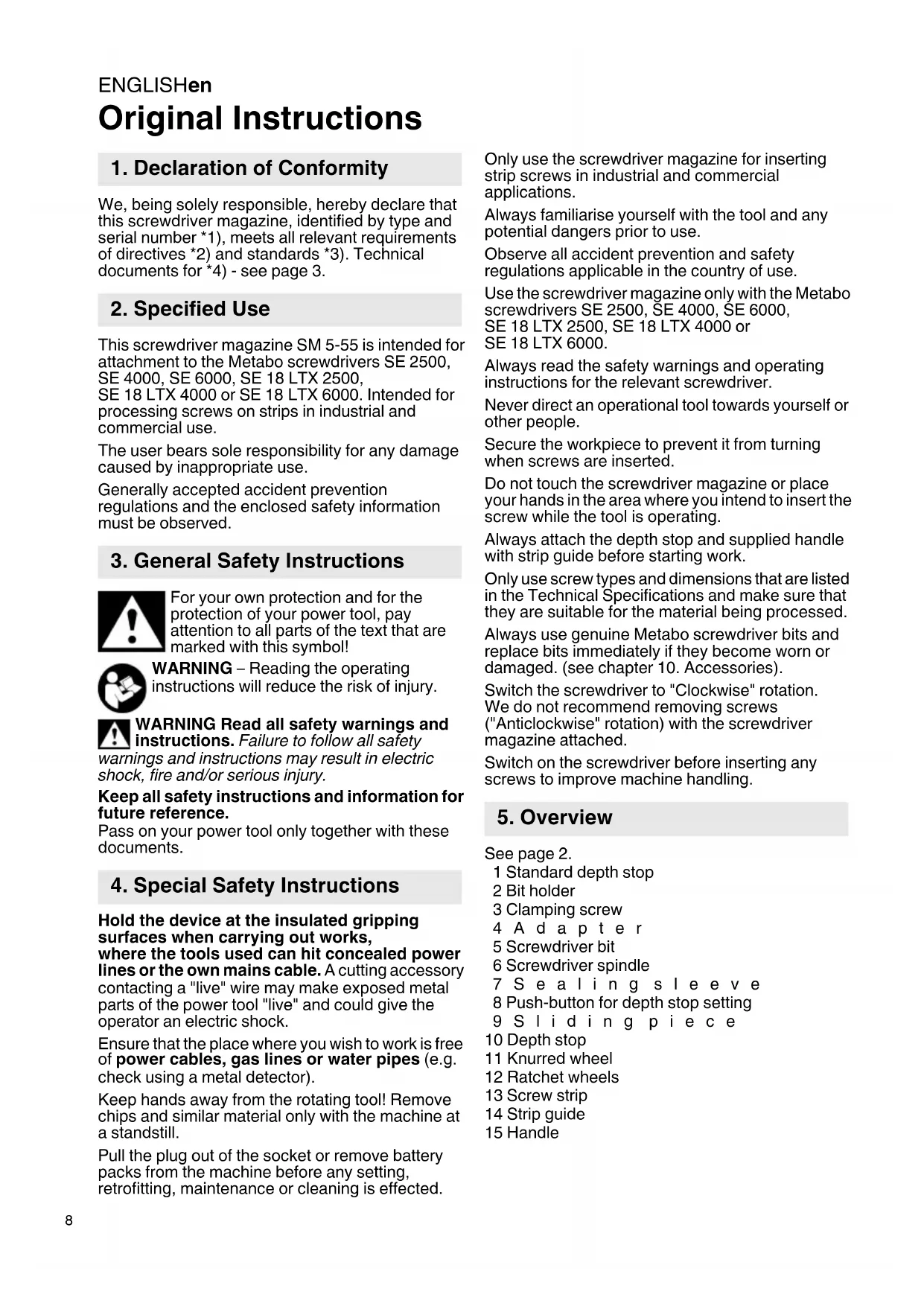
Three screws aligned horizontally with double-headed arrows indicating alignment (no text or symbols)Original Instructions
1. Declaration of Conformity
We, being solely responsible, hereby declare that this screwdriver magazine, identified by type and serial number *1), meets all relevant requirements of directives *2) and standards *3). Technical documents for *4) - see page 3.
2. Specified Use
This screwdriver magazine SM 5-55 is intended for attachment to the Metabo screwdrivers SE 2500, SE 4000, SE 6000, SE 18 LTX 2500, SE 18 LTX 4000 or SE 18 LTX 6000. Intended for processing screws on strips in industrial and commercial use.
The user bears sole responsibility for any damage caused by inappropriate use.
Generally accepted accident prevention regulations and the enclosed safety information must be observed.
3. General Safety Instructions

For your own protection and for the protection of your power tool, pay attention to all parts of the text that are marked with this symbol!

WARNING – Reading the operating instructions will reduce the risk of injury.

WARNING Read all safety warnings and instructions. Failure to follow all safety
warnings and instructions may result in electric shock, fire and/or serious injury.
Keep all safety instructions and information for future reference.
Pass on your power tool only together with these documents.
4. Special Safety Instructions
Hold the device at the insulated gripping surfaces when carrying out works, where the tools used can hit concealed power lines or the own mains cable. A cutting accessory contacting a "live" wire may make exposed metal parts of the power tool "live" and could give the operator an electric shock.
Ensure that the place where you wish to work is free of power cables, gas lines or water pipes (e.g. check using a metal detector).
Keep hands away from the rotating tool! Remove chips and similar material only with the machine at a standstill.
Pull the plug out of the socket or remove battery packs from the machine before any setting, retrofitting, maintenance or cleaning is effected.
Only use the screwdriver magazine for inserting strip screws in industrial and commercial applications.
Always familiarise yourself with the tool and any potential dangers prior to use.
Observe all accident prevention and safety regulations applicable in the country of use.
Use the screwdriver magazine only with the Metabo screwdrivers SE 2500, SE 4000, SE 6000, SE 18 LTX 2500, SE 18 LTX 4000 or SE 18 LTX 6000.
Always read the safety warnings and operating instructions for the relevant screwdriver.
Never direct an operational tool towards yourself or other people.
Secure the workpiece to prevent it from turning when screws are inserted.
Do not touch the screwdriver magazine or place your hands in the area where you intend to insert the screw while the tool is operating.
Always attach the depth stop and supplied handle with strip guide before starting work.
Only use screw types and dimensions that are listed in the Technical Specifications and make sure that they are suitable for the material being processed.
Always use genuine Metabo screwdriver bits and replace bits immediately if they become worn or damaged. (see chapter 10. Accessories).
Switch the screwdriver to "Clockwise" rotation. We do not recommend removing screws ("Anticlockwise" rotation) with the screwdriver magazine attached.
Switch on the screwdriver before inserting any screws to improve machine handling.
5. Overview
See page 2.
1 Standard depth stop
2 Bit holder
3 Clamping screw
4 A d a p t e r
5 Screwdriver bit
6 Screwdriver spindle
7 Se a l i n g s l e e v e
8 Push-button for depth stop setting
9 Sliding piece
10 Depth stop
11 Knurred wheel
12 Ratchet wheels
13 Screw strip
14 Strip guide
15 Handle
6. Commissioning 7. Use
6.1 Attaching the magazine to the screwdriver
- Remove the standard depth stop (1) and bit holder (2) of the screwdriver (follow the screwdriver operating instructions).
Note:
The bit holder (2) may be removed from the screwdriver spindle if the sealing sleeve (7) is pulled back.
- Insert the screwdriver bit (5) into the screwdriver spindle (6) of the screwdriver (follow the screwdriver operating instructions).
- Put the screwdriver magazine with the adapter (4) over the screwdriver bit (5) onto the screwdriver. Ensure that the anti-twist mechanism of both sides interlink without force.
Remark:
The adapter (4) can be attached to the screwdriver in 8 positions (each rotated in 45° increments). After loosening the clamping screw (3), the screwdriver magazine can be aligned parallel to the screwdriver. Tighten the clamping screw (3) again.
6.2 Adjusting the depth stop (10)
The numbers on the depth stop (10) correspond to the screw lengths (mm) that the tool is capable of inserting.

The depth stop (10) must be adapted to the length of the screws being inserted.
- Press the push-button (8) and keep pressed, set the depth stop (10) to the screw length in accordance with the screw length used by moving the depth stop (10). The screw length can be read off on the scale.
- Subsequently, the push-button must engage: Release the push-button and move the depth stop until the push-button engages.
6.3 Presetting the screw depth
The screw depth must be adjusted every time the screw size changes and the position of the depth stop (10) is modified.
- Push in the depth stop (10) up to the stop and hold in this position.
- The tip of the screwdriver bit (5) should protrude approx. 3 mm beyond the depth stop (10).
- If required, adjust the screw depth by turning the knurled wheel (11):
- If the screwdriver bit is to protrude more: Turn the knurled wheel (11) downwards.
- If the screwdriver is to protrude less: Turn the knurled wheel (11) upwards.
Fine adjustment is performed after the tool is tested. See section 7.3.
The magazine screw attachment is now ready for operation.
7.1 Inserting / Removing a screw strip (13)
Check whether the screw heads are resting on the plastic strip otherwise the strip guide (14) may become damaged and no longer function correctly.
The screw strip (13) can be inserted from either side.
- Push the screw strip (13) from below through the belt guide (14).
- Then guide the holes on the strip over the tips of the teeth on the ratchet wheels (12), until the screw is located in the position in front of the insertion position. The screwdriver bit (5) picks up this screw when the depth stop (10) is pushed down. For this reason, do not push the screw strip (13) in too far to avoid wasting any screws.
To remove the screw strip (13), pull it forwards through the tool. Do not pull back the screw strip (13). This may cause serious damage.
7.2 Machine use
We recommend:
- Setting the screwdriver to clockwise rotation.
- Setting the screwdriver to run continuously.
- Hold the screwdriver with one hand. Hold the handle (15) with the other hand if necessary.
- Hold the tool at right angles to the work surface. The screw will not be inserted far enough if the tool is held at an angle that deviates from 90° even slightly.
- Rest the depth stop (10) on the screwdriver magazine against the workpiece and apply pressure.
- The screw moves to insertion position and is screwed into the workpiece.
- If the coupling on the screwdriver audibly disengages, remove the magazine screw attachment from the workpiece.
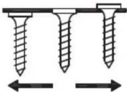
7.3 Precision screw depth adjustment
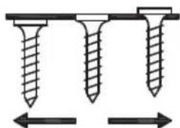
natural_image
Diagram showing three different screw configurations with directional arrows indicating measurement or alignment (no text or symbols)The screw depth (or countersink depth) is adjusted by turning the knurled wheel (11).
- Insert a screw to test the tool settings.
- If required, fine-tune the screw depth by turning the knurled wheel (11):
- If the screw head is to protrude more: Turn the knurled wheel upwards.
- If the screw head is to protrude less: Turn the knurled wheel downwards.
7.4 Changing the screwdriver bit (5)
Always use genuine Metabo screwdriver bits (see chapter 10. Accessories).
ENGLISHen
If the screwdriver bit is worn/damaged or a different fastening system is used (Philips, Pozidrive, Torx or Square Drive), the screwdriver bit must be changed.
- Detach the screwdriver magazine with adapter (4) from the screwdriver (do not slacken the clamping screw (3)).
- Remove the screwdriver bit (5) (read the screwdriver operating instructions).
Note:
The bit holder (5) may be removed from the screwdriver spindle if the sealing sleeve (7) is pulled back.
- Insert a new screwdriver bit (5) (read the screwdriver operating instructions)
- Re-attach the screwdriver magazine with the adapter (4) at the screwdriver (see chapter 6.1).
8. Troubleshooting
Problems:
- Countersink depth: see point b), d), e), h)
- Seized screws: see point b)
- Missing screws: see points c), g)
- Screws do not move: see points a), d)
- General: see points a) to i)
Troubleshooting:
a Always set the screwdriver to CLOCKWISE ROTATION (FORWARDS).
b Make sure that the depth stop (10) is adapted to the length of the screws used.
c The screwdriver bit (5) must be the correct length. Always use genuine Metabo screwdriver bits (see chapter 10. Accessories).
d If you are working with Philips screws, make sure you use a Philips screwdriver bit. If you are working with Pozidrive screws, make sure you use a Pozidrive screwdriver bit.
e If you are unable to insert screws to the required depth, adjust the knurled wheel (11) until the screw depth is correct.
f Make sure that the screwdriver bit is attached correctly (read the screwdriver Operating Instructions).
g If you notice that the screw strip (13) is not being fed in correctly (screws do not appear or are missing), make sure that you push back the depth stop (10) all the way and then move a sufficient distance from the workpiece to allow the depth stop to return to its original position. The screwdriver magazine is loaded when pushed down, therefore it might be filled wrongly if not the entire stroke has been effected. Do not set the tool down on the depth stop (10) as this may feed in screws unintentionally.
h Hold the tool at right angles to the work surface. The screw will not be inserted deep enough if the tool is held at an angle that deviates from 90^ even slightly.
9. Maintenance
Recommended maintenance intervals:
Daily:
Check the screwdriver magazine for damage and clean using compressed air (wear protective goggles).
Weekly:
- Remove heavy dirt deposits manually without using aggressive cleaning agent.
- Do no lubricate individual components.
10. Accessories
Use only genuine Metabo accessories.
Use only accessories which fulfil the requirements and specifications listed in these operating instructions.
Screwdriver tools / screwdriver bits:
(length: 180 mm)

PH (Philips) no x 180 mm (6.31582)
See www.metabo.com or the catalogue for a complete range of accessories.
11. Repairs
Repairs to devices must be carried out by qualified specialists only!
If you have Metabo power tools that require repairs, please contact your Metabo service centre. See www.metabo.com for addresses.
You can download a list of spare parts from www.metabo.com.
12. Environmental Protection
Observe national regulations on environmentally compatible disposal and on the recycling of disused machines, packaging and accessories.
13. Technical Specifications
Changes due to technological progress reserved.
Weight :
0.6 kg
Compatible screw types, in screw strip:
Plasterboard screws
Chipboard screws
Steel roofing screws
Timber construction screws
Fibreboard screws
Compatible screw dimensions:
Length(mm)=20/25/30/35/40/45/50/55
Shank diameter (mm)= max. 5 mm
Head diameter (mm)= max. 9.5 mm
Screwdriver bits for screw drive:
PH (Philips) no. 2 x 180 mm
The technical specifications quoted are subject to tolerances (in compliance with the relevant valid standards).
Notice originale
natural_image
Diagram showing three different screw configurations with directional arrows indicating alignment (no text or labels)natural_image
Diagram showing three different screw configurations with directional arrows indicating alignment (no text or labels)natural_image
Diagram showing three different screw configurations with directional arrows indicating alignment (no text or labels)natural_image
Diagram showing three different screw configurations aligned horizontally with bidirectional arrows indicating alignment (no text or symbols)natural_image
Diagram showing three different screw configurations aligned horizontally with bidirectional arrows indicating alignment (no text or symbols)natural_image
Diagram showing three different screw configurations with directional arrows indicating alignment (no text or symbols)natural_image
Diagram showing three different screw positions aligned horizontally with directional arrows indicating alignment (no text or symbols)7.3 Fininnstille innskruingsdybden
natural_image
Diagram showing three different screw configurations with bidirectional arrows indicating alignment (no text or symbols)natural_image
Diagram showing three different screw configurations with directional arrows indicating alignment (no text or symbols)Iskruningsdybden (eller skruedybden) indstilles ved at dreje på føringshjulet (11).
natural_image
Diagram showing three different screw configurations aligned horizontally with directional arrows indicating alignment (no text or symbols)POLSKIpl
natural_image
Diagram showing three different screw configurations aligned horizontally with directional arrows indicating alignment (no text or symbols)natural_image
Diagram of three screws aligned horizontally with bidirectional arrows indicating alignment (no text or symbols)natural_image
Diagram showing three different screw configurations aligned horizontally with bidirectional arrows indicating alignment (no text or symbols)


- Original Instructions
- Declaration of Conformity
- Specified Use
- General Safety Instructions
- Special Safety Instructions
- Overview
- Commissioning 7. Use
- Attaching the magazine to the screwdriver
- Adjusting the depth stop (10)
- Presetting the screw depth
- Inserting / Removing a screw strip (13)
- Machine use
- Precision screw depth adjustment
- Changing the screwdriver bit (5)
- ENGLISHen
- Troubleshooting
- Problems:
- Troubleshooting:
- Maintenance
- Daily:
- Weekly:
- Accessories
- Repairs
- Environmental Protection
- Technical Specifications
- Notice originale
- Fininnstille innskruingsdybden
- POLSKIpl
Brand : METABO
Model : SM 555
Category : Screwdriver