
KLL 220 - Laser pointer METABO - Free user manual and instructions
Find the device manual for free KLL 220 METABO in PDF.
| Product type | Cross-line and plumb point laser |
| Brand | Metabo |
| Model | KLL 220 |
| Power supply | 3 AA LR6 alkaline batteries (1.5 V) |
| Battery life | Approximately 20 hours (with alkaline batteries) |
| Laser type | Red diode, class 2, wavelength 635 nm, power < 1 mW |
| Self-leveling range | ± 4.5° |
| Horizontal leveling accuracy (line) | ± 0.3 mm/m |
| Line inclination accuracy | ± 0.2 mm/m |
| Upward beam accuracy | ± 0.3 mm/m |
| Downward beam accuracy | ± 0.4 mm/m |
| Operating temperature range | -10 °C to +50 °C |
| Storage temperature range | -20 °C to +60 °C |
| Tripod thread | 1/4" |
| Included accessories | Wall mount, magnets, telescopic stand, shock protection |
| Main functions | Horizontal and vertical laser lines, top and bottom plumb points, pulsed mode for receiver |
| Operating modes | Self-leveling and manual mode (without leveling) |
| Maintenance and cleaning | Clean with a soft, dry cloth; store in the protective case |
| Safety | Class 2 laser: do not look directly into the beam; follow safety instructions |
| Spare parts and repairability | Standard batteries; for repair, contact Metabo representative |
Frequently Asked Questions - KLL 220 METABO
User questions about KLL 220 METABO
0 question about this device. Answer the ones you know or ask your own.
Ask a new question about this device
Download the instructions for your Laser pointer in PDF format for free! Find your manual KLL 220 - METABO and take your electronic device back in hand. On this page are published all the documents necessary for the use of your device. KLL 220 by METABO.
USER MANUAL KLL 220 METABO
Operating instructions
The Metabo KLL 2-20 is an easy to use crossed line and plumb line laser. It is self-leveling in the range ± 4.5^ and enables levels to be determined quickly and accurately. The vertically and horizontally projected laser lines provide exact alignment / working .
The pulsed laser-line enables working over larger distances using a special laser-line-receiver.
Read the User Manual along with the illustrated portion. Follow the general instructions on the handling, care and maintenance of the instrument.
Observe the safety instructions on laser beams.

Main components
(1a) On/off button
(1b) ON / OFF switch (for protecting during transport)
(2) LEDs for displaying
(2a) Operating mode ON or READY
(2b) Battery voltag
(3) Exit aperture for the horizontal and vertical laser lines
(4) Plumb line laser outlet
(5) Foot - extendable
(6) Release lever
(7) Battery compartment cover
(8) Protective cover
(9) 1 / 4 "threaded connector for tripod
(10) Magnets
(11) Wall bracket

Before initial start-up :
The warning notice in your language must be clearly affixed on the laser instrument at the position indicated. The appropriate stickers are enclosed.
This sticker with the warning notice written in the usual language must be affixed here in place of the English text!
LA SER RA DI ATIONDO NOT ST ARE IN TO BE AMLA SER CL AS S 2
Batteries must be inserted changing batteries
Main applications: Operating modes
The KLL 2-20 can be used in 2 operating modes:
- as a self-levelling line laser 2. as a laser instrument for marking
- plumb line laser applications without the levelling function
Operating mode with self-levelling
A laser line can be selected in this mode.
Commissioning
The instrument is switched on with the on/off switch (1b). Horizontal and vertical laser lines and the plumb line points appear after switching on. The laser will automatically level itself.
Setting the type of line:
The vertical and horizontal laser lines with the plumb line point and the cross laser line can be set after each other by pressing the selector switch (1a). The laser will flash if the inclination is too great!
laser beam flashing-> The unit is inclined too much
- is outside the self-levelling range
- the laser cannot level itself automatically
Operating mode without levelling function:
The on/off switch (1b) is switched off. In this mode the KLL 2-20 is only switched on or off with the selector switch (1a).
Plumb line function mode
The foot can be extended in order to improve the visibility of the lower plumb line point. The KLL 2-20 is positioned and switched on ( switch 1b ). The laser down beam is aligned as required to the object or a mark. Mark the position of the up laser beam on the ceiling. The laser lines are always switched on at the same time as the plumb line laser points. Always ensure that the centre of the laser line is marked !
Checking the calibration
KLL 2-20 crossed line and plumb line laser is designed for use on the construction sites and left our factory perfectly adjusted. As with any precision instrument, however, its calibration must be regularly checked. The unit should be checked before starting any new tasks, particularly when the unit has been exposed to strong vibrations.

Horizontal checking
1. Horizontal checking - Line level
Two parallel wall surfaces at least 5m / 16^5^ apart are required for the horizontal check.

-
Place the KLL 2-20 on a smooth surface or on a tripod at a distance of 50mm to 75mm in front of wall A and with the front side pointing towards the wall
-
Switch the unit on (1b).
-
Mark the position of the visible laser line cross on the wall A (point 1).

-
Turn the complete unit 180^ without altering the height of the laser.
-
Mark the position of the visible laser line cross on the wall B (point 2).

-
Now move the unit directly in front of wall B.
-
Set the unit's height so that the laser dot's height matches that of point 2.

- Without changing the height of the laser, rotate it 180^ to place the beam near the mark on the first wall (step 3 / point 1).
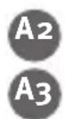
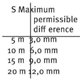
Measure the vertical distance between point 1 and point 3. The difference must not be greater than:

2. Horizontal checking - inclination of the laser line
Check the laser line for inclination and perfectly straight projection


- Mark three points (1, 2 and 3) on the floor at a distance of 5m / 16'5'' from each other; the points must be in a perfectly straight line.
- Position the laser at distance S = 5 m / 16^5^ from the line and exactly in front of the middle point you marked = position X
- Switch the unit on.
- Measure the height of the laser line at the points. Measurements X1 - X3
- Reposition the instrument.
- Position the laser at distance S = 5 m / 16^5^ from the line and exactly in front of the middle point you marked = position Y
- Measure the height of the laser line at the points. Measurements Y1-Y3
$$ \Delta 1 = X _ {1} - Y _ {1} \quad \Delta 2 = X _ {2} - Y _ {2} \quad \Delta 3 = X _ {3} - Y _ {3} $$
The following applies for the differences :
$$ \begin{array}{l} \Delta \mathrm {g e s} 1 = \Delta 1 \cdot \Delta 2 \leq \pm 2 \mathrm {m m} 5 / 6 4 ^ {\prime \prime} \ \Delta \mathrm {g e s} 2 = \Delta 3 - \Delta 2 < \pm 2 \mathrm {m m} 5 / 6 4 \ \end{array} $$
When calculating, always take note of the preceding prefix x!
Vertical check
You must create a reference to perform this test. Fasten a plumbline near to the wall. The laser unit should now be set up in front of this reference mark (distance Y) and the vertical laser line compared with it.
The discrepancy between the centre of the laser line and the reference mark should be no greater than 1mm (3/64") over a length of 2 m (8 ft).
Checking plumblining
- Switch the unit on
- Place the laser so that its down beam is over a reference mark on the floor.
- Locate the position of the up beam on the ceiling and make a mark.
- Rotate the laser 180^ and realign the down beam over the reference mark on the floor.
- Locate the position of the up beam on the ceiling and make a mark.
- Measure the difference D between the two marks on the ceiling, which will be twice the actual error. The difference may not be greater than: 3 ~mm in 5 ~m (1/8" in 16'5").
Replacing the batteries
Slide the battery cover (4) in the direction of the arrow and insert new batteries in accordance with the symbols in the battery compartment.
Suitable batteries can also be used.
Technical data
Laser type: Red diode laser, pulsed line-laser,
W a V e
Output: < 1 mW, Laser Class 2 to IEC 60825-1:2007
This product compl. with the appl. requ. of 21CFR, parts 1040.10 and 1040.11.
Self-levelling range*: ca. ± 4,5°
Levelling accuracy :
laser line horizontal*: L1 = ± 0,3 mm/m middle of the laser line
L_1 = ± 3 / 16 over 50ft
inclination of the laser line: L2 = ± 0.2 mm/m laser line
L2 = ± 1/8" over 5oft
Up Beam Accuracy*: L3 = ± 0,3 mm/m ± 3/16" over 50 ft
Down Beam Accuracy: L_4 = ± 0,4mm / m± 1 / 4^ over 50 ft
Batteries:: 3 × 1,5 ~V cells Alkaline, Size AA, LR6 LR6
Operating life: Approx. 20 hours (Alkaline)
Operating temperature range : -10 °C to +50 °C / 14°F to +122°F
Storage temperature range: -20°C to +60°C / -4°F to +140°F
Subject to technical modifications.
- When operated within specified temperature range
en
Metabo Measuring Tools requiring Service
Contact your local Metabo representative if you have Metabo measurement devices requiring service. See www.metabo.com for addresses.
Mode d'emploi
L2 = ±1/8" sobre 5oft
| S alor | máximo admitido |
| 5 m | 3,0 mm |
| 10 m | 6,0 mm |
| 15 m | 9,0 mm |
| 20 m | 12,0 mm |
| S | m a x tillåtet ∀rde |
| 5 m | 3,0 mm |
| 10 m | 6,0 mm |
| 15 m | 9,0 mm |
| 20 m | 12,0 mm |
G1 2. Horisontalkkontroll - Laserlinjens lutning
| S maks. tillatt verdi |
| 5 m 3,0 mm |
| 10 m 6,0 mm |
| 15 m 9,0 mm |
| 20 m 12,0 mm |
G1 2. Horisontalkkontroll - Laserlinjens helling
KoHTpoJIb KaJIn6pOBKn
Ja3epHbI np6op c nepecekaUoMmncJinHnmaN i fynKcnei OTBeca KLL 2-20 cKOHCTpynpOBaH dIra pa6Otbl Ha cTpoINLOuaAdkax N 6bl IOTnpabLnE h cHaWeero 3aBODa B 6e3ynpueHNO HAcTpoEHHom COCTOAHNN. Nepei NoCTABKO np6oPa C HauWero 3aBODa 6bla BbINOJIHeHa erO TsaTeJIbHa JOCHTPOBka. Ho KaK y BCex Ppeu3IOHHbIX INCTpymeHTOB Heo6XoDmO peYIapHO KOHTPOINPOBaTb COCTOAHne KaIb6PobKn. KaJdbI pa3 nepei NaJalom pa6Otbl, B Oco6eHNocTN, ecnn np6Op nOdBepraIcraCInhblIM COTpIceHnA M, Heo6XoDmO BblONHHTb KOHTPOlb.
TOpH3OHTaJIbHbI KOHTpOJIb
- TOpH3OHTaJIbHbI KOnTpoJIb -JIInHeiHbI yPoBeHb
JIa BBInOJIHeHnI ROpH3OHTaJIbHO KOHTpOJI Heo6XOnMo B3rTb 2
IapaJIeJIbHbIe IOBepXHOCTn Ha CTeHe Ha paCCTOHHaK MHNmym 5 M.
- YCTaHOBtB KLL 2-20 Ha paCCToHnB pa3Mepe OT 50 MM do 75 MM OT CTeHbI A Ha rOpH3OHTaJIbHOJ IOBepXHOCTN HIN Ha IITaTnB C IpeEHNCTOPOH B HAIIpaBJIeHne CTeHbI.
- Bкл�чть npнбop (1b).
- BbIIOJIHNITb MapKINPOBky BnIMMOJ KpeCToo6pa3HOJ TOUKN Ja3epHbIX JInHH Na CTeHe A (TOUka 1).
- Повернту вescь Лазэрьп рибор пиблнerteьно на 180^ -прг 3ТOM He ИЗмehтв ВсICOTу Лазэр.
- 发射机
- 转换器
- 滤层
- 管路
- 排气管
- 阀体
- 压力调节器
- 调节器
- 调节阀
- 调节阀
- 调节阀
- 调节阀
- 调节阀
- 调节阀
- 调节阀
- 调节阀
- 调节阀
- 调节阀
- 调节阀
- 调节阀
- 调节阀
- 调节阀
-
调节阀
- 调节阀
- 调节阀
- 调节阀
- 调节阀
- 调节阀
- 调节阀
- 调节阀
- 调节阀
- 调节阀
- 调节阀
- 调节阀
- 调节阀
- 调节阀
- 调节阀
- 电控机
- 电控机
- 电控机
- 电控机
- 电控机
- 电控机
- 电控机
- 电控机
- 电控机
- 电控机
- 电控机
- 电控机
- 电控机
- 电控机
- 电控机
- 电控机
- 电控机
- 电磁波
- BbIIOJIHnTb MapKnpoBky BnIhMoN KpeCToo6pa3HOJ TOUKN Ja3epHBIX JInHn Ha cTeHe B (ToUka 2).
- YctaHOBtB Ia3epHbI IIpH6Op HeIOcpeCTBeHHo IpeD cTeHO B
- BbIIOJIHnITb IepemeIeHne Ipi6opa IO BBICOTe IO Tex Iop, NOKa BbICOTa Ja3epHOJ TOUKN He 6yJeT COBnaIaTB C ToUKO2.
- ПовернITE Лазэрьй пибор на 180°, He Измени пи NTOM BBICOTы, с цью позионровая Лазэрно Луча рядом с первов МарКнировков (Операця 3 / пункт 1).
I3MepeBTe BepTKKaJIbHoe paCCTOaHne MeKdy TOnkAmn 1 n 3. Ppr n 3TOM pa3HHa He dOJIxHa 6bITb 60JIbIe yem:
S MaKcHMaJIbHo IOIYCTHMoe 3HaueHHe
5m3,0mm
10m6,0mm
15 m9,0 mm
20m12,0mm
- TOpH3OHTaJIbHbI KOnTpoJIb - HaKIOH Ia3epHOJ IINHH
KoHTpoJIb Ia3epHOJ IINHII IIOI HaKIOHOM I a6COJIOTHO TOUHaI IPOeKIIJa.
- BbIIOJIHnTe MapKnpoBky Tpex ToyeK Ha nOly 1-3, KaJdA Ha paCCToRHHn B pa3Mepe 5 M, KOTOpBie IOJIKHbI HaxOJNTbcr ToUHO Ha OJHO JINHHN.
- YcTaHOBHTe Ja3epHbI IprH6Op Ha paCCTOaHHN S = 5 MM OT JInHH ToUHO IpeIeHTpaJIbHOm MapKnpoBKOJ = IIO3nua X
- BkIIOuHTb npH6Op .
- BbIIOJIHnTe Ha 06O3HaueHHbIX TOUkax H3MepeHne BBICOTbI Ja3epHOJ JINHHN. I3MePHTeJIbHbIe 3HaueHnX1 - X3
- IpeceTaBHTb npH6Op.
- YctaHOBHTe Ja3epHbI Ipn6Op Ha paCCTOAHN H S = 5 MM OT JHHHn TOUHO IpeE IeHTpaJIbHOJ MapKHPoBKOJ = IIO3HnJY
- BbIOJIHnTe Ha 06O3HaueHHbIX TOUkax H3MepeHne BBICOTbI Ja3epHOJ JINHHN. N3MeprteJIbHbIe 3NaueHnY1 - Y3.
$$ \Delta 1 = \mathrm {X} 1 - \mathrm {Y} 1 \quad \Delta 2 = \mathrm {X} 2 - \mathrm {Y} 2 \quad \Delta 3 = \mathrm {X} 3 - \mathrm {Y} 3 $$
Ipa3HnIeHCTBHTeJIbHbIM ABJETcYCIOBHe:
ges1 = 1 - 2 < ± 2mm
ges2 = 3 - 2 < ± 2mm
IIpn BbIIOJIHeHH N BbyHCJIeHH 06paTHTe BHHMaHHe Ha 3HaKN!
ru
BepTKaJIbHbI KOHTpoJIb
Дя BBIOJIHHeHЯ 3TOFO KOHTPOJIA Heo6XODHMO IOIROTOBHTb 6a3OBYHO TOUYK. 3aKpeIInTe,HaIIpIMep,OTBeC pIOM CO CTeHOn. Ja3epHbI Ipi6Op TeIepb yCTaHaBJIHBaETcI PePeI 3TOI 6a3OBOI MapKnIpOBKOI (pacCTOJHHe y).
C Hei cpaBHHBaETcBePTHKaJIbHaJ Ia3epHaJ IHHNJa. Ha IINHe B pa3Mepe
2 M OTKJIIOHeHHe ΚeHTpa JINHH JINHeHOrO Ja3epa IIO OTHOIIeHnHO K 6a3OBoT OUKe He IOJIJKHO IIpeBbIiTaTb 1 MM.
KoHTpoJIb IIO OTBecy
- BkJIIOuHTb npH6Op .
- BbIIOJIHnTe IIO3NIOHnPOBaHnE Ja3epHOrO IIpH6opa TaKIM 06pa3OM, YTO6bl BePTHKaJIbHbI JIA3epHbI JyU 6blI HApPaBJeH BHN3 Ha MapKnPObKY Ha NOJy
- ПониБeДиTe МарКИрOBКу пОЗиСилaЗерHOrO Луча ВВерх Ha ПОТOLke.
- ПовернITE Лаэрьй пибор Ha 180°, И сюва направte Вертукалыньий Лаэрьй Луч Винз Ha Маркуровky Ha ПОЛУ.
5.ПронЗБeДиTe МарКнрOBКу ПОзИн Ла3epHOrO Луч ВВерх Ha NOTOLke. - Измерб Te pa3Hиу D MeJy DByMЯ OTMeTKaMH Ha NOTOLke, KOTopa BДBa pa3a 6OJIbIe DeHCTBHTeJIbHOI IORpeSHHOCTN. Прн 3TOM IIprn 5 M pa3Hиц He DoJIxHa IIpeBbIiTaTb 3 MM!
3aMeHa 6aTapeH
OTKpoIte KpbIIuKy KapMaHa 6aTapei (4) IIO HApPaBJIeHnIO CTpeJKN.
BcTaBbTe HOBbIe 6aTapeKn COJIaCHO CHMBOJy. MoXHO HcIOJIb3OBAbTaKKe COOTBeTCTByIOJIne aKKymyJIrTOpbl.
TexHnueckne daHHbIe
TnI Ja3epa: IIOHbI JIa3ep KpaCHoro UBeTa, IINHeHbI Ja3ep B IIyIbCnpyUoIeM peKHMe DIIHa BOJIH 635 nm
BbIXoHnHa MoHocTb: <1 mW, KJIaCC Ja3epa 2 coIaCHO H O
p M e
Дианэзн самониьлрованг*: np6n3nteьho ± 4,5° ToHOCt b HbIINpOBaHn*:
JIa3epHnaJIHHn, rOpH3oHTaJIbHo*: L1 = ± 0,3 mm/m ΒeHTpJa3epHOJInHHn
HaKIOH Ia3epHoJIHHN : L2 = ± 0,2 mm/m JIa3epHaJIHHN BepTKaJIbHbI JIyU BBepx: L3 = ± 0,3 mm/m BepTKaJIbHbI JIyU BHN3: L4 = ± 0,4 mm/m
Батуарен: 3x1,5ВячЕйКМMHBOH,ицIoUHьIE, ra6apNTbI AA, LR6
ДЛNTeJIbHOCtB 3KcIIpyaTauHH: np6JIu3NtTeJbHo 20 yacOB (IeIoUHbIe)
Bzemi hymirsklet: -10°C, Ωo +50°C
Дианэон TeIMepeatypbIXpaHeHЯ: -20°C ,do +60°C
MbIOCTABJIaEM3aCO6oIIPABOHaTexHHueCKHeH3MeHeHHN.
*PpH pa6Ote B IpeJax yka3aHHoro DnHa30Ha TeMIIepaTpybI
Tpe6yUoIe TexO6cLyJXuBaHnI N3MePnteJIbHbIe HNCTpyMeHTbI Metabo
TapaHTnHbI CpOK:1rOaTbIpOdaJN CpOK cnyK6bl HcTpymeHa:5JeT C DaTbI N3rOToBHeHna
CE
Metabowerke GmbH
Metabo-Allee 1
D-72622 Nuertingen
Germany
www.metabo.com
- Operating instructions
- Main components
- Before initial start-up :
- Main applications: Operating modes
- Operating mode with self-levelling
- Commissioning
- Setting the type of line:
- Operating mode without levelling function:
- Plumb line function mode
- Checking the calibration
- Horizontal checking
- Horizontal checking - Line level
- Horizontal checking - inclination of the laser line
- Vertical check
- Checking plumblining
- Replacing the batteries
- Technical data
- en
- Metabo Measuring Tools requiring Service
- Mode d'emploi
- G1 2. Horisontalkkontroll - Laserlinjens lutning
- KoHTpoJIb KaJIn6pOBKn
- TOpH3OHTaJIbHbI KOHTpOJIb
- 调节阀
- ru
- BepTKaJIbHbI KOHTpoJIb
- KoHTpoJIb IIO OTBecy
- 3aMeHa 6aTapeH
- TexHnueckne daHHbIe
- Tpe6yUoIe TexO6cLyJXuBaHnI N3MePnteJIbHbIe HNCTpyMeHTbI Metabo
- CE
Brand : METABO
Model : KLL 220
Category : Laser pointer