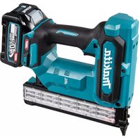
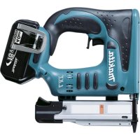
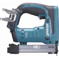
DBN500 - Electric stapler MAKITA - Free user manual and instructions
Find the device manual for free DBN500 MAKITA in PDF.

| Technical specifications | Pneumatic stapler, compatible with 18GA type staples, capacity of 100 staples, operating pressure from 5 to 7 bars. |
|---|---|
| Usage | Ideal for finishing work, wall covering installation, and furniture assembly. |
| Maintenance and repair | Regularly check the oil level, clean the air filter, and replace worn seals to ensure optimal operation. |
| Safety | Wear safety glasses, do not point the tool towards yourself or others, and follow the safety instructions provided in the user manual. |
| General information | Lightweight for easy handling, ergonomic design, and 1-year manufacturer warranty. |
Frequently Asked Questions - DBN500 MAKITA
User questions about DBN500 MAKITA
0 question about this device. Answer the ones you know or ask your own.
Ask a new question about this device
Download the instructions for your Electric stapler in PDF format for free! Find your manual DBN500 - MAKITA and take your electronic device back in hand. On this page are published all the documents necessary for the use of your device. DBN500 by MAKITA.
USER MANUAL DBN500 MAKITA
GB Cordless Brad Nailer Instruction manual
natural_image
Technical line drawing of a mechanical assembly (no text or symbols visible)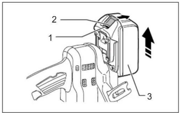
text_image
Technical diagram of a device with labeled parts and directional arrows indicating movement or assembly.1 014581 2 014584
text_image
4
text_image
Diagram showing a device connected to a labeled component with parts 6 and 7, likely illustrating a connector or wiring assembly.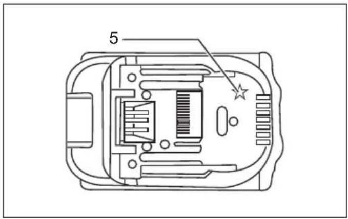
text_image
53 012128 4 015659
text_image
11 12 13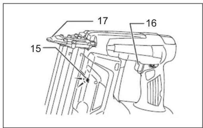
text_image
15 16 17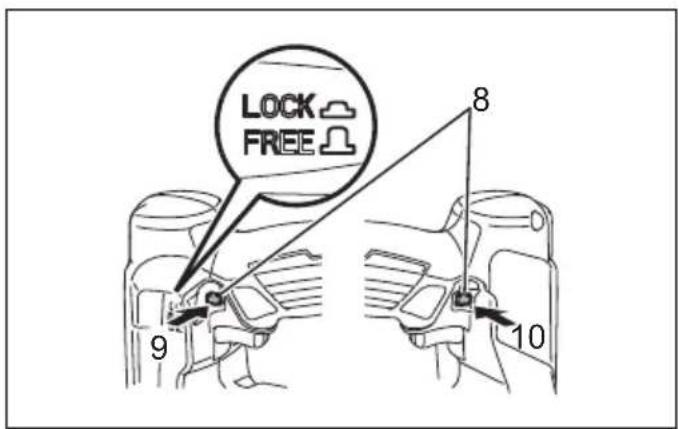
text_image
LOCK FREE 8 9 105 014582 6 014618
text_image
A B 147 014601 8 014600
text_image
18 20 21 199 014585 10 014592
text_image
20 19 22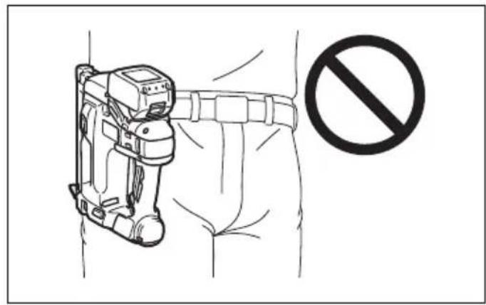
text_image
Safety warning illustration showing a medical device with a no-smoking symbol nearby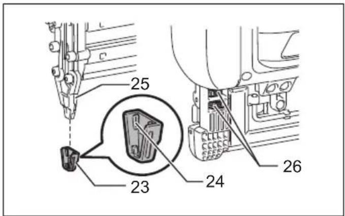
text_image
25 23 24 2611 014586 12 014587
text_image
30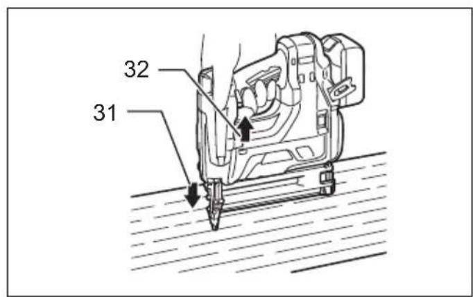
text_image
32 31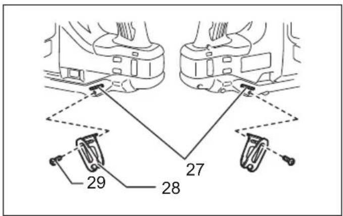
text_image
27 28 2913 014588 14 014589
text_image
32 3115 014619 16 014620
text_image
33 35 34 3617 014591 18 004310
natural_image
Two hands holding a cube with the number 37 on top (no text or symbols beyond the number)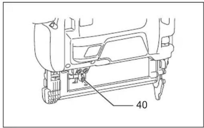
text_image
40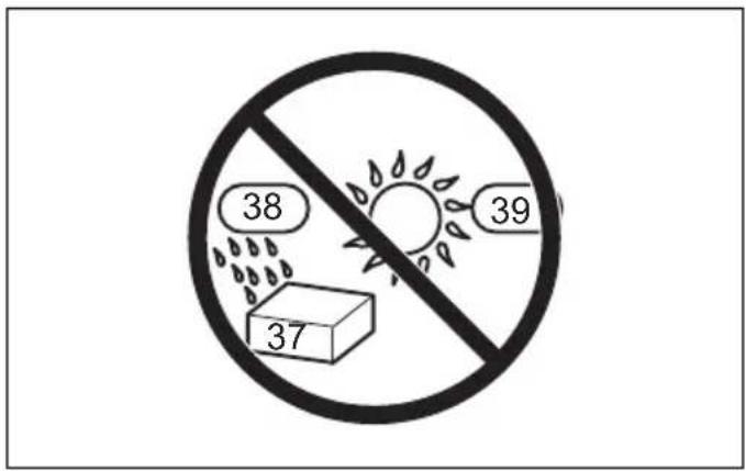
text_image
38 37 3919 004311 20 014720
text_image
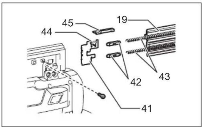
44 45 19 42 43 4121 014721
ENGLISH (Original instructions)
Explanation of general view
| 1. Red indicator | 17. Driver guide (contact element) | 32. Pull the trigger. |
| 2. Button | 18. Lock lever | 33. Hex bolt A |
| 3. Battery cartridge | 19. Slide door | 34. Hex bolt B |
| 4. Battery indicator | 20. Driver guide | 35. Hex bolt C |
| 5. Star marking | 21. Magazine | 36. Driver guide cover |
| 6. Indicator lamps | 22. Nails | 37. Nail |
| 7. Check button | 23. Nose adapter | 38. Humid |
| 8. Trigger lock | 24. Protrusion | 39. Hot |
| 9. Press to Lock position | 25. Center plate | 40. Hex bolt |
| 10. Press to Free position | 26. Holder | 41. Pusher |
| 11. Mode selecting button | 27. Groove | 42. Sleeve |
| 12. Sequential mode | 28. Hook | 43. Spring (large) |
| 13. Continuous mode | 29. Screw | 44. Spring (small) |
| 14. Adjuster | 30. Hex wrench | 45. Stopper |
| 15. Lamp | 31. Place the contact element against workpiece. | |
| 16. Trigger |
SPECIFICATIONS
| Model DBN500 | ||
| Brad nail size 18Ga x 15, 20, 25, 30, | 32, 35, 38, 40, 45, 50 mm | |
| Brad nail magazine capacity 100 pcs | ||
| Dimensions (L x W x H) 294 mm x 97 mm | x 318 mm | |
| Rated voltage D.C. 18 V | ||
| Net weight | 3.3 kg | 3.5 kg |
| Standard battery cartridges | BL1815/BL1815N/BL1820/BL1820B | BL1830/BL1830B/BL1840/BL1840B/BL1850/BL1850B/BL1860B |
- Due to our continuing program of research and development, the specifications herein are subject to change without notice.
- Specifications and battery cartridge may differ from country to country.
- Weight, with battery cartridge, according to EPTA-Procedure 01/2003
Symbols
END311-1
The following show the symbols used for the equipment.
Be sure that you understand their meaning before use.


Read instruction manual.
implementation in accordance with national laws, electric equipment and batteries and battery pack(s) that have reached the end of their life must be collected separately and returned to an environmentally compatible recycling facility.


Wear safety glasses.

Do not use on scaffoldings, ladders.

Keep fingers away from trigger when not driving fasteners to avoid accidental firing.

Cd Ni-MH Li-ion
Only for EU countries
Do not dispose of electric equipment or battery pack together with household waste material! In observance of the European Directives, on Waste Electric and Electronic Equipment and Batteries and Accumulators and Waste Batteries and Accumulators and their
Intended use
ENE073-1
The tool is intended for fastening on interior work and furniture work.
General Power Tool Safety Warnings GEA010-1

WARNING Read all safety warnings and all instructions. Failure to follow the warnings and instructions may result in electric shock, fire and/or serious injury.
Save all warnings and instructions for future reference.
- Always assume that the tool contains fasteners. Careless handling of the nailer can result in unexpected firing of fasteners and personal injury.
- Do not point the tool towards yourself or anyone nearby. Unexpected triggering will discharge the fastener causing an injury.
- Do not actuate the tool unless the tool is placed firmly against the workpiece. If the tool is not in contact with the workpiece, the fastener may be deflected away from your target.
- Disconnect the tool from the power source when the fastener jams in the tool. While removing a jammed fastener, the nailer may be accidentally activated if it is plugged in.
- Use caution while removing a jammed fastener. The mechanism may be under compression and the fastener may be forcefully discharged while attempting to free a jammed condition.
- Do not use this nailer for fastening electrical cables. It is not designed for electric cable installation and may damage the insulation of electric cables thereby causing electric shock or fire hazards.
- Always wear safety goggles or safety glasses with side shield, and a full face shield when needed.
- Keep hands and feet away from the ejection port area.
- Follow instruction for lubricating and changing accessories.
- Always remove the battery cartridge before loading the fasteners, adjustment, inspection, maintenance or after operation is over.
- Make sure no one is nearby before operation. Never attempt to drive fasteners from both the inside and outside of wall at the same time. Fasteners may rip through and/or fly off, presenting a grave danger.
- Watch your footing and maintain your balance with the tool. Make sure there is no one below when working in high locations.
-
Never use fastener driving tools marked with the symbol "Do not use on scaffoldings, ladders" for specific application for example:
-
when changing one driving location to another involves the use of scaffoldings, stairs, ladders, or ladder alike constructions, e.g. roof laths;
- closing boxes or crates;
-
fitting transportation safety systems e.g. on vehicles and wagons.
-
Check walls, ceilings, floors, roofing and the like carefully to avoid possible electrical shock, gas leakage, explosions, etc. caused by stapling into live wires, conduits or gas pipes.
- Use only fasteners specified in this manual. The use of any other fasteners may cause malfunction of the tool.
- Do not tamper with the tool or attempt to use it for other than driving fasteners.
-
Do not operate the tool without fasteners. It shortens the service life of the tool.
-
Stop driving operations immediately if you notice something wrong or out of the ordinary with the tool.
- Never drive fastener into any materials which may allow the fastener to puncture and fly through as a projectile.
- Never actuate the switch trigger and safety lever at the same time until you are prepared to fastener workpieces. Allow the workpiece to depress the safety lever. Never defeat its purpose by securing the safety lever back or by depressing it by hand.
- Never tamper with the safety lever. Check the safety lever frequently for proper operations.
- Always remove fasteners from the tool when not in use.
SAVE THESE INSTRUCTIONS.
WARNING:
DO NOT let comfort or familiarity with product (gained from repeated use) replace strict adherence to safety rules for the subject product. MISUSE or failure to follow the safety rules stated in this instruction manual may cause serious personal injury.
IMPORTANT SAFETY INSTRUCTIONS
ENC007-9
FOR BATTERY CARTRIDGE
- Before using battery cartridge, read all instructions and cautionary markings on (1) battery charger, (2) battery, and (3) product using battery.
- Do not disassemble battery cartridge.
- If operating time has become excessively shorter, stop operating immediately. It may result in a risk of overheating, possible burns and even an explosion.
- If electrolyte gets into your eyes, rinse them out with clear water and seek medical attention right away. It may result in loss of your eyesight.
- Do not short the battery cartridge:
(1) Do not touch the terminals with any conductive material.
(2) Avoid storing battery cartridge in a container with other metal objects such as nails, coins, etc.
(3) Do not expose battery cartridge to water or rain.
A battery short can cause a large current flow, overheating, possible burns and even a breakdown.
- Do not store the tool and battery cartridge in locations where the temperature may reach or exceed 50^ C ( 122^ F).
- Do not incinerate the battery cartridge even if it is severely damaged or is completely worn out. The battery cartridge can explode in a fire.
- Be careful not to drop or strike battery.
- Do not use a damaged battery.
- Follow your local regulations relating to disposal of battery.
SAVE THESE INSTRUCTIONS.
Tips for maintaining maximum battery life
- Charge the battery cartridge before completely discharged.
Always stop tool operation and charge the battery cartridge when you notice less tool power. - Never recharge a fully charged battery cartridge.
Overcharging shortens the battery service life. - Charge the battery cartridge with room temperature at 10^ C - 40^ C ( 50^ F - 104^ F). Let a hot battery cartridge cool down before charging it.
- Charge the battery cartridge if you do not use it for a long period (more than six months).
FUNCTIONAL DESCRIPTION

CAUTION:
- Always be sure that the tool is switched off and the battery cartridge is removed before adjusting or checking function on the tool.
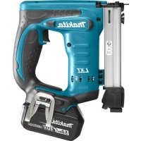
Installing or removing battery cartridge (Fig. 1)

CAUTION:
- Always switch off the tool before installing or removing of the battery cartridge.
- Hold the tool and the battery cartridge firmly when installing or removing battery cartridge. Failure to hold the tool and the battery cartridge firmly may cause them to slip off your hands and result in damage to the tool and battery cartridge and a personal injury.
To remove the battery cartridge, slide it from the tool while sliding the button on the front of the cartridge.
To install the battery cartridge, align the tongue on the battery cartridge with the groove in the housing and slip it into place. Insert it all the way until it locks in place with a little click. If you can see the red indicator on the upper side of the button, it is not locked completely.

CAUTION:
- Always install the battery cartridge fully until the red indicator cannot be seen. If not, it may accidentally fall out of the tool, causing injury to you or someone around you.
- Do not install the battery cartridge forcibly. If the cartridge does not slide in easily, it is not being inserted correctly.
Tool/battery protection system
The tool is equipped with a tool/battery protection system. This system automatically cuts off power to the motor to extend tool and battery life.
The tool will automatically stop during operation if the tool or battery are placed under one of the following conditions. In some conditions, the indicators light up.
(Fig. 2)
Overheat protection for tool
When the tool is overheated, the tool stops automatically and the indicator blinks about 60 seconds. In this situation, let the tool cool before turning the tool on again.
Overheat protection for battery
When the battery is overheated, the tool stops automatically and the battery indicator lights up about 60 seconds. The tool does not start even if pulling the switch trigger. In this situation, let the battery cool before turning the tool on again.
NOTE:
The battery overheat protection works only with a battery cartridge with a star marking. (Fig. 3)
Overdischarge protection
When the remaining battery capacity gets low, the indicator blinks. By further use, the tool stops and the indicator lights up about 60 seconds. In this situation, charge the battery cartridge.
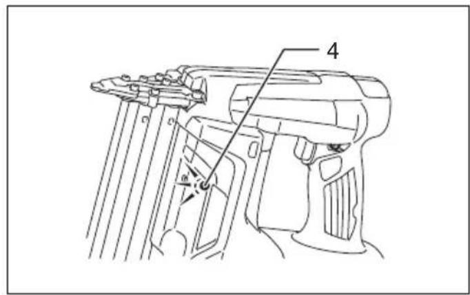
Indicating the remaining battery capacity
(Only for battery cartridges with "B" at the end of the model number.) (Fig. 4)
Press the check button on the battery cartridge to indicate the remaining battery capacity. The indicator lamps light up for few seconds.
 | Remaining capacity | ||
| Lighted Off Blinking | |||
 | 75% to 100% | ||
| 50% to 75% | |||
 | 25% to 50% | ||
| 0% to 25% | |||
 | Charge the battery. | ||
| The battery may have malfunctioned. | |||
015658
NOTE:
- Depending on the conditions of use and the ambient temperature, the indication may differ slightly from the actual capacity.
Using the trigger lock
CAUTION:
- When not in use or after operating the tool, always lock the trigger with the trigger lock. (Fig. 5)
The tool has trigger lock to avoid accidents by an unintentional start. The trigger lock makes the trigger unmovable and let the tool cause no firing.
To lock the trigger, set the lock button in the "LOCK" position.
Before nailing, set the lock button in the "FREE" position. When not in use, always set it in the "LOCK" position and remove the battery cartridge from the tool.
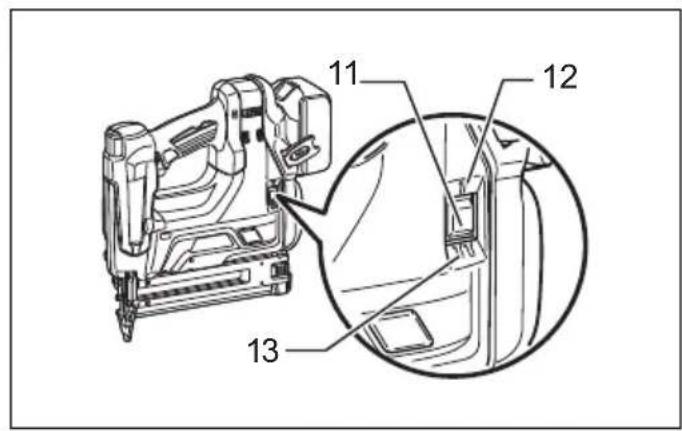
Nailing mode selection (Fig. 6)
The tool has two different nailing modes. Select the desired nailing by the mode selecting button. For more detail, see the section "OPERATION".
Intermittent nailing (sequential mode)
This mode suits for driving a nail carefully and accurately.
Continuous/intermittent nailing (continuous mode)
When the tool is set to this mode, you can choose either continuous or intermittent nailing by sequences of the trigger operation.
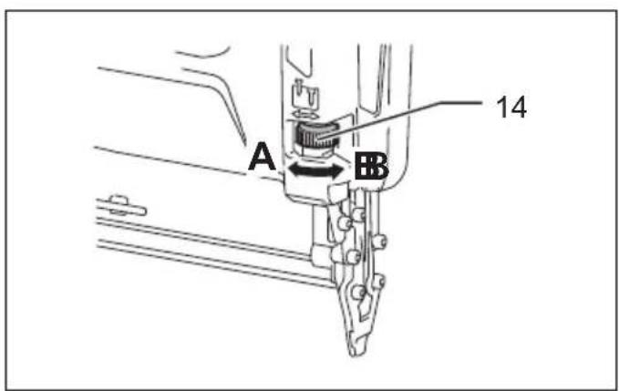
Adjusting the nailing depth
WARNING:
• Always make sure that your fingers are not placed on the trigger, and the battery cartridge and nails are removed. (Fig. 7)
To get shallower depth, turn the adjuster to A direction as shown in the figure. To get deeper depth, turn the adjuster to B direction.
Do not turn the adjuster too much, or the adjuster may get stuck.
Lighting up the lamp
CAUTION:
- Do not look in the light or see the source of light directly. (Fig. 8)
To turn on the lamp, pull the trigger or place the contact element against the workpiece. Release the trigger or contact element to turn it off.
The lamp goes out 10 seconds after releasing the trigger or contact element from the workpiece.
NOTE:
- Use a dry cloth to wipe the dirt off the lens of lamp. Be careful not to scratch the lens of lamp, or it may lower the illumination.
- Even in the lamp lights up when the battery power residual gets small, the nailer may not fire nails. In this case, charge the battery cartridge.
ASSEMBLY
CAUTION:
- Always make sure that your fingers are not placed on the trigger, and the battery cartridge and nails are removed before carrying out any work on the nailer.
Loading or unloading the nails
CAUTION:
- Always make sure that your fingers are not placed on the trigger and the battery cartridge is removed before loading nails.
- Do not abruptly slide the slide door of the nailer loaded with nails. Accidentally dropping nails especially when working in high places may cause personal injuries.
- Load nails in the correct direction. Loading in wrong direction may cause premature wear and tear of the driver and damage of the other parts.
- Do not use deformed connected nails. Use nails specified in this manual. Using nails other than those specified may cause nail jamming and breakage of the nailer.
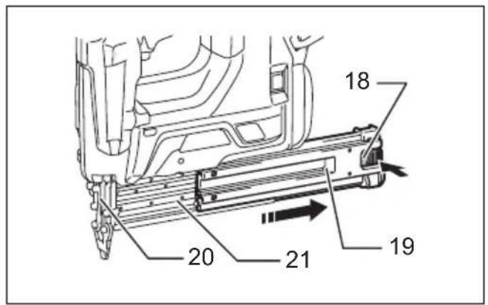
Press the lock lever and open the slide door of the magazine. (Fig. 9)
Set the nail strip so that the nail tips touch the bottom of the magazine slit and slide the nail strip toward the firing opening.
Return the slide door to the original position until the lock lever locks it.
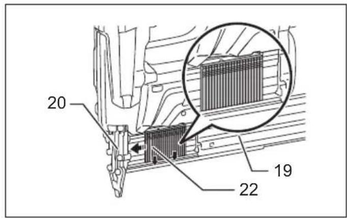
To remove the nails, press the lock lever and slide the slide door. Take out nails from the magazine slit. (Fig. 10)
Nose adapter
CAUTION:
- Always make sure that your fingers are not placed on the trigger, and the battery cartridge and nails are removed before installing the nose adapter. (Fig. 11) When firing nails on the material to be fastened with easily-marred surfaces, use the nose adapter. To install the nose adapter, place it over the center plate so that the protrusion inside the nose adapter fits to the slit in the driver guide cover.
When not in use, store the nose adapter in the holder at the back end of the slide door to keep it from being lost. Total two nose adapters can be stored.
Hook
CAUTION:
- Always make sure that your fingers are not placed on the trigger, and the battery cartridge and nails are removed before using the hook. - Do not hang the hook from the waist belt. Dropping the nailer, which is caused by the hook accidentally coming out of place, may cause misfiring and personal injuries. (Fig. 12)
The hook is convenient for temporarily hanging the tool. This can be installed on either side of the tool.
To install the hook, insert it into a groove in the tool housing on either side and then secure it with a screw. To remove, loosen the screw and then take it out. (Fig. 13)
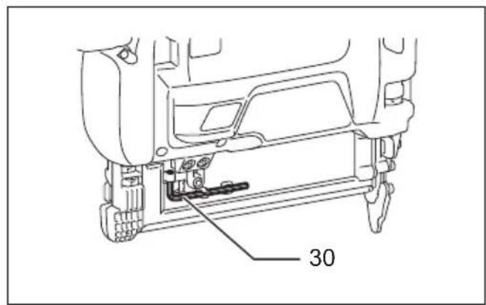
Hex wrench storage (Fig. 14)
When not in use, store the hex wrench as shown in the figure to keep it from being lost.
OPERATION
Inspecting trigger function
CAUTION:
- Make sure that the trigger function is in working order before each operation. If you find issues described below, ask Makita Authorized Service Centers for repairs.
- Before installing the battery cartridge into the tool, always check to see that the switch trigger actuates properly and returns to the "OFF" position when released.
The tool must not operate only by pulling the trigger or only by placing the contact element against the work piece.
Driving nails

CAUTION:
- Always be sure to first place the contact element against the workpiece before pulling the trigger. Select the nailing mode by pressing the mode selecting button as mentioned in the section "Nailing mode selection".
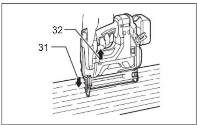
Intermittent nailing (sequential mode) (Fig. 15)
To drive a nail, set the lock button to the "FREE" position. Place the contact element against the workpiece and pull the trigger. Release the trigger after each operation.
Continuous/intermittent nailing (continuous mode) (Fig. 16)
When the tool is set to continuous mode, you can operate either continuous or intermittent nailing.
To drive a nail, set the lock button to the "FREE" position.
- For continuous nailing, pull the trigger first and then place the contact element against the workpiece. For the next actuation, you do not need to release the trigger.
- For intermittent nailing, place the contact element against the workpiece and pull the trigger. For the next actuation, you need to reset the trigger first.
NOTE:
- This tool stops automatically under the following conditions:
- If you release the trigger or contact element from workpiece before the tool finishes the operation completely.
In this situation, pull the trigger again until the tool turns into standby. - When keep either pulling the trigger or placing the contact element about 5 seconds without another action.
In this case, release the trigger or the contact element from workpiece to restart the operation.
Anti dry fire mechanism
This tool is equipped with an anti dry fire mechanism. It automatically stops driving nails when the remaining nails finish. In this case, load more nails to resume operation.
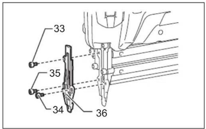
Removing jammed nails

WARNING:
- Always make sure that the trigger is released, and the battery cartridge and nails are removed before removing jammed nails.
Remove hex bolts they are securing the driver guide cover with the hex wrench.
Take the jammed nails from the nail guide groove that has appeared.
Secure the driver guide cover with hex bolts in the correct order. Tighten the hex bolt A, B and then C. (Fig. 17)
NOTE:
- After securing the driver guide cover, always make sure that the driver guide cover actuates properly. If it does not actuate properly, remove hex bolts and install the driver guide cover again.
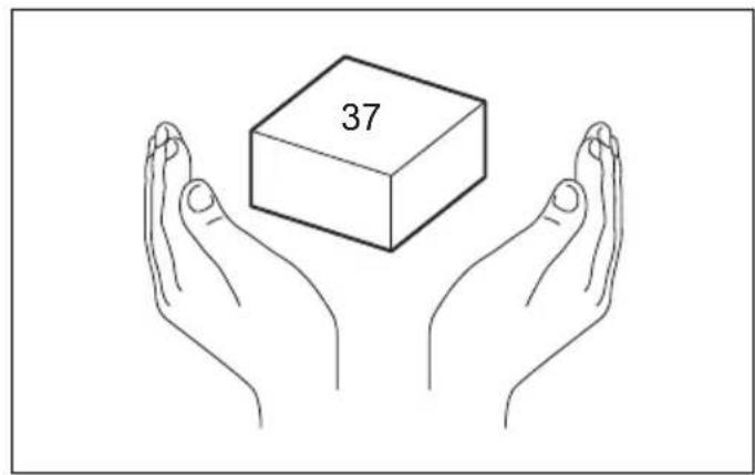
Nails (Fig. 18)
Handle nails and their box carefully. If the nails have been handled roughly, they may be out of shape or their connector breaks, causing poor nail feed.
Avoid storing nails in a very humid or hot place or place exposed to direct sunlight. (Fig. 19)
MAINTENANCE

CAUTION:
- Always be sure that the tool is switched off and the battery cartridge and nails are removed before attempting to perform inspection or maintenance.
- Never use gasoline, benzine, thinner, alcohol or the like. Discoloration, deformation or cracks may result.
Cleaning of magazine
When the pusher in the magazine does not move smoothly because of dust, sand, chips or other foreign matters, clean the magazine.
To remove the slide door, loosen the hex bolt on the magazine. (Fig. 20)
Pull the pusher from the slide door and then remove the stopper, sleeves and springs.
After cleaning, install the whole parts into the slide door.
To install them, take the following procedure. (Fig. 21)
-
Install the large spring into the slide door.
-
Install the parts onto the pusher in the correct order, sleeve, small spring and then stopper.
-
Install the pusher with the other parts onto the slide door.
NOTE:
- When you pull out the pusher from the slide door, the parts in the slide door may bounce out.
- When you install the pusher with the other parts to the slide door, make slight spaces between the pusher and sleeves.
To maintain product SAFETY and RELIABILITY, repairs, any other maintenance or adjustment should be performed by Makita Authorized Service Centers, always using Makita replacement parts.
OPTIONAL ACCESSORIES

CAUTION:
• These accessories or attachments are recommended for use with your Makita tool specified in this manual. The use of any other accessories or attachments might present a risk of injury to persons. Only use accessory or attachment for its stated purpose.
If you need any assistance for more details regarding these accessories, ask your local Makita Service Center.
- Nails
- Makita genuine battery and charger
- Safety goggles
NOTE:
- Some items in the list may be included in the tool package as standard accessories. They may differ from country to country.
Noise
ENG905-1
The typical A-weighted noise level determined according to EN60745:
Sound pressure level (LpA): 79 dB (A)
Uncertainty (K): 3 dB (A)
The noise level under working may exceed 80 dB (A).
Wear ear protection.
Vibration
ENG904-2
The vibration total value determined according to
EN60745:
Vibration emission (a_h) : 2.5m / s^2 or less
Uncertainty (K): 1.5 m/s ^2
ENG901-1
- The declared vibration emission value has been measured in accordance with the standard test method and may be used for comparing one tool with another.
- The declared vibration emission value may also be used in a preliminary assessment of exposure.

WARNING:
- The vibration emission during actual use of the power tool can differ from the declared emission value depending on the ways in which the tool is used.
- Be sure to identify safety measures to protect the operator that are based on an estimation of exposure in the actual conditions of use (taking account of all parts of the operating cycle such as the times when the tool is switched off and when it is running idle in addition to the trigger time).
For European countries only
ENH003-15
EC Declaration of Conformity
Makita declares that the following Machine(s):
Designation of Machine:
Cordless Brad Nailer
Model No./Type: DBN500
Conforms to the following European Directives:
2006/42/EC
They are manufactured in accordance with the following standard or standardized documents:
EN60745, EN792
The technical file in accordance with 2006/42/EC is available from:
Makita, Jan-Baptist Vinkstraat 2, 3070, Belgium
-
- 2015

Yasushi Fukaya
Director
Makita, Jan-Baptist Vinkstraat 2, 3070, Belgium