WX625 - Plane WORX - Free user manual and instructions
Find the device manual for free WX625 WORX in PDF.
User questions about WX625 WORX
0 question about this device. Answer the ones you know or ask your own.
Ask a new question about this device
Download the instructions for your Plane in PDF format for free! Find your manual WX625 - WORX and take your electronic device back in hand. On this page are published all the documents necessary for the use of your device. WX625 by WORX.
USER MANUAL WX625 WORX
- Not all the accessories illustrated or described are included in standard delivery.
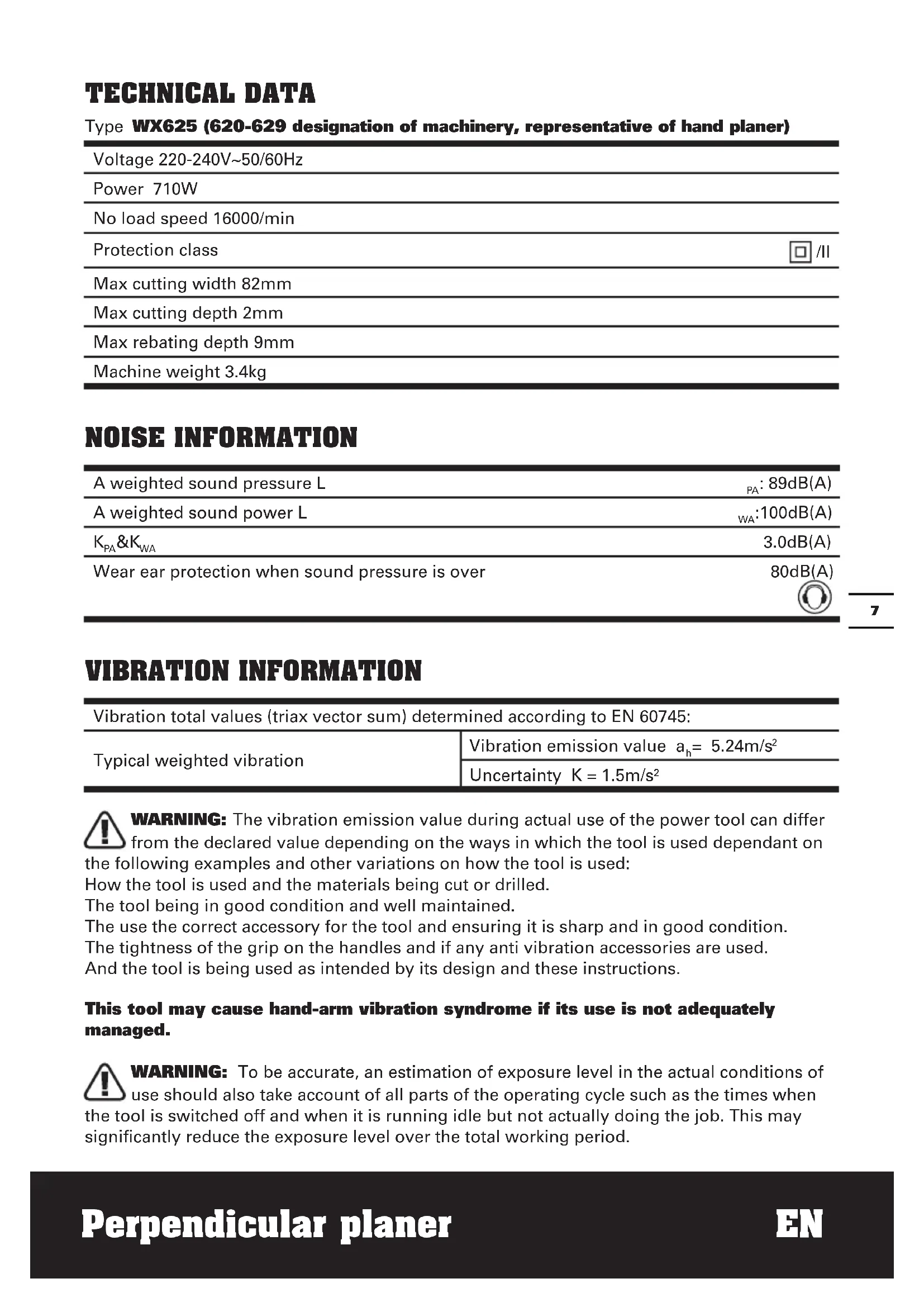
TECHNICAL DATA
Type WX625 (620-629 designation of machinery, representative of hand planer)
| Voltage 220-240V~50/60Hz |
| Power 710W |
| No load speed 16000/min |
| Protection class □/II |
| Max cutting width 82mm |
| Max cutting depth 2mm |
| Max rebating depth 9mm |
| Machine weight 3.4kg |
NOISE INFORMATION
| A weighted sound pressure L | PA: 89dB(A) |
| A weighted sound power L | WA: 100dB(A) |
| KPA&KWA | 3.0dB(A) |
| Wear ear protection when sound pressure is over | 80dB(A) |
VIBRATION INFORMATION
| Vibration total values (triax vector sum) determined according to EN 60745: | |
| Typical weighted vibration | Vibration emission value ah= 5.24m/s2 |
| Uncertainty K = 1.5m/s2 | |

WARNING: The vibration emission value during actual use of the power tool can differ
from the declared value depending on the ways in which the tool is used dependant on
the following examples and other variations on how the tool is used:
How the tool is used and the materials being cut or drilled.
The tool being in good condition and well maintained.
The use the correct accessory for the tool and ensuring it is sharp and in good condition.
The tightness of the grip on the handles and if any anti vibration accessories are used.
And the tool is being used as intended by its design and these instructions.
This tool may cause hand-arm vibration syndrome if its use is not adequately managed.

WARNING: To be accurate, an estimation of exposure level in the actual conditions of
use should also take account of all parts of the operating cycle such as the times when
the tool is switched off and when it is running idle but not actually doing the job. This may
significantly reduce the exposure level over the total working period.
Help to minimize your vibration exposure risk.
ALWAYS use sharp chisels, drills and blades
Maintain this tool in accordance with these instructions and keep well lubricated (where appropriate)
If the tool is to be used regularly then invest in anti vibration accessories.
Avoid using tools in temperatures of 10^ or less
Plan your work schedule to spread any high vibration tool use across a number of days.
ACCESSIONS
Rebate guide 1
Spanner
Perpendicularfence1
TCT blades 2
Only use reversible twin cutting blades that cannot be reground.
1
We recommend that you purchase your accessories from the same store that sold you the tool. Use good quality accessories marked with a well-known brand name. Choose the type according to the work you intend to undertake. Refer to the accessory packaging for further details. Store personnel can assist you and offer advice.
ADDITIONAL SAFETY POINTS FOR YOUR PLANER
- Wait for the cutter to stop before setting the tool down. An exposed rotating cutter may engage the surface leading to possible loss of control and serious injury.
NOTE: The above warning applies only to planers without an automatic closing guard.
- Hold the power tool by insulated gripping surfaces only, because the cutter may contact its own cord.
Cutting a "live" wire may make exposed metal parts of the power tool "live" and could give the operator an electric shock. - Use clamps or another practical way to secure and support the workpiece to a stable platform. Holding the work by your hand or against the body leaves it unstable and may lead to loss of control.
- Always wear a dust mask.
SYMBOLS

To reduce the risk of injury, user must read instruction manual

Warning

Double insulation

Wear eye protection

Wear ear protection

Wear dust mask

Waste electrical products must not be disposed of with household waste. Please recycle where facilities exist. Check with your local authorities or retailer for recycling advice.
OPERATING INSTRUCTIONS

NOTE: Before using the tool, read the instruction book carefully.
INTENDED USE
The machine is intended for planning of firmly supported wooden materials, such as beams and boards. It is also suitable for beveling edges and rebating.
1. SAFETY ON/OFF SWITCH
The switch is locked off to prevent accidental starting. Depress the lock off button (2) then on/off switch (1) and release lock off button (2). The machine is working now. To switch off just release the on/off switch. (See Fig. A)
2. CUTTING DEPTH ADJUSTMENT
Smaller cutting depth of 0-1mm (Max. 2.0mm) is best for most surface planning or rebating. Rotate the cutting depth adjustment (4) to set the required cutting depth on the scale, Scale graduation = 0.125mm . The clockwise rotation increases the planning depth; the counterclockwise rotation reduces the planning depth. (See Fig. B)
3. ADJUST DUST EXTRACTION AND CHIP EJECTION
Dust extraction can be adjusted to the right or left side by manually. Rotate one end of the dust extraction (5) until it stops (See Fig. C). The arrowhead on the dust extraction indicates the dust extraction direction.
NOTE: Due to the size and material of some wood shavings e.g. wet or hard wood it is possible for the dust extraction to become blocked. Remove the plug from the mains power supply, then using a wooden stick clear the blocked dust extraction.
4. BASEPLATE STAND
Uplift the rear of the planer, the base plate stand (6) can make the machine to be set down directly and protect the cutting blades from any damage and the blades from damaging the surface (See Fig. D). When planning, the stand will be pushed away by the end of the wood. Always check the stand is
free to move on the base plate (See Fig. E).
5. BLADE FITTING AND CHANGING
WARNING: Remove power cord from the socket before carrying out any adjustments or changing blades.
The blade has two cutting edges, which can be reversed. When replacing or reversing the plane blades, the guide groove guarantees constant height adjustment.
NOTE: Dull and worn blade cannot be reground and must be replaced.
Remove the plug from the mains socket. Using the spanner (19) provided loosen the 3 bolts approximately 1/2 rotation counterclockwise (See Fig. F). Holding the blade clamp (7) in position, using a piece of wood slides the blade (8) out of the blade clamp (7) to remove the blade from the blade clamp (See Fig. F)
NOTE: There is no need to remove the blade clamp (7) as this can change the factory settings for cutting blade height control. Before reinserting a new or reverse blade, always clean both the blade and the blade seat if dirty. Slide the blade into the blade clamp in the correct orientation. Check the blade is equal with the clamp. When tightening the screws (10) ensure the correct tightening sequence (1, 2, 3). Before starting, rotate by hand to check the roller is free to rotate.
Rotate the blade head by a further 180^ and repeat the procedure disassembling the second plane blade.
6. REPLACING A DRIVE BELT

WARNING:
1) Remove the plug from the socket before carrying out any adjustment, servicing or maintenance.
2) The cutting blades will be turning and may cause injury.
Loosen screw and remove belt cover (11), remove worn drive belt from large pulley (13) and pinion (12) and clean them (See Fig. G). Lace the new drive belt on the top of pinion and turning it manually, press it on the large pulley (13) (See Fig. H).Make sure the drive
belt runs exactly along the length grooves of the pinion and the pulley.
NOTE: Place the belt cover (11) back on top and tighten it with screw.
7. FITTING A DUST BAG
This accessory can be fitted by sliding the dust bag inlet over the planer dust extraction (5) as far as possible. The dust bag will reduce the efficiency of the exhaust system and the bag must be emptied frequently to maintain the efficiency. To empty, open the zip on the rear of the dust bag.
NOTE: This accessory can be used for smaller jobs.
8. EXTERNAL DUST EXTRACTION
The dust extraction (5) is best connected to a suitable external dust extraction machine e.g. vacuum cleaner.
9. REPLACING CARBON BRUSH
WARNING: Always be sure that the tool is switched off and unplugged before attempting to perform inspection or maintenance. The motor brush can be easily accessed the motor housing.

ATTENTION: When servicing a tool,
ALWAYS use only identical replacement
parts.
STEP 1: Locate the plastic motor brush caps on both the front and back of the motor housing.
STEP 2: Remove the threaded brush cap on accessible carbon brush (20) with a flathead screwdriver and turn the screw in a counterclockwise rotation to loosen.
STEP 3: Gently remove the old motor brush.
STEP 4: Carefully insert the replacement brush. Ensure the brush is completely inserted into the holder and is seated properly and is free to move inside its holder.
STEP 5: Replace the brush cap with the flathead screwdriver, turning clockwise to tighten. Do not apply excessive force as this may damage the access brush caps.
10. PERPENDICULAR GUIDE FENCE (18)
The Perpendicular Fence can be used to provide accurate results for all edge planing
operations including squaring the face, straightening an edge and rebating.
18.1 Lock nut (2 places)
18.2 Adjusting turnbuckle (front and rear)
18.3 T section guide
18.4 Locking knob.
18.5 Hand grip.
18.6 Lower datum edge.
18.7 Perpendicular working face.
18.8 Locking bolt (See Fig. N)
A. INSTALLING THE PERPENDICULAR FENCE
Slide the T section guide (18.3) of the
Perpendicular Fence into the T slot (21) in the planer base from the left as shown.
NOTE: It may be necessary to loosen the locking knob (18.4) to allow the Locking Bolt (18.8) to enter the T slot.
Tighten the locking knob to secure the
Perpendicular Fence in the desired position.
B. SETTING THE PERPENDICULAR FENCE POSITION.
The Perpendicular Fence can be set in any position across the planer width.
For wide material, the setting must expose sufficient planer blade to plane the full face width.
For narrow material, the fence setting can be altered to maximize blade life by using different areas of the blade as it becomes worn.
The fence position can also be used to set rebate width (See Fig. K)
C. PLANING A PERPENDICULAR EDGE
The Perpendicular Planer will plane an edge which is perpendicular to another face (usually the wider face) of the work.
The work must be firmly clamped so that both hands can be used to hold and guide the planer.
Hold the planer on the edge to be planned using the planer's top handle in the normal way.
Using the left hand, apply sideways force to hold the face of the Perpendicular Fence against the reference face of the work.
- Plane in the normal way, but maintaining both
downward and sideways pressure.
NOTE: The perpendicular planer cannot correct work where the reference face is twisted.
D. STRAIGHTENING AN EDGE
Perpendicular Fence can be used to plane a straight and perpendicular edge on an inaccurate or irregular edged workpiece.
Mark the position of the desired straight edge at each end of the workpiece.
Measure an offset of dimension below these positions and mark again.
Clamp a straight edge (trusted wood batten or steel section) to the work, its top surface aligned with the offset marks.
Commence planing the edge, keeping material removal reasonably even along the edge, however this is not critical.
As the planed edge approaches the desired position, reduce the planing set depth if necessary for the best finish for the last few passes before the Lower Datum Edge contacts the straight edge.
NOTE: Tapers can also be produced by adjusting the position of the straight edge.
E. FINE TUNING THE PERPENDICULAR FENCE
The Perpendicular Fence is factory adjusted, however the accuracy can be fine tuned by the user.
Use a square to check the fence at each end.
Loosen the lock nut (18.1) and rotate the turnbuckle to move the fence in the correct direction.
Only small adjustments, typically less than 1 turn should be needed.
Re-check with the square and when satisfied hold the turnbuckle whilst retightening the lock nut.
There is no need to excessively tighten the lock nut, just tight is sufficient.
Repeat for each end of the fence.
WORKING HINTS FOR YOUR PLANER

WARNING: Danger of kickback! Apply the machine to the work, be only when switched on.
1. STANDARD SURFACE PLANING
Set the desired cutting depth. Position the front part of the base plate flat onto the work surface. Switch the machine on and push your planer forward and it will start cutting, always maintain all of the base plate flat on the work surface to prevent the cutting blade jumping. Move the plane evenly over the work surface. For most applications 0-2mm max cutting depth will produce a good surface finish. It is best to use small depths of cut and repeat the planning process.
2. EDGE CHAMFERING
Using the V-groove in the base plate (15) you can make a chamfer on the work piece edge (See Fig. I). Guide the planer along the edge and maintain a constant angle and force to produce a good finish. You can control the angle of the chamfer with your hands. Make a test chamfer on a scrap piece of wood. Ensure your work piece is clamped and supported near the edge.
3. REBATING
Fit the Rebate Depth Gauge (16) to your planer. Set the required rebate depth using the scale and the mark on the planer housing next to the scale. Rebate width is set using the Perpendicular Fence (See Fig. J). Loosen locking knob (18.4) and adjust the required rebating width (max 82mm). Tighten locking knob (18.4) Adjust the desired rebating depth with the rebating depth gauge (16) accordingly (max 9mm) (See Fig. K). Plane as often as necessary to achieve the desired rebating depth.
MAINTENANCE
Remove the plug from the socket before carrying out any adjustment, servicing or maintenance.
There are no user serviceable parts in your power tool. Never use water or chemical cleaners to clean your power tool. Wipe clean with a dry cloth. Always store your power tool in a dry place. Keep the motor ventilation slots clean. Keep all working controls free of dust. Occasionally you may see sparks through the ventilation slots. This is normal and will not damage your power tool.
If the supply cord is damaged, it must be replaced by the manufacturer, its service agent or similarly qualified persons in order to avoid a hazard.
ENVIRONMENTAL PROTECTION

Waste electrical products should not be disposed of with household waste. Please recycle where facilities exist.
Check with your local authorities or retailer for recycling advice.
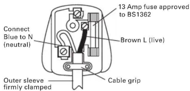
PLUG REPLACEMENT (UK & IRELAND ONLY)
If you need to replace the fitted plug then follow the instructions below.
IMPORTANT
The wires in the mains lead are colored in accordance with the following code:
BLUE = Neutral
Brown = Live
As the colors of the wires in the mains lead of this appliance may not correspond with the colored markings identifying the terminals in your plug, proceed as follows. The wire which is colored blue must be connected to the terminal which is marked with N. The wire which is colored brown must be connected to the terminal which is marked with L.

WARNING: Never connect live or neutral wires to the earth terminal of the Only fit an approved 13A BS1363/A plug he correct rated fuse.
NOTE: If a moulded plug is fitted and has to be removed take great care in disposing of the plug and severed cable, it must be destroyed to prevent engaging into a socket.
DECLARATION OF CONFORMITY
We,
POSITEC Germany GmbH
Declare that the product,
Description WORX Perpendicular planer
Type WX625 (620-629 designation of
machinery, representative of hand planer)
Function Removing surface material with a rotating cutter
Complies with the following Directives,
Machinery Directive 2006/42/EC
Electromagnetic Compatibility Directive
2004/108/EC
RoHS Directive 2011/65/EU
Standards conform to
EN 55014-1
EN 55014-2
EN 61000-3-2
EN 61000-3-3
EN 60745-1
EN 60745-2-14
The person authorized to compile the technical file,
Name Russell Nicholson
Address Positec Power Tools (Europe)
Ltd, PO Box 152, Leeds, LS10 9DS, UK

2013/03/18
Leo Yue
POSITEC Quality Manager
Ltd, PO Box 152, Leeds, LS10 9DS, UK

2013/03/18
LeoYue
INFORMATIONS RELATIVES AU BRUIT
INFORMATIONS RELATIVE AUX VIBRATIONS
Ltd, PO Box 152, Leeds, LS10 9DS, UK


2013/03/18
Leo Yue
Gestor de Qualidade POSITEC
| 1. AAN/UIT-SCHAKELAAR |
| 2. ONTGRENDELINGSSCHAKELAAR |
| 3. HANDGREEPzONES |
| 4. AFSTELLING SCHAAFDIEPTE |
| 5. STOFAFzUIGING |
| 6. VOET GRONDPLAAT (zie D) |
| 7. MESKLEM (zie F) |
| 8. MES (zie F) * |
| 9. SCHAAL SCHAAFDIEPTE |
| 10. SCHROEF (zie F) |
| 11. RIEMAFDEKKING |
| 12. DRIJFWIEL (zie H) |
| 13. GROTE AANDRIJFROL (zie H) |
| 14. GRONDPLAAT |
| 15. V-GROEVEN |
| 16. METER SPONNINGDIEPTE |
| 17. BEVESTIGINGSBOUT |
| 18. LODRECHT VLAK |
| 19. SOKSLEUTEL (zie F) |
| 20. BORSTELKAPPEN (zieJ) |
| 21. T-SLOT BASIS SCHAAFMACHINE |
PO Box 152, Leeds, LS10 9DS, UK


2013/03/18
Leo Yue
6. UDSKIFTNING AF DRIVREM

ADVARSEL:
Ltd, PO Box 152, Leeds, LS10 9DS, UK


2013/03/18
Leo Yue
C. PYSTYSUORAN REUNAN HOYLÄAMINEN
Ltd, PO Box 152, Leeds, LS10 9DS, UK


2013/03/18
Leo Yue
Ilgi Positec Power Tools (Europe) Ltd, PO Box 152, Leeds, LS10 9DS, UK

2013/03/18
Leo Yue
BHMA 3: Aqaipeote npepa tis paiies yntktpes.
BHMA 4: BáIe TIC VÉECS Ψnktpec OiyoupeuovTAC OTI éxouv MTTEI PAnpwC OTNv UTtOdoxN YIA TIC Ψnktpec KAI KIVOUVTAI ELEUθepa.
BHMA 5: BaIe Ta KaTakia Evaio KaTaei yupvWvTac TPOC TIV FOpa Tou poLoyoi yia va Ophiouv. Mny aokite UTePbOaIKn Duvamn yiati mTOpei va Bλaepi Ta KaTakia.
10. KATAKOPYΦOΣ ΦPAXTHΣ OΔHROY (18)
O Katakopoc paxtns mtopei va
xnoiopoiothei yia va npooepovtai akpiñ
aToteAeouata yia oAe ts Aitoupyies
TlavioaTOc akpwv ouPTeipalauabovoevns tnc
TETpawvOToinos TnOuN, TnE uOuypaumionc
ywwivkai nL aEys.
18.1 Naξiμδi αφαλiαης (2 Σημεια)
18.2 Evtatnpac TPOOAPooynC (EPTPOo0Ev kai 0TIOeV)
18.3 Odyoc tmuatoC T
18.4 MoXoG aOgAiaIaIaIaIaIaIaIaIaIaIaIaIaIaIaIaIaIaIaIaIaIaIaIaIaIaIaIaIaIaIaIaIaIaIaIaIaIaIaIaIaIaIaIaIaIaIaIaIaIaIaI
18.5 Xερολβη.
18.6 Kátw akpo aφεπρiας.
18.7 KaTakópuqn oyn εpyaiaç.
18.8 Koxliaac aovapaiiong (EiKN)
A. ERKATAZAHTAOY KATAKOPYFOY φPAXTH
BHIMAHNE: Bn6paun, npoun3bOuIma npn pa6oTe mexaHn3IpoBaHHoro INHCTpyMeHTa,
MOKETOTJINuATbcrO3aBnHbIX3HaueHmB3aBNCIMOCTNOTCNOc0OBNCNoJIb3OBaHn
ycTpoNCTBa. Hnke nepeuHcneHbI HeKOTOpBie ycNoBn, OT KOToPbIX 3aBNCIT INHTeHCNBHOCTb Bn6paun:
Cnocob nCnoB3OBAHnHnHCTpyMeHTa n CBOIcTBa 06pa6aTbIbAemoro MaTePnAna.
CocToHHe IHCTpyMeHTa N ypoBeHb TexO6cnyKuBaHn.
TIN nCnoJIb3yeMbIX npnHaIeXHocTeN INx TeHXueCKoe COCTOHNHe.
Cnla ydepkaHn pykotaK n HaNuHne npOTNBbnpaONHHbIX cpeCTB.
IcnoJIb3yEmble pa6Oue HNCTpyMeHTbl, COOTBeTCTBne npIMeHHeH NHCtpyMeHToB nx Ha3HaYeHNIO.
TCTHOxN (yctaHOBnEhbl Ha MaunHy) 2
NcnoIb3yIte ToIbKO nobopoTHbie HOXn.
PekomeHdyeTc npno6peTaB BCE npnHaJnxHocTn B TOM Je Mara3nHe, rge 6bI npno6peTeH nHCTpyMeHT. IcnoJIb3yIte KaueCTBeHHbIe npnHaJnxHocTn C yka3aHnEM o6uEHN3BecTHoTTOpBOO mApKn. BoJe e NopRo6hIe CBeDeHnA yKa3aHbI Ha yNaKOBKe npnHaJnxHocTeN. POMOu b IN KOHCyIbTaUIO MoXHO TaKKe NoLyuHTb y npOdaBua.
CNEUJIbHbIE IPABNIA BE3OJACHOCTN IPN PABOTE C 3JEKTPNUeCKnM PYBAHKOM
- 3akpennne Te n fckcnpyte 3arotobky Ha cta6nIbHOM OCHOBAHm C NOMOuHO CTpy6uHHbI Hnn dpyrncocobom. EcnBbI 6yndeTe ydepXNBaTb 3arotobky pyko nn npixkMaTb ee K ce6e, ee noJoxHe 6ydet HeIOCTaTOUHO cta6nIbHo, B pe3yIbTaTe Yero BO3MOxHa yTpata KOHTpOJa.
2.ДерхиTe HNCTpyMeHT 3a H3OJInpOBaHHbIe NOBepXHOCTn npH BbINOJIHeHn ONEpaCn, KOrda peKyuSNI HNCTpyMeHT MoKet KocHyTbCra CkpbIToI pNoBODKn.
HaedeHbTe 3aUHTbIe OUKN

Haenbte 3aunTHbIe HayuHnKIn

Haenbtepecnnapot

OTXOdbI 3neKtpoTexHnueckoI npOyKuIN He CneDyeT yTNIn3npoBaTbC 6bITOBbIMN OTXoDAmN. OHN DoJNXbIB6bITb DOCTaBHeHbIB MeCTHbI CEHTp yTNIn3aUIN DnI HaDnEkaeI nepepa60TKn.
3KcPJIyATAUЯ

BHMAHNE: Ipeed nCnoJb3ObaHneM INHCTpyMeHTa, BHIMaTeJbHO npOHTaTe
pyKOBOIDTO NO 3KcNlyatauIN.
ПРИМЕHEHNE NO HA3HAUYEHNIO
HnKn6a3OBbI KpaI (18.6)
NepneHdNkUyIrpHOHa npabJIIOuIeM OXHO
NCNoJIb3OBaTb DJIa CToPraHn IpMaO H
NepneHdNkUyIrpHO rpaHn 3aOTOBK n HeTOUHO
6pa6oTaHHo NII IN MEmIoUeHnPaBnIbHyO
ΦopMy rpaHbIO.
Pa3MeTbTe nOToXeHne Tpe6yEmoN npAmoN rpaHn C kaxdoN CTOpOHbI 3aTOBKn.
I3mepbTe cmeueHne Ha Tpe6yeMoe paccToHne HIXe pa3MeueHHbIX TOUeK I pa3MeTbTe erO.
3aXMMTe 3aROTOBky BmecTe C npraMoN PnAHHoN (depeBraHHoN Nn CTaJIbHOH), COBMeCTNB BepxHIO IOBepxHOCTb PnAHKn C pa3MeueHHOc MceUeHHoN IINHeN.
Haunhaite o6pa6OTky rpaHn 3arotOBKn, paBHomepHo ydaIaC Hee MaTePnaJI (3TO He RAJIaTcKpNTUYeCKN BaXHbIM).
IIO Mepe np6nHexeHnK Tpe6yEmoI φopMe
rpaHn IIO Heo6xOIMOCTN yMeHbShaTe rny6nHy
CTporAHn DnIg o6ecneueHn 60Jee KaYeCTBeHHOrO
pe3yIbTaTHa Na NocNeDnIX HeCKOJIbKnx
IPOXoJax NepeD Tem, KaK HxHn 6a3OBbl KpaI
HanpaBnaHOSeKoCHETc PpMoN pHaHKn.
HnctpyMeHTa, PyuHoI py6aHok)
Функци CBTne NOBepxHocTHoro CNoMaTePnaja BpaaIoMcpeKyuMmMexaHn3MOM
COOTBETCTBYET NOLOXKeHnM DnpeKtNB,
ДиpeктNBa O Maшинан X MexaHn3Max
2006/42/EC
DInpeKTHBa IIO 3JIeKTPOMaHHTHOI
COBMECTHMOCTU 2004/108/EC
DInpeKTHBaIO OpAHHeHnIO nCIOJIb3OBAHnI
BpeHbIX BeIecTB 2011/65/EU
I cTaHdapTaM
EN 55014-1
EN 55014-2
EN 61000-3-2
EN 61000-3-3
EN 60745-1
EN 60745-2-14
JIuO C npaBOM KOMnIIpOBaHn DaHHoro
TEXHnueckoro faaila,
Ltd, PO Box 152, Leeds, LS10 9DS, UK


2013/03/18
Leo Yue
MeHekep no kaueCTby POSITEC

you've got the power
Copyright © 2013, Positec. All Rights Reserved.
2PPL02SPK11001A2