
EY74A3 - Drill PANASONIC - Free user manual and instructions
Find the device manual for free EY74A3 PANASONIC in PDF.
| Product type | Cordless drill driver |
| Brand | Panasonic |
| Model | EY74A3 |
| Motor voltage | 14.4 V DC / 18 V DC (depending on battery) |
| No-load speed (low speed) | 20 - 430 rpm (14.4 V) / 20 - 530 rpm (18 V) |
| No-load speed (high speed) | 70 - 1450 rpm (14.4 V) / 70 - 1800 rpm (18 V) |
| Chuck capacity | 1.5 mm - 13 mm |
| Tightening torque (clutch) | 0.5 N·m - 4.4 N·m (18 settings) |
| Overall length | 189 mm |
| Weight (with battery) | From 1.35 kg (depending on battery) |
| Power supply | Panasonic Li-ion battery (models: EY9L45, EY9L47, EY9L51, EY9L52, EY9L53, EY9L54) |
| Clutch | 18 positions + drill mode |
| Special features | Tapping mode, 3-mode LED lighting, battery level indicator, bit lock, speed control |
| Maintenance | Clean with a dry, clean cloth. Do not use water or solvent. |
| Safety | Overheat protection for motor and battery, voltage reduction, switch lock |
| Included accessories | Keyless chuck, reversible belt hook, spare bit storage |
| Drilling capacities (wood) | Up to 38 mm (18 V) |
| Drilling capacities (metal) | Up to 13 mm |
| Screwing capacities | Machine screw M5, wood screws up to Ø 8 mm |
| Warranty | Warranty supplement. Damage due to prolonged intensive use not covered. |
Frequently Asked Questions - EY74A3 PANASONIC
User questions about EY74A3 PANASONIC
0 question about this device. Answer the ones you know or ask your own.
Ask a new question about this device
Download the instructions for your Drill in PDF format for free! Find your manual EY74A3 - PANASONIC and take your electronic device back in hand. On this page are published all the documents necessary for the use of your device. EY74A3 by PANASONIC.
USER MANUAL EY74A3 PANASONIC
Cordless Drill & Driver
Akku-Bohrschrauber
Percecuse-visseuse sans fill
natural_image
Illustration of a handheld electric drill press with handle and base (no text or symbols)Before operating this unit, please read these instructions completely and save this manual for future use.
| (A) | Keyless drill chuckSchlüsselfreies BohrfutterMandrino porte-foret sans filMandrino autoserranteBoorkop zonder sleutelMandril sin llaveNøglefri borepatronNyckellös borrchuckNøkkelfri drillchuckAvaimeton poran kiinnityslaiteAnahtarsız matkap kovanıBezkluczykowy uchwyt wiertarskiSkličidlo s beznástrojovým upínánímKulcs nélküli fúrótokmány | (B) | Clutch handleKupplungsringPoignée de l'embrayageImpugnatura frizioneKoppelingshandgreepMango de embragueKoblinghåndtagKopplingshandtagKoblingshåndtakKytkimen kahvaKavrama tutamağıPierścień sprzęgłaRukojeť spojkyTengelykapcsolókar |
| (C) | Support handle mounting spaceBefestigungsplatz für ZusatzgriffEspace de montage du manche de supportSpazio per il montaggio della maniglia di sostegnoSteungreep montageruimteEspacio de montaje del mango de soporteMonteringssted for hjælpehåndtagMonteringsmellanrum för stödhandtagMonteringsplass for støttehåndtakTukikahvan asennustilaDestek kolu montaj alanıMiejsce montażu uchwytu pomocniczegoMísto pro montáž podpūrného madlaTartófogantyú rögzítési helye | (D) | Speed selector switchBereichsschalterInterrupteur de sélection de vitesseRegolatore di velocitàSnelheidskeuzeschakelaarInterruptor selector de velocidadHastighedsvælgerHastighetsomkopplareHastighetskontrollNopeuden valintakytkinHiz seçimi anahtarıPrzełącznik wyboru prędkościPřepínač rychlostiFordulatszám-választó kapcsoló |
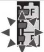
| (E) | Forward/Reverse leverRechts/Linkslauf SchalterLevier d'inversion marche avant-marche arrièreLeva di avanzamento/inversioneVoorwaarts/achterwaarts-hendelPalanca de avance/inversiónGreb til forlæns/baglæns retningRiktningsomkopplareForover/Revers bryterEteenpäin/taaksepäin vipuİleri/Geri koluDźwignia prawo/lewoPáčka Dopředu/dozaduIrányváltó kar | (F) | Belt hookRiemenhakenCrochet de ceintureGancio da cinturaRiemclipGancho del cinturónBæltekrogBälteskrokBeltekrokVyölenkkiKayış kancasıZaczep paskaHák na opasekÖvkampó |
| (G) | Battery packAkkuBatterie autonomePacco batteriaAccuBateríaBatteripakningBatteriBatteripakkeAkkuPil takımıAkumulatorBlok baterieAkkumulátoregység | (H) | Battery pack release buttonAkku-EntriegelungsknopfBouton de libération de batterie autonomeTasto di rilascio pacco batteriaAccu-ontgrendeltoetsBotón de liberación de bateríaUdløserknap til batteripakningFrigöringsknapp för batteriUtløserknapp for batteripakkeAkkupaketin irrotuspainikePil takımı serbest bírakma düğmesiPrzycisk zwolnienia blokady akumulatoraTlačítko uvolnění bloku baterieAkkumulátoregység kioldógombja |
| (I) | Control panelBedienfeldPanneau de commandePannello di controlloBedieningspaneelPanel de controleKontrolpanelKontrollpanelKontrollpanelSäätöpaneeliKumanda paneliPanel sterowaniaik wyboru prędkościOvládací panelKezelőpanel | (J) | Battery level buttonAkkustandsanzeigeknopfBouton de niveau de la batterieTasto di livello della batteriaKnop accuniveauBotón de nivel de la bateríaBatteriniveauknapBatterinivåknappBatterinivåknappAkun lataustasoPil seviyesi düğmesiPrzycisk poziomu naładowania akumulatoraTlačitko stavu baterieAkkumulátor töltésjelzőjének gombja |
| (K) | Battery level indicator/Speed setting indicatorAkkustandsanzeige/Drehzahleinstellungs- sanzeigeIndicateur de niveau de la batterie/Indica-teur de réglage de la vitesseIndicatore di livello della batteria/Indicatore di impostazione della velocitàIndicator accuniveau/Indicator snelheidsin-stellingIndicador de nivel de la batería/Indicador de ajuste de la velocidadBatteriniveauindikator/HastighedsindikatorBatterinivåindikator/VarvtalsindikatorBatterinivåindikator/Indikator for hastighet-sinnstillingAkun lataustason ilmaisin/Nopeusasetuk-sen ilmaisinPil seviyesi göstergesi/Hiz ayar göstergesiWskaźnik poziomu naładowania akumula-tora/Wskaźnik ustawienia prędkościIndikátor stavu baterie/Indikátor nastavení rychlostiAkkumulátor töltésjelzője/Fordulat-szám-beállítás kijelzője | (L) | Speed setting button/Tap mode buttonDrehzahleinstellungsknopf/Schrauben-drehmodus-TasteBouton de réglage de la vitesse/Bouton du mode taraudTasto di impostazione della velocità/Tasto modalità filettaturaSnelheidsinstellingsknop/Tapmodus-knopBotón de ajuste de la velocidad/Botón de modo de roscadorHastighedsvælgerknap/Skærende skrue-indstillingsknappenVarvtalsregleringsknapp/SlaglägesknappKnapp for hastighetsinnstilling/Gjengemo-dus-knappenNopeusasetuspainike/RuuvaustilapainikeHiz ayar düğmesi/Kılavuz açma modu düğmesiPrzycisk ustawiania prędkości/Pprzycisk trybu gwintowaniaTlačitko nastavení rychlosti/Tlačitko závitořezného režimuFordulatszám-beállító gomb/Menetfúró üzemmód gomb |
| (M)(O) | Light buttonLeuchtentasteBouton d’éclairageTasto della luceLichtknopBotón de la luzLysknapLampknappLysknappValopainikeIşık düğmesiPrzycisk oświetleniaTlačitko osvětleniVilágításkapcsoló gombOverheat warning lamp (motor/battery)Überhitzungs-Warnlampe (Motor/Akku)Témoin d'avertissement de surchauffe (moteur/batterie)Spia avvertenza surriscaldamento (motore/batteria)Oververhitting-waarschuwingslampje (motor/accu)Luz de advertencia de sobrecalentamiento (motor/batería)Advarselslamp til overophedning (motor/batteri)Varningslampa för överhettning (motor/batteri)Varsellampe for overoppheting (motor/batteri)Ylikuumenemisen varoituslamppu (moottori/akku)Aşırı ısınma uyarı lambası (motor/batarya)Lampka ostrzegawcza przegrzania (silnik/akumulator)Kontrolka přehřátí (motor/baterie)Túlmelegedésre figyelmeztető lámpa (motor/akkumulátor) | (N)(P) | Tap mode indicatorSchraubendrehmodus-AnzeigeIndicateur du mode taraudIndicatore modalità filettaturaTapmodus-indicatorIndicador de modo de roscadorSkærende skrue-indstillingsindikatorSlaglägesindikatorGjengemodus-indikatorRuuvaustilan merkkivaloKılavuz açma modu göstergesiWskaźnik trybu gwintowaniaIndikátor závitořezného režimuMenetfúró üzemmód jelzőfényVariable speed control triggerBetriebsschalterGâchette de commande de vitesseGrilletto di controllo velocità variableStartschakelaar variabele snelheidDisparador del control de velocided variableKontroludløser for variabel hastighedSteglös varvtalsreglerareHovedbryter, trinnløsNopeudensäätökytkinDeğişken hızlı kumanda tetikleyiciJęzyk spustowy z płynną regulacją prędkościSpoušť proměnlivé rychlostiFordulatszám-szabályozós indítókapcsolól |
| (Q) | LED lightLED-LeuchteLumière DELLuce LEDLED-lampjeLuz indicadoraLED-lysLED-ljusLED-lysLED-valoLED ışığıLampka LEDLED osvětleníLED-lámpa | (R) | Battery chargerLadegerätChargeur de batterieCaricabatterieAcculaderCargador de bateríaBatteriopladerBatteriladdareBatteriladerAkkulaturiPil şarj cihazıŁadowarkaNabíječka baterieAkkumulátortöltő |
| (S) | Alignment marksAusrichtmarkierungenMarques d'alignementMarcature allineamentoUitlijntekensMarcas de alineaciónFlugtemærkerAnpassningsmärkenOpprettingsmerkeSovitusmerkitHizalama işaretleriZnacznikiRovnací značkyPozíciójelölések | (T) | Pack coverAkkuabdeckungCouvercle de la batterie autonomeCoperchio paccoAccudekselCubierta de bateríaPakningsdækselBatteriskyddPakkedekselAkkukotelon kansiPil takımı kapağıOsłona akumulatoraKryt blokuAz akkumulátoregység fedele |
| (U) | Spare bit storageErsatzbit-AblageRangement des mèches de rechangeMagazzino punte di scortaReserve-bitopslagAlmacenamiento de brocas de recambioMagasin til ekstra bit | Förvaring av reservbettReservebit-lagerVaraterien säilytyslaatikkoYedek bits uç muhafaza haznesiMagazynek zapasowych końcówekÚložiště náhradních bitůTartalék fej tároló |
NOTE: Not all battery packs display the alignment mark (S).
![[Fig.3] ① ②](/content/2026/03/461742/images/47f8091ac4e1af21480783de350c3f65e254cfbe8791c229d95fee12c2da5652.jpg)
![[Fig.4] Alignment marks Ausrichtmarkierungen Marques d'alignement Marcature allineamento Uitlijntekens Marcas de alineación Flugtemærker Anpassningsmärken Opprettingsmerke Sovitusmerkit Hizalama işaretleri Znaczniki Rovnaci značky Pozíciójelölések Button Knopf Bouton Tasto Knop Botón Knap Frigöringsknapp Knapp Painike Düğme Przycisk Tlačítko Gomb](/content/2026/03/461742/images/931aa23287587b66e1c20416a4a881ce2080ddde7334b8cce8397ec4f370f7a0.jpg)
![[Fig.5] Forward Rechts Rotation en sens normal Avanti Rechts Avance Forlæns Framåt Forover Eteenpäin Ileri Prawo Dopředu Jobbra Switch lock Schaltersperre Verrouillage du commutateur Blocco interruttore Vergrendelstand Bloqueo delinterruptor Omskifterlås Låst läge Bryterlås Kytkinlukko Anahtar kilidi Blokada przełącznika Zámek spouště Kapcsoló retesze Reverse Links Rotation en sens inverse Inversione Links Marcha atrás Baglæns Bakåt Bakover Taaksepäin Geri Lewo Dozadu Balra](/content/2026/03/461742/images/16f4845204d18fe1611778ee9bb68b5b8bde7ec35f824cecd363c75b3d394999.jpg)
![[Fig.6]](/content/2026/03/461742/images/6a2f50ba6462726a7228efd81aac979e14d97b8c3911af88e3026f5277a04a2a.jpg)
![[Fig.7] LOW NIEDRIG BAS BASSO LAAG BAJA LAV LÁGA VARVTAL LAV PIENI DÜŞÜK LOW NÍZKÝ ALACSONY HIGH HOCH HAUT ALTO HOOG ALTA HØJ HÖGA VARVTAL HØY SUURI YÜKSEK HIGH VYSOKÝ MAGAS](/content/2026/03/461742/images/258a7bc693d11767dbac1bed856b67389c681a0fdf30494a7898d10af9ea1bed.jpg)
natural_image
Illustration of a hand using a power tool to lift a square block, no text or symbols present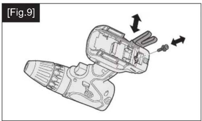
natural_image
Technical line drawing of a disassembled electric drill bit with internal components and directional arrows indicating motion (no text or symbols)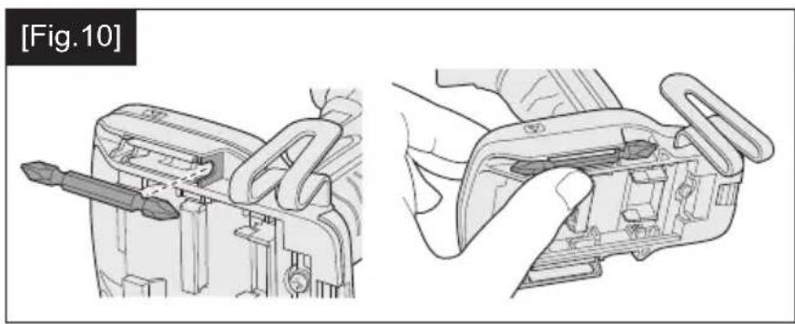
natural_image
Technical illustration of a mechanical device with tool and component views (no text or symbols)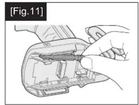
natural_image
Close-up of hands installing or adjusting a mechanical component, no visible text or symbols![[Fig.12] Pack cover Akkuabdeckung Couvercle de la batterie autonome Coperchio pacco Accudeksel Cubierta de batería Pakningsdæksel Batteriskydd Pakkedeksel Akkukotelon kansi Pil takımı kapağı Osłona akumulatora Kryt bloku Az akkumulátoregy- ség fedele Label (red or yellow) Etikett (rot oder gelb) Etiquette (rouge ou jaune) Etichetta (rossa o gialla) Label (rood of geel) Etiqueta (roja o amarilla) Label (rödt eller gult) Etikett (röd eller gul) Etikett (röd eller gul) Tarra (punainen tai keltainen) Etiket (kırmızı veya sarı) Etykieta (czerwona lub żółta) Etiketa (červená nebo žlutá) Címke (piros vagy sárga) Terminals Anschlüsse Bornes Terminali Aansluitpunten Terminales Terminaler Poler Ender Liittimet Terminaller Styki Konektory Érintkezők](/content/2026/03/461742/images/b7c85a560869f5bec6b236d7a814fdf7f5ad64a3d92e29a4f2192086669d9d6e.jpg)
[Fig.13]
Battery pack release button — Akku-Entriegelungsknopf Bouton de libération de batterie autonome Tasto di rilascio pacco batteria Accu-ontgrendeltoets Botón de liberación de batería Udløserknap til batteripakning Frigöringsknapp för batteri Utløserknapp for batteripakke Akkupaketin irrotuspainike Pil takımı serbest bırakma düğm Przycisk zwolnienia blokady aku Tlačítko uvolnění bloku baterie Akkumulátoregység kioldógomb
![PANASONIC EY74A3 - [Fig.13] - 1](/content/2026/03/461742/images/a8795703bd0139e723048a4029951ea76c4917cffb748803dcd996b817bf1df9.jpg)
natural_image
Diagram of a device with an attached device and directional arrows indicating motion (no text or symbols)Alignment marks Ausrichtmarkierungen Marques d'alignement Marcature allineamento Uitlijntekens Marcas de alineación Flugtemærker Anpassningsmärken Opprettingsmerke Sovitusmerkit Hizalama isaretleri Znaczniki Rovnaci značky Pozíciójelölések
![PANASONIC EY74A3 - [Fig.13] - 2](/content/2026/03/461742/images/d9ed00b667835b325bf9f26ee55ec5dfac19ecf46fd79d27111749432cf77ea5.jpg)
![PANASONIC EY74A3 - [Fig.13] - 3](/content/2026/03/461742/images/8709956ec4f94168d1d6bbe789e854151702444e4d1b915157336f4a9444081c.jpg)
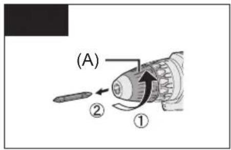
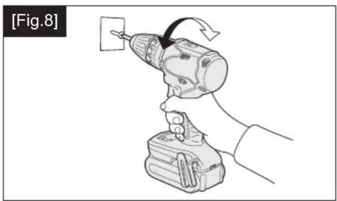
Attaching Anbringen Connexion Collegamento Bevestigen Acoplamiento Påsætning Montering Montering Kiinnittäminen Takma Mocowanie Nasazení Csatlakoztatás
Removing Entfernen Retrait Rimozione Verwijderen Desacoplamiento Aftagning Lossdragning Demontering Irrottaminen Çıkarma Wyciaganie Sejmutí Eltávolítás
Original instructions: English Translation of the original instructions: Other languages
Read "the Safety Instructions" booklet and the following before using.
I. INTENDED USE
These tools can be used to tighten screws in clutch mode and to drill holes in wood and metal in drill mode.
II. ADDITIONAL SAFETY RULES
1) If the bit becomes jammed, immediately turn the trigger switch off to prevent an overload, which can damage the battery pack or motor. Use reverse motion to loosen jammed bits.
2) Do NOT operate Forward/Reverse lever when the trigger switch is on. The battery will discharge rapidly and damage to the main unit may occur.
3) During charging, the charger may become slightly warm. This is normal. Do NOT charge the battery for a long period.
4) Do not strain the tool by holding the speed control trigger halfway (speed control mode) so that the motor stops.
5) To prevent injury during use, hold the tool steady at all times and avoid waving it around.
6) Ensure that there are no hidden gas or water pipes in the area in which you will be working. Contact with hidden pipes or wires could cause electric shock or water or gas leaks.
7) Make sure to hold the object you are working on steady.
8) Check for damaged parts.
- Check thoroughly for damage to the protective cover and other parts before operating.
- Check to make sure the tool and all of its functions are working properly.
- Check the adjustment of all movable parts, and check all fixed parts to make sure they are fitted properly and free of damage. Check all parts of the tool for abnormal function.
9) When attempting to repair the protective cover or other parts, please follow the instructions in the user manual. In cases where there are no instructions in the manual, please take it back to the store to have it repaired.
10) If the tool gets exceptionally hot during use, please take it in for service and repair.
11) To avoid potential injury, keep face and hands away from the drill bit and any shavings.
12) Do not wear gloves when operating the tool, as they may get caught by the drill, leading to injury.
13) Battery terminals, screw shavings, and tool accessories such as drill bits will be very hot immediately after operation. Do not touch them as there is a risk of burning yourself.
| Symbol Meaning | |
| V | Volts |
| --- | Direct current |
| n_0 | No load speed |
| ... min^-1 | Revolutions or reciprocations per minutes |
| Ah | Electrical capacity of battery pack |
| Rotation only | |
 | Read the operating instructions before use. |
 | For indoor use only. |
WARNING
- Do not use other than the Panasonic battery packs that are designed for use with this rechargeable tool.
- Panasonic is not responsible for any damage or accident caused by the use of recycled or counterfeit battery pack.
- Do not dispose of the battery pack in a fire, or expose it to excessive heat.

WARNING
- Do not allow metal objects to touch the battery pack terminals.
- Do not carry or store the battery pack in the same container as nails or similar metal objects.
- Do not charge the battery pack in a high-temperature location, such as next to a fire or in direct sunlight. Otherwise, the battery may overheat, catch fire, or explode.
• After removing the battery pack from the tool or the charger, always reattach the pack cover. Otherwise, the battery contacts could be shorted, leading to a risk of fire. - When the Battery Pack Has Deteriorated, Replace It with a New One. Continued use of a damaged battery pack may result in heat generation, ignition or battery rupture.
• To prevent leakage, overheating, smoke generation, fire, and rupturing from occurring, follow these instructions when handling our rechargeable power tools (tool main body/battery pack/charger).
- Do not allow material cuttings or dust to fall onto the battery pack.
- Before storing, remove any material cuttings and dust from the battery pack, fit red plastic “terminal cover”, then place separately from metal objects (screws, nails, etc.) in tool case. Damage caused by loose objects in the case will not be covered by warranty.
- Do not handle the rechargeable power tools in the following way. (There is a hazard of smoke generation, fire, and rupturing)
- Use or leave in places exposed to rain or moisture
- Use submerging in water
III. ASSEMBLY
Attaching or Removing Bit
NOTE:
Disconnect battery pack from the main unit or place the switch in the center position (switch lock).
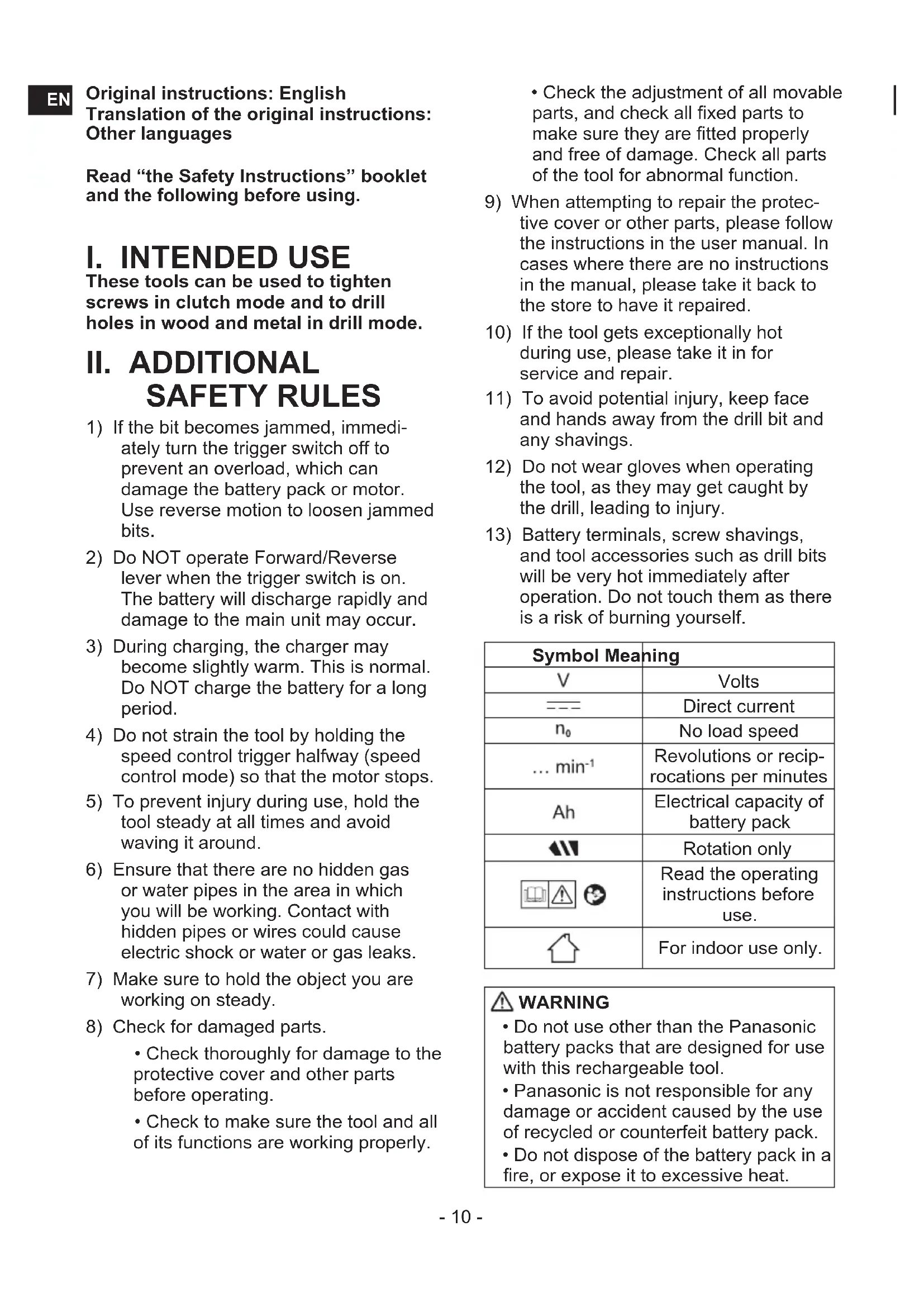
The main unit is equipped with a keyless drill chuck.
- Attachment
Insert the bit and turn the lock collar clockwise (looking from the front) to tighten firmly until it stops clicking. [Fig.1]
- Removal
Turn the lock collar counterclockwise (looking from the front), then remove the bit. [Fig.2]
NOTE:
If there is excessive play in the chuck, secure the drill in place and open the chuck jaws by turning the lock collar and tighten the screw (left-handed screw) with a screwdriver by turning it counterclockwise (viewed from the front). [Fig.3]
Attaching or Removing Battery Pack
NOTE:
When the battery pack is removed from the main unit, the control panel lamp may light up briefly. This is not a malfunction.
- To attach the battery pack: [Fig.4]
Align the highlighted marker points and attach battery pack.
Slide the battery pack until it locks into position.
- To remove the battery pack: [Fig.4]
Push the button and slide the battery pack forward.
IV. OPERATION

WARNING!
- Do not inhale smoke emitted from the main unit or battery pack as it may be harmful.
[Main Unit]
CAUTION
When storing or carrying the tool, set the Forward/Reverse lever to the center position (switch lock).
NOTE:
Exercise caution to ensure no objects come into contact with the tool's trigger switch.
Switch and Forward/Reverse Lever Operation [Fig.5]
Push the lever for forward or reverse rotation. Check the direction of the lever before using.
CAUTION:
When operating the tool by pulling the trigger, there may be a momentary lag before rotation starts. This does not signal a malfunction.

CAUTION:
To prevent damage, do not operate Forward/Reverse lever until the bit comes to a complete stop.
Clutch Torque Setting
Adjust the torque to one of the 18 clutch settings or “” position.

CAUTION:
- Set the clutch setting at this mark ◀ [Fig.6] before actual operation.
- If the clutch handle cannot be set at "drilling" mode after driving with clutch function, set the clutch handle at position 1 and operate the clutch for a second.
Speed Selection
Choose a low or high speed to suit the use. [Fig.7]
The more the variable speed control trigger is pulled, the higher the speed becomes.

CAUTION:
- Check the speed selector switch before use.
- Use in low gear when high torque is required in operation. (Using in high gear with high load can cause motor overload and possible failure.)
- To prevent excessive temperature increase of the tool surface, do not operate the tool continuously using two or more battery packs. The tool needs cool-off time before switching to another pack.
- Ensure that air vents on the sides of the main unit are not blocked during operation. Covering them can cause the tool to overheat and motor damage to occur.
- Do NOT strain the tool (motor). This may cause damage to the tool.
- Avoid contact with air from vent holes during operation as under heavy load this can become hot and potentially cause injury.
Speed Control Function
Setting the maximum speed.
-
Press the Speed setting button/Tap mode button (L) and select a speed. The speed changes to H, M, L and OFF (the light is off) in this order.
-
Select OFF to release it.
| Display | Low mode | |
| H Approx. | 300 min | -1(rpm) |
| M Approx. | 200 min | -1(rpm) |
| L Approx. | 150 min | -1(rpm) |
| OFF Ordinary speed | ||
| 18 V Approx. | 530 min -1(rpm) | |
| 14.4 V Approx. | 430 min -1(rpm) | |
| Display | High mode | |
| H Approx. | 1000 min | -1 (rpm) |
| M Approx. | 670 min | -1 (rpm) |
| L Approx. | 500 min | -1 (rpm) |
| OFF Ordinary speed | ||
| 18 V Approx. | 1800 min -1 (rpm) | |
| 14.4 V Approx. | 1450 min -1 (rpm) | |
- Default setting: OFF
- The speed is the same using either 14.4 V or 18 V when H, M, L settings are selected.
- If a high mode is chosen, the speed is set as the table above.
Tap mode
- Regardless of the position of the Forward/Reverse lever (E), every time the trigger switch is pressed, the drill switches between “forward” and “reverse”.
Check the "FWD" and "REV" lamps when working.
The lamp lights up in accordance with "forward" or "reverse".
NOTE:
- When using the Tap mode function, the tap drill may be damaged, so set the clutch handle at position 1 before use.
- Tip tools (tap drills) may slip during work depending on the shape, type, and surface condition.
In order to ensure safe and accurate work, before starting work or during work, check that the tip tool (tap drill) is securely tightened with the keyless drill chuck. Also, use a hexagonal shaft type tip tool (tap drill) with high holding force when you wish to perform more accurate work.
- Tap mode is cancelled when no operation is performed for about 5 minutes or immediately after the battery pack is removed.
Tap mode settings
-
Press and hold the Speed setting button/Tap mode button (L) for 2 seconds or longer.
The Tap mode lamp "FWD" lights up. -
In Tap mode, press the Speed setting button/Tap mode button (L) to change the rotational speed.
The speed changes to L, H, M in this order.
NOTE:
- To cancel Tap mode, press and hold the Speed setting button/Tap mode button (L) for 2 seconds or longer. The Tap mode lamp turns off.
- During Tap mode, the rotational speed is the same for motor voltage of both 18 V DC and 14.4 V DC
3 Mode LED Light
Press the light button to select illumination setting.
Illuminated - Constant
Select by pressing lamp button light will activate when trigger is pressed. It will then stay illuminated for approximately 5 minutes even if tool is not used but will then switch off automatically to save power.
Illuminated - On trigger
By pressing the lamp button again, the mode will move to illumination upon the pressing of the trigger only.
Off

CAUTION:
Do not use it as a substitute for a regular flashlight, since it does not have enough brightness.
CAUTION: DO NOT STARE INTO BEAM.
Use of controls or adjustments or performance of procedures other than those specified herein may result in hazardous radiation exposure.
Battery Level Indicator
Press the battery level button.
NOTE:
The indicator will not show the battery level when the button is pressed in the following cases.
• The tool is powered off.
- Just after attaching the battery pack
- The main unit or battery level button is not operated for approx. five minutes. Press the battery level button again after depressing the trigger switch.
| Indicator Battery status | ||
 | 3 lamps illuminated | Fully charged or high charge level |
 | 2 lamps illuminated | Approx. 60% remaining |
 | One lamp illuminated | Low level- Will require charging soon |
| KKDZ] | 3 lamps flashing | Empty -Immediate charging required |
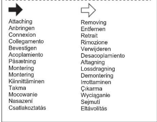
Bit-locking Function
- With the trigger switch not depressed and a screwdriver bit locked in place, the tool can be used as a manual screwdriver (up to 22.6 N·m, 230 kgf·cm, 199 in·lbs).
- This feature is handy for tightening screws that require more torque than the maximum torque of the driver (position on the clutch), for confirming the tightness of a screw or to loosen an extremely tight screw. [Fig.8]
Changing the Belt Hook Location Side [Fig.9]
The belt hook can be attached to either side of the unit.
![PANASONIC EY74A3 - Changing the Belt Hook Location Side [Fig.9] - 1](/content/2026/03/461742/images/6d36faace960d82e1f9f18740a824db177ce29ff064c69c49bcf4edf1a5763d2.jpg)
WARNING!
- Be sure to attach the belt hook securely to the main unit with the screw firmly fastened.
• Periodically check screw for tightness. If found to be loose, tighten firmly. - When the tool is held by the belt hook, avoid jumping or running with it.

WARNING!
- When the tool is hooked onto the waist belt by the belt hook, do not attach driver bits to the tool. A sharp edge object, such as a drill bit, may cause injury or an accident.
How to use spare bit storage
- Store spare bits.
1 Remove the battery pack.
2 Push it all the way into the spare bit storage as shown in [Fig.10].
- Remove spare bit from storage. [Fig.11]
1 Remove the battery pack.
2 Pull out the bit tip on the rear side of the spare bit and take out the bit.
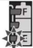
Warning Functions
(1) Overheat Warning

Off (normal operation)
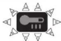
Illuminated: Overheat (motor)
Flashing: Overheat (battery)
Indicates operation has been halted due to motor or battery overheating.
- If the overheating protection feature activates, allow the tool to cool thoroughly (at least 30 minutes). The tool is ready for use when the overheat warning lamp goes out.
- Avoid using the tool in a way that causes the overheating protection feature to activate repeatedly.
- The performance of the EY9L42 deteriorates significantly at and below 10^ due to work conditions and other factors.
(2) Voltage Reduction Warning

Three lamps flashing
If the tool is subject to a sudden load during use that causes the motor to lock up, the overdischarge prevention sensor may be
triggered, and the battery low warning lamp may flash. The lamp will stop flashing once you address the cause of the motor's locking up and cycle the trigger.
[Battery Pack]
For Appropriate Use of Battery Pack [Fig.12]
- For optimum battery life, store the Li-ion battery pack following use without charging it.
- When operating the battery pack, make sure the work place is well ventilated.
For safe use
- If the battery pack is not connected firmly when the switch is switched on, the overheat warning lamp and the battery low warning lamp will flash to indicate that safe operation is not possible, and the main unit will not rotate normally. Connect the battery pack into the unit of the tool until the red or yellow label disappears.
- Only use rechargeable battery packs for Panasonic rechargeable tools. Do not use modified battery packs (including battery packs which have been disassembled and parts replaced).
- Do not use deteriorated battery packs. There is a risk of the generation of heat, ignition and explosion.
- If a battery pack leaks fluid, cease use, keep away from open flames, and return it to the store immediately.
- Attach the battery pack by sliding until the yellow and red labels are no longer visible, and check that it does not fall out of place.
- Failure to do so may result in scalding.
- The usage temperature range for lithium ion battery packs is 0 to 40 degrees.
- Use of battery packs cooled to below zero, such as in colder northern areas, may result in abnormal operation of the device. In such cases, leave the battery pack in a location of 10 degrees or more for one hour or more before use, and only use the device after the battery pack has warmed up.
[Battery Charger]
Charging
CAUTION:
1) If the temperature of the battery pack falls approximately below -10^ ( 14^ ), charging will automatically stop to prevent degradation of the battery.
2) The ambient temperature range is between 0^ C ( 32^ F) and 40^ C ( 104^ F).
If the battery pack is used when the battery temperature is below 0^ C ( 32^ F), the tool may fail to function properly.
3) Use the charger at temperatures between 0^ C and 40^ C, and charge the battery at a temperature similar to that of the battery itself. (There should be no more than a 15^ C difference between the temperatures of the battery and the charging location.)
4) When charging a cool battery pack (below 0^ C ( 32^ F)) in a warm place, leave the battery pack at the place and wait for more than one hour to warm up the battery to the level of the ambient temperature.
5) Cool down the charger when charging more than two battery packs consecutively.
6) Do not insert your fingers into contact hole, when holding charger or any other occasions.
7) Unplug the charger when not in use.
8) Store the charger between 0 and 40 degrees, and charge the battery pack at a temperature close to the storage temperature.
- If the battery pack is charged while at a temperature below 0 degrees, a full charge will give only around 50% of a normal charge. Commence charging after 1 hour or more at the prescribed temperature.
9) Do not charge in a poorly ventilated place.
NOTE:
Your battery pack is not fully charged at the time of purchase. Be sure to charge the battery before use.
How to charge
- Plug the charger into the AC outlet.
NOTE:
Sparks may be produced when the plug is inserted into the AC power supply, but this is not a problem in terms of safety.
- Connect the battery pack firmly into the charger.
1 Line up the alignment marks and place the battery onto the dock on the charger.
NOTE:
Not all battery packs display the alignment mark (S) (on page 2).
2 Slide forward in the direction of the arrow. [Fig.13]
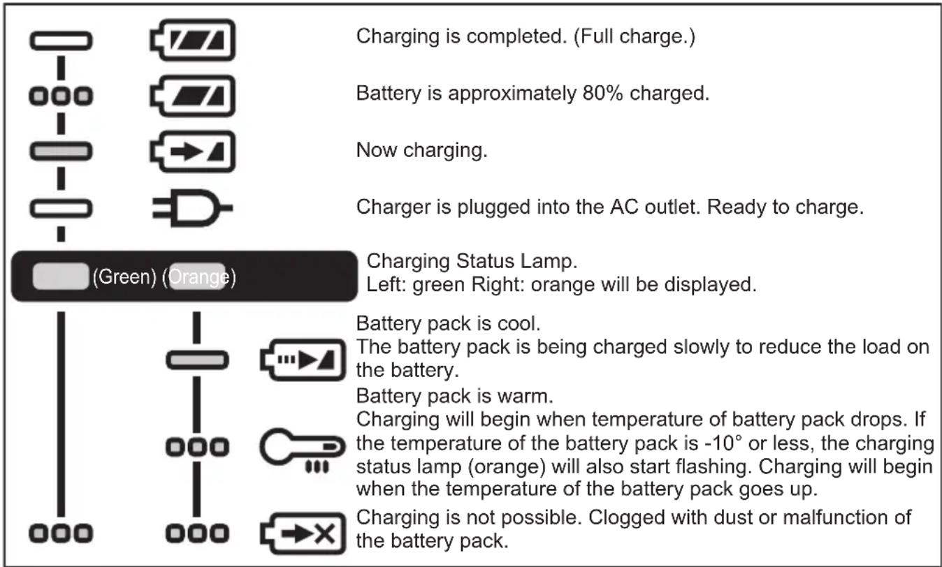
- During charging, the charging lamp will be lit. When charging is completed, an internal electronic switch will automatically be triggered to prevent overcharging.
- Charging will not start if the battery pack is hot (for example, immediately after heavy-duty operation). The orange standby lamp will be flashing until the battery cools down. Charging will then begin automatically.
-
The charge lamp (green) will flash slowly once the battery is approximately 80% charged.
-
When charging is completed, the charging lamp in green color will turn off.
-
If the temperature of the battery pack is 0^ C or less, charging takes longer to fully charge the battery pack than the standard charging time. Even when the battery is fully charged, it will have approximately 50% of the power of a fully charged battery at normal operating temperature.
-
Consult an authorized dealer if the charging lamp (green) does not turn off.
-
If a fully charged battery pack is inserted into the charger again, the charging lamp lights up. After several minutes, the charging lamp in green color will turn off.
-
Remove the battery pack while the battery pack release button is held up. [Fig.13]

Turn off Illuminated

Flashing
Battery Recycling
ATTENTION:
For environmental protection and recycling of materials, be sure that it is disposed of at an officially assigned location, if there is one in your country.
These symbols indicate separate collection of waste electrical and electronic equipment or waste batteries.
More detailed information is contained in the full version Operating Instructions.
https://www.panasonic-powertools.eu/en/construction/documents.htm
V. MAINTENANCE
- Use only a dry, soft cloth for wiping the unit.
Do not use a damp cloth, thinner, benzine, or other volatile solvents for cleaning. - In the event that the inside of the tool or battery pack is exposed to water, drain and allow to dry as soon as possible. Carefully remove any dust or iron filings that collect inside the tool. If you experience any problems operating the tool, consult with a repair shop.
VI. ACCESSORIES
- Use only bits suitable for size of drill's chuck.
- Support handle
WEY6470K3217
MAXIMUM RECOMMENDED CAPACITIES
| Model No. EY74A3 | |||
| Motor voltage 14.4 V DC 18 V DC | |||
| Screw driving Ma | chine screw M5 | ||
| Wood screw Φ 6.8 mm Φ 8 mm | |||
| Drilling Self-drilling | g screw Φ 6 mm | ||
| For Wood Φ 35 mm Φ 38 mm | |||
| For Metal Φ 13 mm | |||
WARRANTY SUPPLEMENT
The breakdown and damage caused by usage consistent for a long time (e.g.: factory work on the assembly line, etc.) is out of warranty.
VIII. SPECIFICATIONS
NOTE: Weight indication
Greater than or equal to 1 kg: indicated by 0.05 kg.
Less than 1 kg: indicated by 0.01 kg.
MAIN UNIT
| Model No. | EY74A3 | ||
| Motor voltage | 14.4 V DC | 18 V DC | |
| No load speed | Low | 20 – 430 min ^-1 (rpm) | 20 – 530 min ^-1 (rpm) |
| High | 70 – 1450 min ^-1 (rpm) | 70 – 1800 min ^-1 (rpm) | |
| Chuck capacity | 1.5 mm – 13 mm | ||
| Clutch torque | Approx. 0.5 N•m – 4.4 N•m | ||
| Overall length | 189 mm | ||
| WeightWith battery pack: | EY9L45 | 1.55 kg | — |
| EY9L47 | 1.35 kg | — | |
| EY9L51 | — | 1.95 kg | |
| EY9L52 | — | 2.00 kg | |
| EY9L53 | — | 1.75 kg | |
| EY9L54 | — | 2.00 kg | |
| Noise, Vibration | See the included sheet | ||
ONLY FOR U. K.
IX. CAUTION FOR AC MAINS LEAD
FOR YOUR SAFETY PLEASE READ THE FOLLOWING TEXT CAREFULLY
This appliance is supplied with a moulded three pin mains plug for your safety and convenience. A 5 amp fuse is fitted in this plug.
Should the fuse need to be replaced please ensure that the replacement fuse has a rating of 5 amp and that it is approved by ASTA or BSI to BS1362.
Check for the ASTA mark for the BSI mark on the body of the fuse.
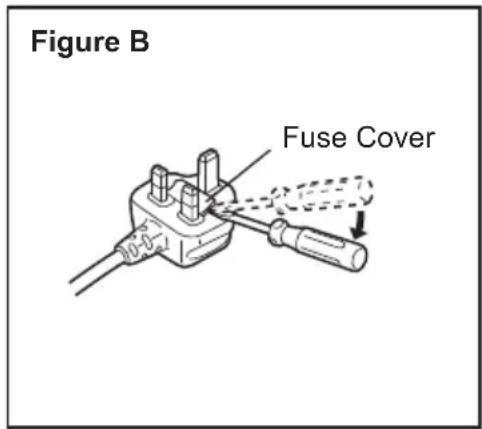
If the plug contains a removable fuse cover you must ensure that it is refitted when the fuse is replaced.
If you lose the fuse cover the plug must not be used until a replacement cover is obtained.
A replacement fuse cover can be purchased from your local Panasonic Dealer.
CAUTION:
IF THE FITTED MOULDED PLUG IS UNSUITABLE FOR THE SOCKET OUTLET IN YOUR HOME THEN THE FUSE SHOULD BE REMOVED AND THE PLUG CUT OFF AND DISPOSED OF SAFELY. THERE IS A DANGER OF SEVERE ELECTRICAL SHOCK IF THE CUT OFF PLUG IS INSERTED INTO ANY 13 AMP SOCKET.
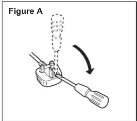
How to replace the fuse
The location of the fuse differs according to the type of AC mains plug (figures A and B).
Confirm the AC mains plug fitted and follow the instructions below. Illustrations may differ from actual AC mains plug.
Open the fuse cover with a screwdriver and replace the fuse and close or attach the fuse cover.
https://www.panasonic-powertools.eu/en/construction/documents.htm
IT
V. MANUTENZIONE
- Bewaar reserve-bits.
natural_image
Two identical hand-drawn trash bins with cross-bracing, no text or symbols presentnatural_image
Two identical diagrams of waste sorting bins with diagonal lines crossing, no text or symbols present.Lyser: Overophedning (motor)
Blinker: Overophedning (batteri)
natural_image
Two identical diagrams of waste sorting bins with diagonal lines crossing each, no text or symbols present.https://www.panasonic-powertools.eu/en/construction/documents.htm
V. VEDLIGEHOLDELSE
https://www.panasonic-powertools.eu/en/construction/documents.htm
V. SKÖTSEL
Lyser: Overopphe-ting (motor)
Blinker: Overopphe-ting (batteri)
natural_image
Two identical diagrams of waste sorting bins with diagonal lines crossing each other, no text or symbols present.Disse symbolene angir kildesortering av elektrisk og elektronisk avfall og brukte batterier.
https://www.panasonic-powertools.eu/en/construction/documents.htm
V. VEDLIKEHOLD
https://www.panasonic-powertools.eu/en/construction/documents.htm
V. HUOLTO
VIII. TEKNISET TIEDOT
natural_image
Two identical diagrams of waste sorting bins with diagonal cross lines, no text or symbols present.https://www.panasonic-powertools.eu/en/construction/documents.htm
V. BAKIM
Importer for Turkey:
Panasonic Life Solutions Elektrik Sanayi ve Ticaret Anonim Şirketi
Abdurrahmangazi Mah. Ebubekir Cad. No: 44
natural_image
Two identical hand-drawn trash bins with diagonal lines crossing each other, no text or symbols present.https://www.panasonic-powertools.eu/en/construction/documents.htm
V. KONSERWACJA
natural_image
Two identical diagrams of a trash bin with crossed-out lanes, no text or symbols present.https://www.panasonic-powertools.eu/en/construction/documents.htm
V. ÚDRŽBA
natural_image
Two identical diagrams of a trash bin with cross-bracing, no text or symbols present.https://www.panasonic-powertools.eu/en/construction/documents.htm
V. KARBANTARTÁS
For full version Operating Instructions, please refer to the web site. https://www.panasonic-powertools.eu/en/construction/documents.htm