MasterFlush MF 7220 - Toilet DOMETIC - Free user manual and instructions
Find the device manual for free MasterFlush MF 7220 DOMETIC in PDF.
User questions about MasterFlush MF 7220 DOMETIC
0 question about this device. Answer the ones you know or ask your own.
Ask a new question about this device
Download the instructions for your Toilet in PDF format for free! Find your manual MasterFlush MF 7220 - DOMETIC and take your electronic device back in hand. On this page are published all the documents necessary for the use of your device. MasterFlush MF 7220 by DOMETIC.
USER MANUAL MasterFlush MF 7220 DOMETIC
Monteringsanvising. 93
NO
Kverntoalett
Monteringsveiledning 103
FI
Sahkokaymalä
Asennusohje 113
PL
Cancer and Reproductive Harm
www.P65Warnings.ca.gov
List of figures

Copyright
© 2024 Domatic Group. The visual appearance of the contents of this manual is protected by copyright and design law. The underlying technical design and the products contained herein may be protected by design, patent or be patent pending. The trademarks mentioned in this manual belong to Domatic Sweden AB. All rights are reserved.
Service center and dealer locations Visit: www.dometic.com
Please read these instructions carefully and follow all instructions, guidelines, and warnings included in this product manual in order to ensure that you install, use, and maintain the product properly at all times. These instructions MUST stay with this product.
By using the product, you hereby confirm that you have read all instructions, guidelines, and warnings carefully and that you understand and agree to abide by the terms and conditions as set forth herein. You agree to use this product only for the intended purpose and application and in accordance with the instructions, guidelines, and warnings as set forth in this product manual as well as in accordance with all applicable laws and regulations. A failure to read and follow the instructions and warnings set forth herein may result in an injury to yourself and others, damage to your product, or damage to other property in the vicinity. This product manual, including the instructions, guidelines, and warnings, and related documentation, may be subject to changes and updates. For up-to-date product information, please visit www.dometic.com.
Contents
1 Related documents 5
2 Explanation of symbols and safety instructions 5
3 Intended use. 6
4 General information. 7
5 Specifications 8
6 Installation 9
7 Disposal 13
8 Warranty information. 13
1 Related documents

Find the quick start guide online at http://qr.dometic.com/bejZbz

Find the operating manual online at http://qr.dometic.com/beetav
2 Explanation of symbols and safety instructions
This manual has safety information and instructions to help you eliminate or reduce the risk of accidents and injuries.
2.1 Recognize safety information

This is the safety alert symbol. It is used to alert you to potential physical injury hazards. Obey all safety messages that follow this symbol to avoid possible injury or death.
2.2 Understand signal words
A signal word will identify safety messages and property damage messages, and also will indicate the degree or level of hazard seriousness.

WARNING
Indicates a hazardous situation that, if not avoided, could result in death or serious injury.
NOTICE: Used to address practices not related to physical injury.

Indicates additional information that is not related to physical injury.
2.3 Supplemental Directives
To reduce the risk of accidents and injuries, please observe the following directives before proceeding to install or service this appliance:
Read and follow all safety information and instructions.
- Read and understand these instructions before operating or servicing this product.
- Dometic recommends that a qualified marine technician or electrician install or service this product. Equipment damage, injury to personnel or death could result from improper installation. The installation must comply with all applicable local or national codes.
2.4 General safety messages

WARNING: Flooding hazard. Failure to obey the following warnings could result in death or serious injury.
- If the toilet is connected to any through-the-hull fittings, properly installed seacocks must be installed in all piping connected to through-the-hull fittings. Seacocks must be easily accessible to all users of the toilet or secondary valves fitted in hoses where they are easily accessible. All valves must be full bore valves and of marine quality. Screw-to-close gate valves are not recommended.
- If the toilet is connected to any through-the-hull fittings, all flexible hoses must be of marine sanitation quality and must be secured to any fittings (such as those at seacock, vented loop or toilet) with two stainless steel, worm-drive hose band clamps at each connection. Connections must be checked frequently for integrity.
- If the toilet rim is ever less than 8 in. (20 cm) above the highest possible waterline at any time (during any conditions of heel, load, or trim) and is connected to any through-the-hull fittings, properly positioned ventilated (vented) loops must be installed in intake (if connected to raw water) or discharge piping to prevent potential back siphonage of seawater into the boat. Vented loops must be equipped with integral check valve that permits air into line to prevent siphoning.
- If toilet uses raw water for flushing at any time, a raw water pump controlled by an automatically operating demand switch must not be installed. If the onboard water valve or any plumbing connections were to leak, the automatically operated pump would start and could flood the boat.
- Do not connect raw water flush toilet (models 7160, 7260) to an onboard pressurized water system.
- Before beginning any work on this product, be sure that all electrical power to the unit has been turned off and that the seacocks are in the closed or off position.

WARNING: Electrical shock and/or fire hazard.
Follow all local regulations for electrical installations.
NOTICE: Overfilling the holding tank can cause serious damage to the sanitation system, such as rupturing the holding tank and releasing tank contents into the bilge. To prevent this possibility, Dometic recommends using a full tank shut-down relay. The full signal from the holding tank can be generated by an optional Dometic DTM01C tank monitor or DTM04 four-level tank monitor system.

Follow all local regulations for waste tank discharge.
3 Intended use
The Macerator toilet (hereinafter referred to as toilet or product) provides an electric-flush toilet that macerates waste and pumps it either to a holding tank or other effluent storage/ disposal system, or overboard. Operated by a remote flush switch, the toilet allows the user to add water to the bowl (before or after flushing) and to flush the toilet by pushing a button. This toilet is designed for use in marine applications and is only suitable for the intended purpose and application in accordance with these instructions.
This manual provides information that is necessary for proper installation of the toilet. Poor installation and/or improper operating or maintenance will result in unsatisfactory performance and a possible failure. The manufacturer accepts no liability for any injury or damage to the product resulting from:
- Incorrect assembly or connection, including excess voltage
- Incorrect maintenance or use of spare parts other than original spare parts provided by the manufacturer
- Alterations to the product without express permission from the manufacturer
- Use for purposes other than those described in this manual
Domatic reserves the right to change product appearance and product specifications.
4 General information
The images used in this document are for reference purposes only. Components and component locations may vary according to specific product models. Measurements may vary ± 0.38 in. 10mm
4.1 Components
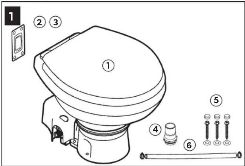
Packaging contents (Figure 1 on page 2)
| 1 Macerator toilet |
| 2 DFS-2F flush switch (standard - freshwater flush toilet) |
| 3 DFS-1F flush switch (standard - raw water flush toilet) |
| 4 1.5 in. (38 mm) discharge fitting |
| 5 Floor mounting hardware kit |
| 6 Water supply hose kit |
| Parts list1 |
| Quick start guide1 |
Not shown
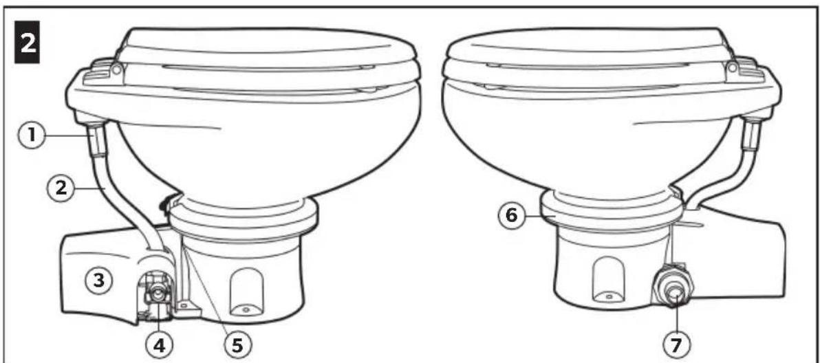
Toilet components (Figure 2 on page 2)
| 1 Rim flush check valve (freshwater toilet) or adapter (raw water model) |
| 2 Water supply hose |
| 3 Macerator pump (under plastic cover) |
| 4 Electric water valve (raw water model) |
| 5 Product ID label location |
| 6 Stainless steel compression band |
| 7 Discharge fitting |
4.2 Toilet system layouts
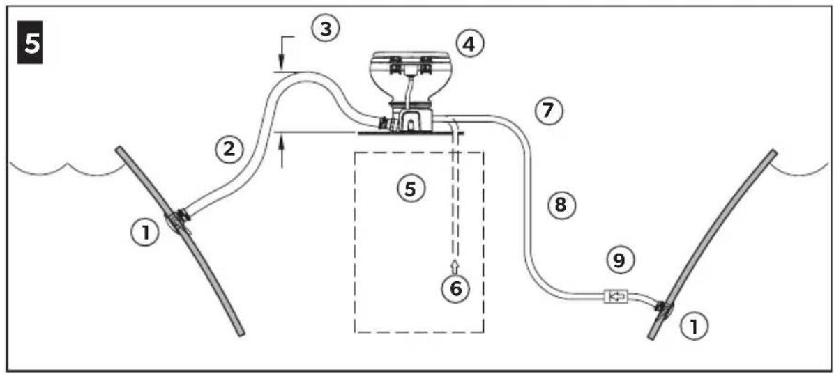
4.2.1 Above water line system
Toilet with direct overboard discharge
(Figure 5 on page 3)
| 1 Seacock |
| 2 1.0 in. (25 mm) or 1.5 in. (38 mm) ID hose |
| 3 Make loop 12.0 in. (305 mm) above the floor to retain water in the bowl |
| 4 Macerator toilet |
| 5 Freshwater supply 0.5 in. (13 mm) ID fresh water line |
| 6 From fresh water supply |
| 7 Seawater supply |
| 8 0.75 in. (19 mm) ID hose |
| 9 Check valve ensures that pump stays primed |
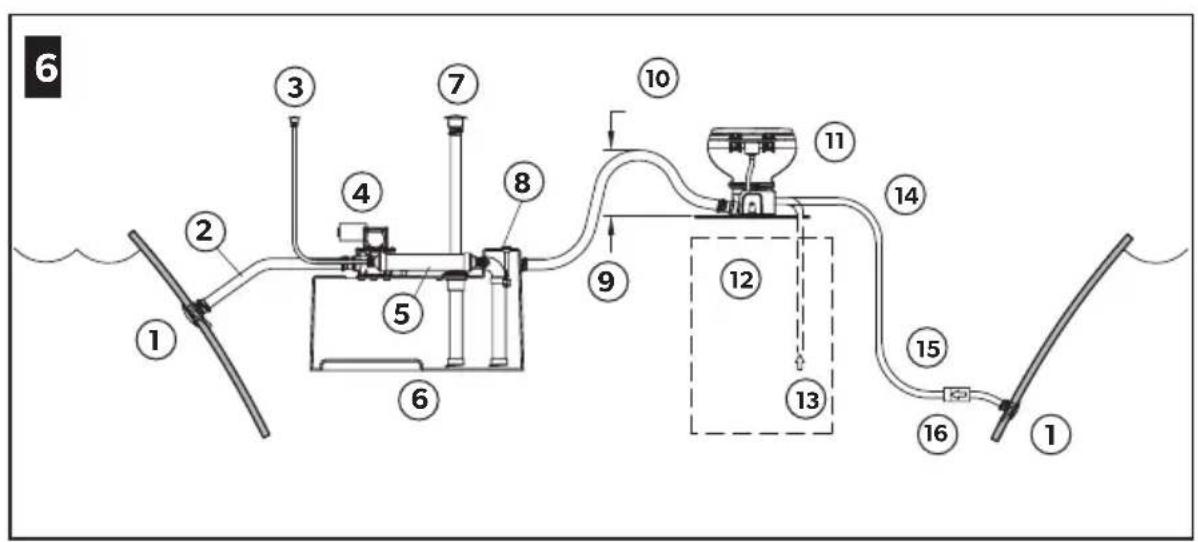
Toilet with holding tank discharge
| (Figure 6 on page 3) | |
| 1 Seacock | |
| 2 Add vented loop if holding tank is below the water line | |
| 3 Vent fitting | |
| 4 Discharge pump | |
| 5 Vent filter | |
| 6 Holding tank (cut-away view) | |
| 7 Deck discharge | |
| 8 Optional full tank level float | |
| 9 1.0 in. (25 mm) or 1.5 in. (38 mm) ID hose | |
| 10 Make loop 12.0 in. (305 mm) above the floor to retain water in the bowl | |
| 11 Macerator toilet | |
| 12 Freshwater supply 0.5 in. (13 mm) ID fresh water line | |
| 13 From fresh water supply | |
| 14 Seawater supply | |
| 15 0.75 in. (19 mm) ID hose | |
| 16 Check valve ensures that pump stays primed |
4.2.2 Below water line system
Toilet with direct overboard discharge
(Figure 7 on page 3)
1 Seacock
21.0 in. (25 mm) or 1.5 in. (38 mm) vented loop
3 Vent fitting
41.0 in. (25 mm) or 1.5 in. (38 mm) ID hose
5 Macerator toilet
6 Freshwater supply
70.5 in. (13 mm) ID fresh water line
8 Seawater supply
90.75 in. (19 mm) ID hose
10.75 in. (19 mm) vented loop with check valve
11 Vent fitting
12 8.0 in. (203 mm) minimum
13 Maximum heel
14 Waterline range
15 Static
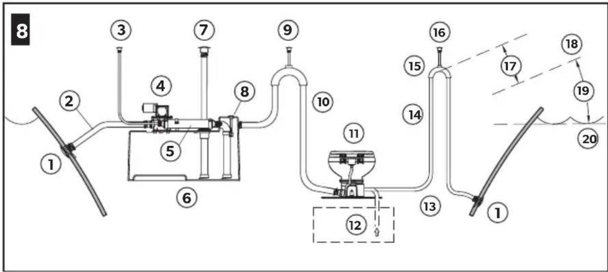
Toilet with holding tank discharge
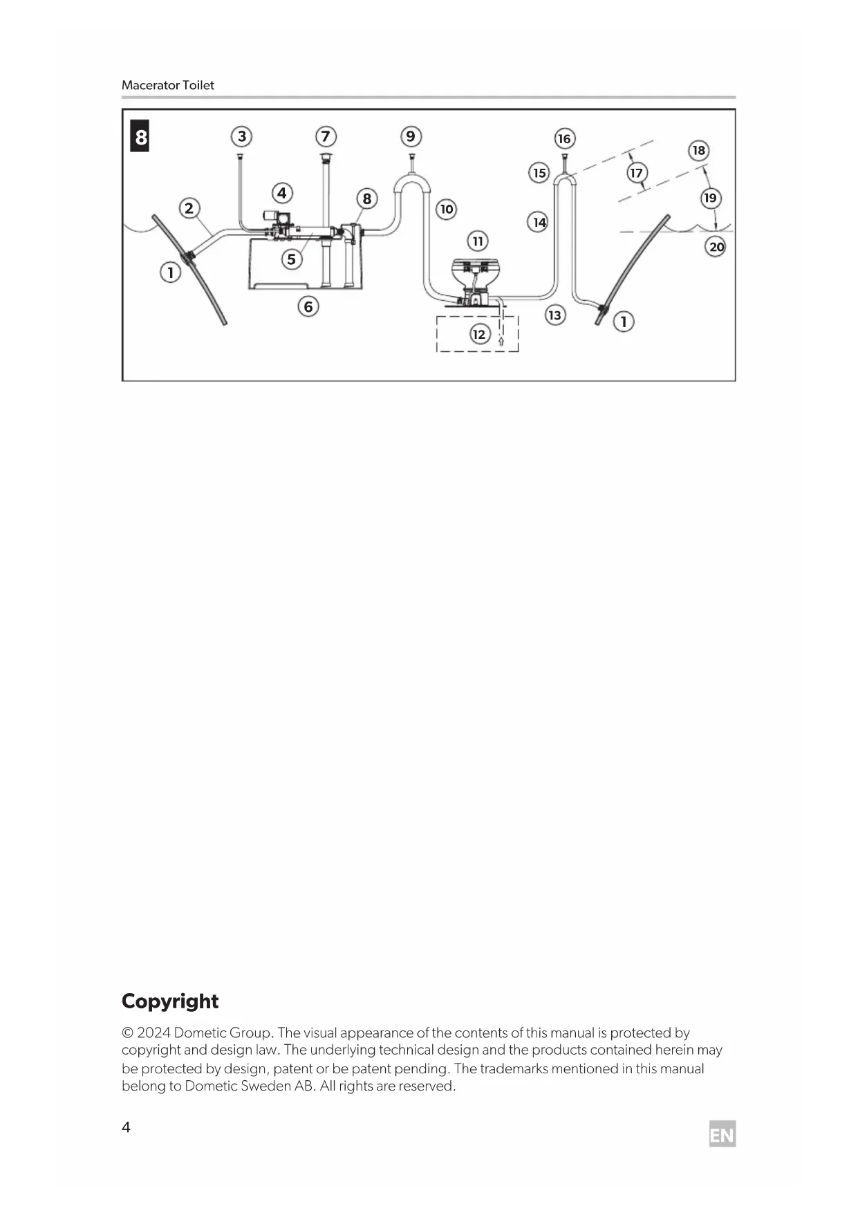
(Figure 8 on page 4)
1 Seacock
2 Add vented loop if the holding tank is below the waterline
3 Vent fitting
4 Discharge pump
5 Vent filter
6 Holding tank (cut-away view)
7 Deck discharge
8 Optional full tank level float
9 Vent fitting
101.0 in. (25 mm) or 1.5 in. (38 mm) ID hose
11 Macerator toilet
12 Freshwater supply 0.5 in. (13 mm) ID fresh water line
13 Seawater supply
140,75 in. (19 mm) ID hose
150.75 in. (19 mm) vented loop with check valve
16 Vent fitting
17 8,0 in. (203 mm) minimum
18 Maximum heel
19 Waterline range
20 Static
5 Specifications
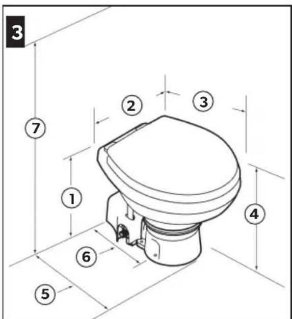
5.1 Dimensions
7120, 7160 (standard bowl)
(Figure 3 on page 2)
1 14.8 in. (375 mm)
215.0 in. (381 mm)
319.0 in. (483 mm)
413.8 in. (349 mm) seat height
513.8 in. (349 mm)
6 10.0 in. (254 mm)
728.75 in. (730 mm) seat lid up
7220, 7260 (compact marine bowl)
(Figure 3 on page 2)
1 13.3 in. (337 mm)
214.5 in. (368 mm)
318.8 in. (476 mm)
4 12.3 in. (311 mm) seat height
513.8 in. (349 mm)
6 10.0 in. (254 mm)
7 26.3 in. (667 mm) seat lid up
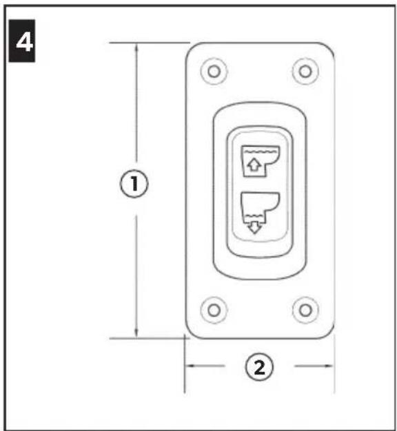
Dometic flush switch panel
(Figure 4 on page 2)
13.25 in. (83 mm)
21.625 in. (41 mm)
5.2 Materials
| Toilet Vitreous ceramic | |
| Toilet base Polypropylene | |
| Domatic flush switch panel | Polystyrene (DFS-1F or DFS-2F); or powder-coated aluminum (DFST) |
5.3 Minimum System Requirements
| Electrical Power draw 20 amps /12 VDC; 10 amps /24 VDC | ||
| Circuit breaker | 25 amps /12 VDC; 15 amps /24 VDC | |
| Wiring¹ | 12 gauge Up to 25 ft (7.6 m) total circuit | |
| Water Supply | Fitting size Supply hose ID | 0.5 in. NPT - fresh water flush toilet |
| 0.75 in. ID - raw water flush toilet | ||
| Flow rate 2.0 gpm /7.6 lpm minimum - fresh water flush | ||
| Discharge | Inside diameter | 1.5 in. (38 mm) or 1.0 in. (25 mm) |
| Horizontal run² | 40 ft (12.2 m) maximum | |
| Vertical run² | 4 ft (1.2 m) maximum | |
Consult ABYC guidelines for additional information.
2 Horizontal and vertical run distances are not cumulative. Check for adequate discharge flow if installation nears one of these limits.
6 Installation
Determine whether the water supply to the toilet will be fresh water or sea water, above or below the vessel's water line, and then follow the appropriate instructions for the installation.
6.1 Above water line system
For layout details, see "Above water line system" on page 7.
The following information is important:
- The toilet bowl rim must be a minimum of 8.0 in. (203 mm) above the highest possible water line at full heel.
- Vented loops must be a minimum of 8.0 in. (203 mm) above the highest possible water line at full heel. For optimum toilet operation, install the vented loop as close to 8.0 in. (203 mm) height as possible.
- Place vented loops near the center of the boat to minimize fluctuation of the water line height.
Maximum seawater pump lift is 4 ft (1.2m)
Maximum discharge head is 4 ft. (1.2m)
6.2 Below water line system
For layout details, see "Below water line system" on page 8.
The following information is important:
- The 0.75 in. (19 mm) vented loop must use either a duckbill valve or electric normally-open solenoid valve.
- Vented loops must be a minimum of 8.0 in. (203 mm) above the highest possible water line at full heel. For optimum toilet operation, install the vented loop as close to 8.0 in. (203 mm) height as possible.
- Vented loops should not exceed a maximum of 2 ft (0.6 m) above the water line.
- Place vented loops near the center of the boat to minimize fluctuation of the water line height.
Maximum seawater pump lift is 4 ft (1.2m)
Maximum discharge head is 4 ft. (1.2m)
6.3 Inlet plumbing

WARNING: Flooding hazard.
Do not connect sea water flush toilet inlet line to a pressurized freshwater system. This will result in a continuously running freshwater pump, which can possibly overflow the toilet bowl, and flood the boat. Failure to obey this warning could result in death or serious injury.

WARNING: Contaminated water hazard.
Do not connect sea water flush toilet inlet line to an onboard potable water system in any way. This can cause contamination of the potable water system. If fresh water is desired, purchase the freshwater-flush version of the toilet, or provide a separate freshwater tank that supplies water only to the toilet. Failure to obey this warning could result in death or serious injury.

Be sure to install a vented loop that will not prevent the required water flow to the toilet when it is flushed. An electric solenoid type is recommended.
6.3.1 Sea water flush models
-
Install the seacock and inlet water line (not supplied).
-
Use a 3/4 in. (19 mm) full-flow seacock and a 3/4 in. (19 mm) ID flexible hose. Follow the seacock manufacturer's installation instructions.
- Make sure the inlet seacock is below the sea water line at all times, during all conditions of full heel.
- Make sure all inlet hose connections have no sharp bends or restrictions.
- Use two stainless steel hose clamps at each connection.
- Provide hose support every 3 ft (0.9m) along the inlet hose run to limit movement.
-
Keep hose runs as short as possible. Eliminate sags or low spots that may hinder flow.
-
Install the water inlet strainer (not supplied).
-A 100-mesh strainer is recommended between the inlet seacock and the sea water flush toilet.
- Install the inlet check valve for above-waterline installations (not supplied).
-A check valve should be installed in the inlet supply line to ensure the toilet's sea water pump stays primed between flushes.
- The check valve should be located as close as possible to the inlet seacock. See "Above water line system" on page 7.
-
Install a vented loop (not supplied).
-
If the toilet rim will ever be less than 8.0 in. (203 mm) above the highest possible waterline at any point of heel, trim or load, then a 3/4 in. (19 mm) vented loop must be installed in the inlet hose between the inlet seacock and the toilet. See "Below water line system" on page 8.
- The vented loop must be positioned a minimum of 8.0 in. (203 mm) above highest possible waterline during all conditions of heel, trim or load.
6.3.5 Freshwater flush models
-
Install the inlet water line (not supplied).
-
Use a 0.5 in. (13 mm) ID flexible hose with 1/2 in. NPT fitting connects to the toilet water valve.
-
Install a shut-off valve in the inlet line (not supplied).
-
For toilet cleaning and maintenance.
6.4 Outlet plumbing
Sea water flush models only.
-
Install the seacock and outlet sanitation hose (not supplied).
-
Use a 1.0 in. (25 mm) or 1.5 in. (38 mm) full-flow seacock and flexible hose to route the waste to a holding tank with a discharge pump, or route directly overboard. Follow the seacock manufacturer's instructions.
- Make sure the waste outlet seacock is both aft and higher than the water inlet seacock.
- Outlet plumbing should have no sharp bends or restrictions.
- Use two stainless steel hose clamps at each connection.
- Provide support along entire hose run to limit movement and side-loading on connections.
-
Keep hose runs as short as possible. Eliminate sags or low spots that may hinder the flow.
-
Install the discharge hose loop near the toilet (not supplied).
-
To retain water in toilet bowl, make a 12.0 in. (300 mm) high loop in the discharge line as near to the toilet as
possible. See "Above water line system" on page 7.
-
Install a vented loop (not supplied).
-
For recommended locations of discharge vented loops connected to system components that are below the water line or may be less than 8.0 in. (203 mm) above the highest possible water line at full heel, see Figure 7 and Figure 8.
-
Vented loops must be positioned a minimum of 8.0 in. (203 mm) above highest possible water line at full heel.
6.5 Toilet and flush switch
- Carefully unpack the toilet, water supply hose, discharge fitting, and hardware). See Figure 1.
- Place the toilet in the desired location on the floor. If necessary, rotate the toilet so that macerator pump housing does not interfere with walls, or so that it accommodates the intended plumbing layout. See Figure 2.
- Confirm adequate clearance is available for the plumbing connections, and also the seat and lid in raised position.
- Mark the floor where the toilet will be installed.
- (Optional) If the macerator pump and base must be positioned at an angle so that toilet bowl does not face the wrong direction, rotate the upper bowl to the proper position.
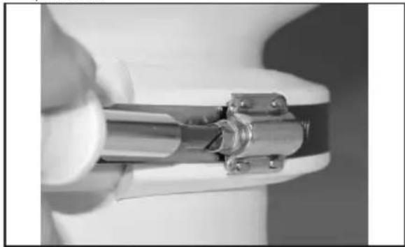
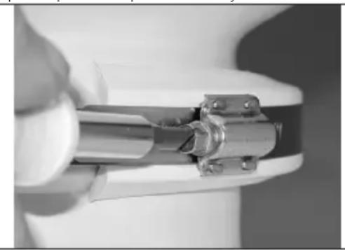
9 Loosening the compression band
a. Loosen the compression band just enough to slip down past the lower plastic clamp.
10 Removing the plastic clamps
b. Remove the upper and lower plastic clamps.
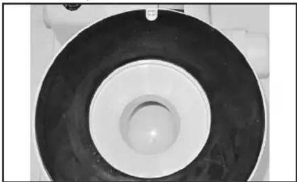
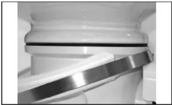
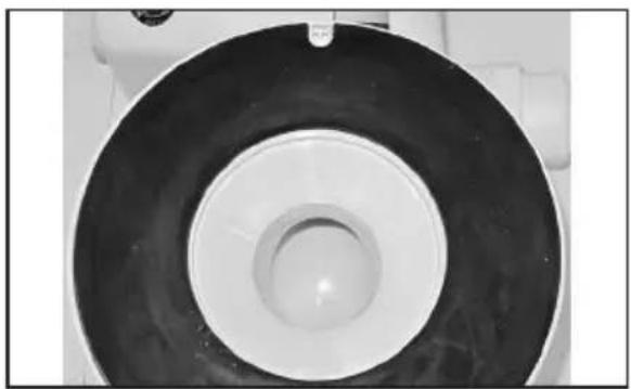
11 Positioning the gasket
c. Lift the bowl. Make sure the notch in the black rubber gasket sits around the shallow pin on the toilet base and remains centered between the bowl and base.
d. Rotate the bowl to the desired position, then set it down on gasket.
e. Re-position the plastic clamps and compression band between the upper bowl and base.
f. Join the clamps together at the front of the toilet bowl. There will be a space between the clamps behind the bowl.
g. With the compression band screw positioned on a clamp (not in gap between clamps) tighten the compression band to 65 in. Ibs (7.3 N-m).
- Connect the water supply hose between the check valve or adapter and water valve (freshwater flush model) or the water pump (sea water flush model) on the base. See Figure 2.
a. Cut the supply hose to a length that will not kink when connected.
b. Remove the plastic cover from the pump. See Figure 2.
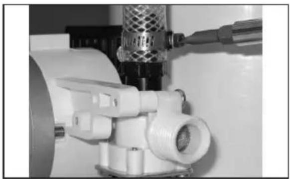
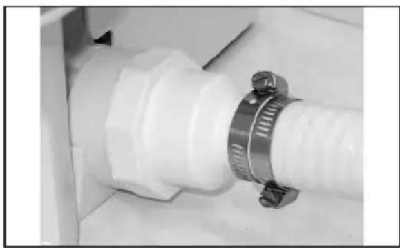
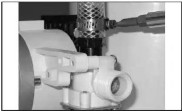
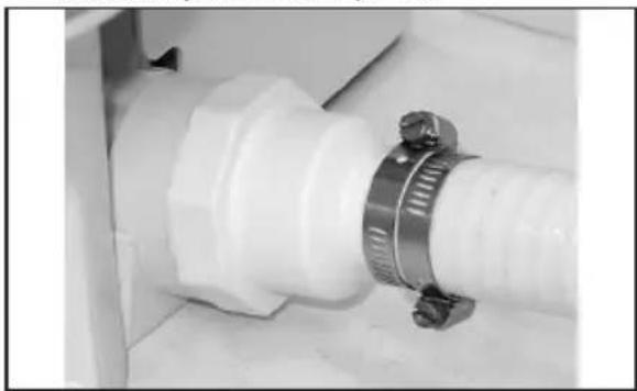
12 Tightening the hose clamp
c. Use the hose clamp to secure the hose to water valve (freshwater model) or pump (sea water model) barbed fitting.
d. Place the loose end of the supply hose up through the hole of the plastic cover.
e. Lower and fit the cover to the macerator pump.
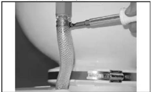
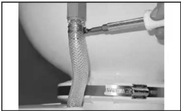
13 Connecting the water supply hose
f. Connect the water supply hose to the rim flush check valve with the hose clamp.
- Plan the electrical, water supply, and discharge plumbing according to appropriate toilet system layout. See "Toilet system layouts" on page 7.
- Create access holes for the plumbing and electrical supplies to the toilet.
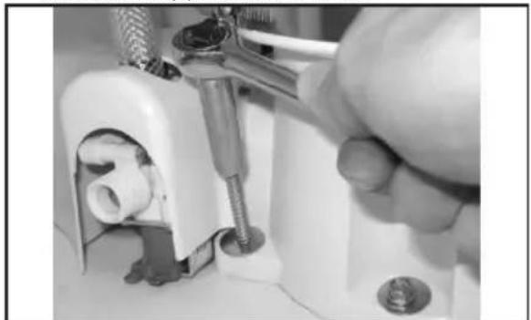
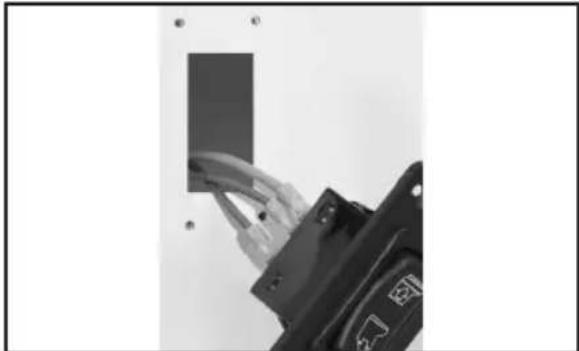
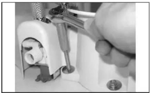
14 Fastening the toilet to the floor
- Place the toilet in its final location and fasten it to floor with hex head fasteners and washers at the sides and rear of the base.
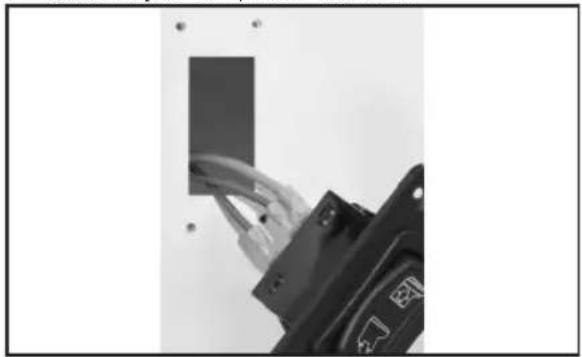
- Plan the flush switch location so that the electrical connections and wires cannot get wet.
- Use the switch template (packed separately) to mark the location of the fasteners and switch access hole.
15 Switch access hole
- Cut out the switch access hole.
- Turn off the electrical power.
-
Route the stranded copper positive wire (gauge per ABYC standards) from the circuit breaker or fuse to the switch access hole.
-
If the toilet system includes a DTM series tank monitor system, see "Toilet system with tank monitor and shut-down relay" on page 13.
Refer to the wiring diagram on the reverse side of the parts list.
- Route the red wire from the macerator pump to the switch access hole.
- Route the wire from the switch access hole to the electric water valve at bottom of the toilet (freshwater model).
- Connect the wires according to the diagram with the appropriate spade connectors.
- Attach the flush switch to the wall with screws provided.
- Connect the ground wires from the macerator pump and the electric water valve (freshwater models only) to the vessel's electrical ground wiring according to the wiring diagram. Provide extra wire at the toilet so that the toilet can easily be removed from the floor for servicing.
- Route the vessel's water supply and the discharge plumbing to the toilet. See "Toilet system layouts" on page 7.
16 Hose clamps on discharge hose
- Securely connect all the discharge hoses with two stainless steel hose clamps with the screws positioned 180^ opposite each other.
- Lubricate the fittings and the hoses with silicone grease to make the hose connection easier.
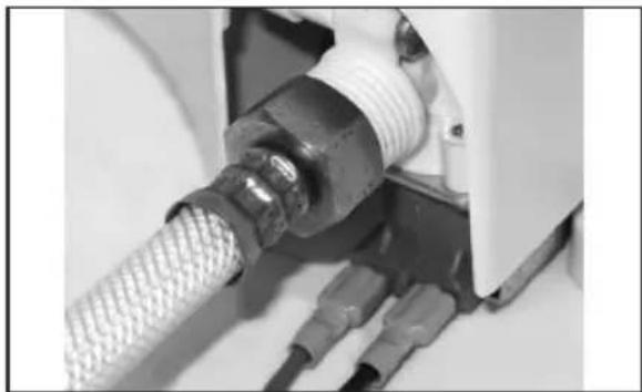
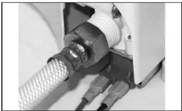
17 Connecting the water supply
- For a freshwater toilet, connect the water supply with 0.5 in. NPT fitting.
NOTICE: Do not operate the toilet with the water supply turned off. Damage to the internal components may occur.
- For a sea water flush model, open the water supply and discharge the seacocks.
- For a freshwater model, turn on water supply.
- Check for water leaks at all connections.
- Turn on electrical power to toilet.
- Press the flush switch and check for leaks. If a leak occurs, tighten the connection.
- Attach the plastic covers to the floor mounting fasteners.
6.6 Toilet system with tank monitor and shut-down relay
Dometic MasterFlush toilets operate with Dometic DTM tank monitor systems (available separately) to shut down electrical power to the
toilet when the holding tank is full. This prevents overfilling the holding tank. Refer to the toilet system wiring diagram on the parts list.
- Route the input power wire from full tank relay of the DTM panel to the flush switch location.
- Follow the flush switch installation instructions on page 11 beginning at step 10.
7 Disposal
Place the packaging material in the appropriate recycling waste bins, whenever possible. Consult a local recycling center or specialist dealer for details about how to dispose of the product in accordance with all applicable national and local regulations.
8 Warranty information
Refer to the sections below for information about warranty and warranty support in the US, Canada, and all other regions.
8.1 United States and Canada
LIMITED WARRANTY AVAILABLE AT DOMETIC. COM/EN-US/TERMS-AND-CONDITIONS-CONSUMER/WARRANTY.
IF YOU HAVE QUESTIONS, OR TO OBTAIN A COPY OF THE LIMITED WARRANTY FREE OF CHARGE, CONTACT:
DOMETIC CORPORATION
SANITATION CUSTOMER SUPPORT CENTER
13128 STATE ROUTE 226
BIG PRAIRIE, OHIO, USA 44611
1-800-321-9886
8.2 Asia-Pacific (APAC) countries
If the product does not work as it should, please contact your retailer or the manufacturer's branch in your country (see the back of this instruction manual for the web addresses to locate your region or retailer). The warranty applicable to your product is ONE year.
For repair and warranty processing, please include the following documents when you send in the device:
A copy of the receipt with purchasing date
- A reason for the claim or description of the fault
8.2.1 Australia only
Our goods come with guarantees that cannot be excluded under the Australian Consumer Law. You are entitled to a replacement or refund for a major failure and for compensation for any other reasonably foreseeable loss or damage. You are also entitled to have the goods repaired or replaced if the goods fail to be of acceptable quality and the failure does not amount to a major failure.
8.2.2 New Zealand only
This warranty policy is subject to the conditions and guarantees which are mandatory as implied by the Consumer Guarantees Act 1993(NZ).
8.2.3 All other regions
The statutory warranty period applies. If the product is defective, please contact the manufacturer's branch in your region or your retailer (see the back of this instruction manual for the web addresses to locate your region or retailer).
For repair and warranty processing, please include the following documents when you send in the device:
A copy of the receipt with purchasing date
- A reason for the claim or description of the fault
Note that self-repair or nonprofessional repair can have safety consequences and might void the warranty.
Visite: www.dometic.com.
9 De compressieband losmake
8.2 Azie-Pacific (APAC) landen
slangen for at forhindre tvmning.
8.2.2 Kun New Zealand
Denne garantipolitikken er unterlagt betingelserne og garanterer, som er obligatoriske som indeholdt i forbrugergarantiloven 1993(NZ).
8.2.3 Alle andre regioner
12 Dra at slangkämman
Dometic bryterpanel for spying
(Figur 4 pà side 2)
183 mm (3,25 tommer)
24] mm (1,625 tommer)
5.2 Materialer
Dometic bryterpanel for spying
Polystyren (DFS-1F)
eller DFS-2F);Eller
pulverlakkert aluminium (DFST)
5.3 Minimum systemkrav
KomnoHeHTbI yHHTa3a (Pnc. 2 Ha cTp. 2)
6.3 BnyckHOI Tpy6oNpOBoD

ПЕДУПЕХДЕНЕ: Рuck 3aToNneHnA.
3anpeaetcnoDCoeHNrBNIHIO
POnaHmOPCKoB OBOI DnT TuaNeta
KHaOpHO6OpTOBOCnCTMe
POnaHn PpeCHO BObI.3To npNBedeT
KNoCTOHHOMy PpOKaUNBaHNIO PpeCHO
BObIMoXeTBbl3BaTbpepenONHeHne
YaWN yHHTa3aN 3aTOnPiHne CyDHa.
Heco6nODeHne 3TOro npEynpexJeHn
MOxET nPnBeCTN K CMEPTN IN
cepbe3HOITpaBMe.

IPEyIPEXDEHNE:OnachocTb 3aqr3HeHHBObl.
3anpeauotcno6bI NOKNUOeHn HINNIPOaH MOpCKOBoBdTyneta K6opTOBO CNCTeMe NtBeBOBdo. 3TO MOXET PnBecTN K3aP83HeHIO CNTEmbl NTbeBOBdo.Ecn dNraCnBa
6ydet NcnoB3OBaTbCnpeChnBaD, Heo6xOIMO npNo6peCTn CneuHaNbHyOp BepCNIO TuaneTa, npeHa3NaeHHyO DnI NCNOB3OBAHN IpeCHOBDoI, IIn6o yCTaHOBHTb OTdEhHyO EMKOCtB Cnpesho BOoH NCKIOUHTeNBHO DnI NOaHn BObl TuaNET. Heco6nIOJeHne 3TOO npDeynpeXeHnMoXeT npNBecTN K CMEPTN INN cepBe3HO TpaBMe.

O6raTeNbHO yCTaHOBHTe
BeHTnInpyEmoe KOneHo, KOTOpoe
He 6yET npenrTCTBOBaTb NOaYe
Heo6xOIMoro KOINueCTBa BObl B Tyanet
PnCnBE. PekomeHnyETcNcNoIb3OBaTb
3NeKTPomarHnTHbI TnI.
- YCTaHOBNTe KINrCTOH N BbInyCKHO KaHaJIIN3aUNHOHHbI WnAHT (He BXoDIT B KOMNKeT NOCTaBKn).
-IVcnoB3yIte NOHONOTOHbIN KnHrCToH 25 MM (1,0IOHMOB) INN 38 MM (1,5IOHMOB) INI6KNI UNaHr IIN TpaHCnOpTnPOBKN CTOKOB B HAKONITeMbHy IO NCItePHy C NOMOuBIO Haocca CNBa, IN6O npOnoxTe
Tpy6oNpOBOIDIINBACTOKOBHapmyo 3a60pt.BbInonHnTe INHCTpykUIN npOn3BODNTeI NOYCTAHOBKE KHNCTOHa.
-yeBbIyCKHO KINrCTOH paCNoTOXeH B KOpMOBOY aCTN BbIe yPOBnBnCYCKHOrO KINrCTOHa.
-BbIyckHOITpy6oNpOBOHeIOnXeH NMeTbOCTpbIXKpaEBINNOrgaHueHIn npOXoDMOCNT.
-IVcnoIb3yIte IBaXOMyTa H3HepXaBeIOSe CTaNHa KaXdOM COeINHeHN UJNaHra.
-YCTaHOBHTe ONOpbI NO BCeINHe ⅢNaHra, YTO6bl OpaHnUHTbeO npemMeueHne I 6OKOByIO Hapy3KyHa CoeINHeHn.
-ДиHA yAcTkoB шнангdoJnxHa 6bItb MInHMaJIbHO.NcTpAnHe npOBncaHn Hn3Kne yAcTK, KOTOpBe MOrYT npEnrTCTBOBaT NOTOKy.
- YctaHOBNTe KONEHO CINNBHOI WIIaHra PRAOM CTyaneTOM (HE BXODNT B KOMNIEKT NOCTaBKN).
-уTo6blIOnDiepXnBaTb yPoBeHbBObl B YAWe yHnTa3a, CdenaIte KOneHO BlicOTOn 300 MM (12,OIOHMOB) BINHH CNBa KaK MoXHo 6nHexe KyHnTa3y. CM. «CnCTema BblSe BaTepePnHHN» Ha cTp. 169.
- YctaHOBNTe BeHTnnpyEmoe KoneHo (He BXoINT B KOMPNIeKT NOCTaBKn).
-Cm. peKOMeHdauu no paCnoIoxeHHo BeHTnnpyemoro KOneHa cNBA, NOIKNoUeyHrO K KomNoHeHTaM CnCTeMbI, paCnoIoxeHHbIM Hxke BaTePnHInn, NIOBO Ha BbICote Mehee 203 MM (8,OIOHMOB) NaMaKcImaNbHbIM yPoBHeM BaTePnHInn npi npedeHbHom KpeHe, Ha Pnc.7 n Pnc.8.
-Bentnnpyemoe Koneho dOnxHo
pacnoaratbcre He MeHee Yem Ha 203 MM
(8,OIOHMOB) Bblse MaKcMaNbHO
BO3MOXHO yPOBHa BaTePnHH
pni npedeHbHom KpeHe.
6.5 YHnTa3 n nepeKJIIOuATEIb cINBa
- OctopoxHo paCnakyIte yHHTa3, IuaHr IoDaH N BOIbI, CINBHOJ cHITINr IN KpeNex). CM.Pnc.1.
- Pa3MeCTIe yHHTa3 B Tpe6yemOM MeCTe Ha NOny. PpN Heo6xOAnMoCTn NOBepHNTe yHHTa3, TaK YTo6bl KOpNyc Hacoca
H3MeIbUHTeJI He yInpaIcB CTeHKn HIN YTO6bl Bnncatb ERO B rOTOBYIO CXemy paCnoJoxehn Tpy6oNpOBOIoB.CM.Pnc.2.
3.ПоДТВЕРДИТЕHAHINUHNEIOCTaTOUHORO CBO6ODHOrO pOcTpaHCTBa DnA COeDInHeHn Tpy6OpOBoDOb,aTakXeIdNcUdEhBn KpbIuKNBPODHrOMNpOKeHnN.
4. OTMeTbTe MeCTO dIy yCTaHOBKn yHHTa3a Ha NONY.
5. (OnuohbHo) Ecnn Hacoc n3MeIbHTe I OCHOBHHeo6xOIMO yCTaHOBt b NODyTOM, TaK yTo6bIyAaYyHNTa3a He 6bIa NOBepHyTa B HeBepHom HanpaBneHIn, pa3BepHTe BepXHIOU yaWy.
9 Ocna6nneHne 6aHaXHOH neHTbl
a. Ocna6bTe 6aHdaxHyIO neHTy poBHO HAcToIbKO, HAcKoIbKO HeO6XoIMO, UTO6bl CnYCTNTb NeHTy HnXe HnXHeRo INaCTMaCCOBOrO XOMyTa.

10 CHaTHe IInactMaCCOBbIX XOMyTOB
b. CHIMITE BepxHne HnXHne nINaCTMaCCOBbie XOMyTbl.
11 PaonoloxeHne npoknaidkn
c.ПОДHIMMTEчу.Y6eIITecb, YTO BbIeMKaBчepHOJpe3INHOBoi npOKlaKe HAdetaHa He6OJIbwoi NaeuC OCHOBAHNyHNTa3a N OTUeHTpnpOBaHa MExdy ChSeN OCHOBAHNEM.
d. Pa3BepHnTe yaIy B Tpe6yemoe nOIOXeHne, 3aTeM yCTaHOBnTe Ha npOKnAky.
e. NpeMeCTIte InactMaccOBbie XOMyTbI 6aHdaxHyIOJeHTy MExy BepxHei yAWeiN OCHOBAHNEM.
f. CoeINHInTe XOMYtB Ipyr C pyrrom B npeDHeu qactn yaun yHHTa3a. MexyXOMyTAMN NO3aHn yauH 6ydet CBO6OdHOe npocpaHCTBO.
g.CBHTOM 6aHdaxHOJneHtbl, paCNOIOXeHHbIM Ha XOMyTe (He B 3a3OpE MEXdy XOMyTaMn), 3aTHNTE 6aHdaxHyIO NeHTY MOMHTOM 7,3 H-M (65 cyHTO-DIOHMOB).
6.ПодсоeHnTeшнгпаду BOdI MExdy O6paTHbIM KnaHOM IINI nepeXoDHnKOM N BOdIbIM KnaHOM (MOeIbI ppeCHOBbI) INI BOraHbIM HacocOM (MOeIbI dIg MOpCKoI BObl) BOCHOBAHn.Cm.Pnc.2.
a. Otpexbte ⅢnHr nOdaun Ha HyxHyo dnnHy, TaK yTO6bl OH He nepekpyuBaNCB NODKnIOueHHOM nOIOXeHN.
b. CHIMITE pIaTMacCOByIO KpbIiKy c HAcOca.CM.PnC.2.
12 3aTkKaXOMyTaUNaHra
c.ИспоьзуITExOMyTшанг,чTO6bI 3akpeNTbшангHa STTyuepe BOJHOrO KnaHnA(MOeJIbДЯпpeCHOI BObl) IINHacOce(MOeJIbДЯМOPCKOIBOdbI).
d. IomeCTte ⅢnAHTnoaun CBO6oHbIM KOHcOM BBepx B OTBepCTne B nactMaCCOBOn KpbIuKe.
e. Onyctnte n yctaHOBNTe KpbIHKy Ha HAcOC N3MeNbHTenTn.
13 PoiKIOHHe IHaIHa IOnaHy BObl
f. POncoeHNHTe 7nAHT NOaH NBOBk O6paTHOMy KnaHaHy CnBaNPOO6OKOM C NOMoubXOMyTa.
7.CoCTaBbTe PnHa NJIeKTpNueCKOINCTeMbI, CNCTeMbI BOIOChA6XeHIN CnIBa B COOTBeTcTBnC Tpe6OBaHnMn K paONOnOKeHNIO KOMNOHeHTOB.CM. 《CxemblCNCTeMbITyaNETa》Ha ctp.169.
8. CdaenaiTe OKoWKn dnnIocTyna K Tpy6oNpOBoDam n 3neKtpoNpOBoDke Tyaneta.
14 KpennneHne yHnTa3a K nony
9.YCTaHOBInTe yHnTa3 B OKOHyATenbHoe IIOXeHne n 3aKpeNITE erO K NOy C NOMOUBIO KpeNEXHBIX 3IneMENTOB C IeCTINrpaHHoI rONOBKOu I uai6 No 6okam IN IO3aDN OCHOBAHN.
10. OnpeDenItecb pacnoOnxHneM nepeKnIOyateTn CnBa, TaK YTO6b I Ha 3NeKTPnueckne CoeINHeNn IN PPOBda He IonoaDana BODa.
11. VcnoNb3yIte w6nOH nepeKnIOuataTEn (ynakOBaHHbI OTenbHO),YTO6bl OTMeNTb paCNOxHHeK pENNEHm N OKoUka DnA DOCTyNA K nepeKnIOuATenIO.
15 OkoKIO dno doctyna K nepeknioauteiHO
- Bbipexbte okoIIO dIaocTyna KnepeknioateNIO.
- Otkliouyte 3neKtpoNTaHne.
- PpONoXnTe MHOrOxNbHbI NonoXnTeNbHbIMeHbI npOBoD (Kan6p No cTaHapTaM ABYC)OT aBtOMaTnueckOro BbIKIOuATenI INI ppeOxpaHnteR K OKoUkY dIra DOCTyNa K nepeKnOuAteIO.
-ECnB CnCTeMy TyaIeta BxOaNT FyHKuIM MOHITOpINHa UInCTepHbI cepINDTM, cm. «CnCTema TyaIeta C MOHITOpINrOM UInCTepHbI IN pene OTKJIIOUeHINRA» Ha cTp. 176.
Cm. 3neKtpnueckyio cxemy Ha o6paTHoI CTopoHc CnNcKa 3aHuaCTeN.
- ПрпожиTe красньnpовд OT hacocan 3MeIbЧИТЯ K OkOШКу ДЯdoCTуna KpekeKIOUaTeNIO.
16.ПронохиTe npOBOD OT OKOUSAДЯ DOCTyna KпepeкнIOчATEENIO KэлeКТрИчecKOMY BOДHOMY KПанHy B HIXHHeNЧАNTyHNTa3a (Mодь дЯ псECHОВОbl).
17.ПОДСоЕДНИТЕ ПОВОДA B COOTBETCTBиN CO CXEMO N NOMOUIIO COOTBETCTBYOUHIX PLOCKNX KOHTAKTOB. - 3akpenite nepeknoyateNBcNBA BnHTamK CTeHe.
19.ПодcoeINHITe npOBaMaMaccbIOT HacocaN3MeNbUHTeNn3NeKTPnueCKOBOBdHOroKnanaHa(TOnbKOMOeNnDnIpceHOBd)K KOHTpy 3a3EmnEHHcYdHB COOTBeTCTBnN Co CXemO.N.O6ecneybTe3anacnpOBaYTuaneTa,TakTObI TuanETMOxHO6blNO NERKOOTCOeINHITbOTnONAnO6CnykBaHN. - Пponoxinte Tpy6o npoBoDb BOOCha6xeHnI cNIBa cyHa K yHnTa3y.CM.《Cxembl CnCTeMbTyaneTa》Ha cTp.169.
16 XomytbHa HuaHre CnBa
- HAdexHNO NOcOeHNHTe BCE WNaHr CnBa DByMxOMyTaMn I3 HePxaBeIOUeI CTaIN C NOMoUbIO BnHTOB, paCNoONxeHHbIX NoD yNOM 180dpyr HAnpOTNB dpyra.
22.CmaXbTeΦnTHHnN UNaHnC NOMOsbIO CNINKOHOBOmCA3KN, YTO6bI ynpocHTb NOKIOUeHne UNaHROB.
17 PoiKIOUoyHHe K CNTeMe BOOCHa6XeHnA
23.ДЯ moDeEN C npecHOB BOOJ NOcOeHnTe BOOCha6xehne C nOMoUbO φntnHa NPT 0,5IOHMOB.
3AMEUAHNE: He nCNoB3yIe TyaJIeT COTKIOUeHHbIM BOIOCha6XeHEm. 3TO
MOXET PnBcCTN K NOBpeKDeHIO BHyTpeHHIX KOMHOHETOB.
24.ДЯ moIeNeI c MOpCKoI BOIo OTKpoIte NOdauy BObl N CneIte KINrCTOHbl.
25.ДЯ moeENI C npeCHOB BOO BKNIOHTe NOaHy BObl.
26.Поверпгетерметуновсь CBex COeINHeHn.
27. BkIIOUHTe 3JIeKTpOnITaHne TyaIeTa.
28. Haxmnte Ha nepeknioateb cnBa n npobepbTe hannue yteek. B cnyuae yteKN 3aTnHTe coednHeHne.
29.ПиносоeINHITe ПпаCTмСССБье КрышКНHaONbHbIM KpeNexHbIM 3JIeMeHTaM.
6.6 Cnctema TyaIeTa c MOHITOPHHROM nCTepHbI n pene OTKIOUOeHn
TyaneTb Dometic MasterFlush nCnonb3yIOT cnCTemy MOHITOPINHa DometicDTM (noCTaBnAETcO TdEINbHO) dR OTKIOUeHNr 3JIeKTPoPHTAHNr pN 3aONHeHN cTOHON YIcTePbI. 3TO IO3BOJAE T36ExaTb ee nepenBa.CM. cxemy npOBOKn CnCTeMb Tyaneta B nepeyne 3aunacteN.
- ПюожиTe BxOДнО npOBOD nITaHn OТ рeNe 3anONHeNЯЦстepHyI naHEn DTM K MecTy paCNoJoxEHNЯ nepeKnIOuYaTeNЯ cINBa.
- Cnedynte nHCTpyKUmaM no yctaHOBKe nepeKnIOuataTeI cNbHa cTp.173, NaHHa c 7ara 10.
7 yTnIn3aun
N BMOXHOCTN, CAnTe MaTePnAbIy yNKBN B nepepa6oTKy. BbChNTeB OINKaiWeM ueHrpe NBO TOpuHOnnepepa6oTKe INN B ToproBoi CETNO COOTBeTcTBUOUX HaUNOHbHBIX N MeCThBx IpeDnncAHnx.
dometic.com/sales-offices