
SeaXchange SE 800 - Toilet DOMETIC - Free user manual and instructions
Find the device manual for free SeaXchange SE 800 DOMETIC in PDF.


| Product Type | Electric macerating toilet (marine/RV) |
| Model | SeaXchange SE 800 |
| Brand | Dometic |
| Dimensions (L x W x H) | 400 x 350 x 450 mm |
| Weight | 15 kg |
| Power Supply | 12 V DC (nominal) |
| Flush Mechanism | Electric push button with macerator pump |
| Water Consumption per Flush | Approx. 0.5 L |
| Bowl Material | Ceramic |
| Seat and Lid | Thermoplastic |
| Macerator Type | Internal electric impeller |
| Discharge Outlet | 1 inch hose (25 mm) |
| Water Inlet | ¼ inch (6.35 mm) or 3/8 inch hose |
| Fuse Rating | 20 A (suggested) |
| Installation Type | Floor mount or pedestal |
| Venting Requirement | Yes, for holding tank |
| Noise Level | Typical electric toilet operation |
| Maintenance Frequency | Annual macerator cleaning recommended |
| Compliance | ABYC, CE, UL listed |
| Spare Parts Available | Yes, pump rebuild kit, seals, circuit board |
Frequently Asked Questions - SeaXchange SE 800 DOMETIC
User questions about SeaXchange SE 800 DOMETIC
0 question about this device. Answer the ones you know or ask your own.
Ask a new question about this device
Download the instructions for your Toilet in PDF format for free! Find your manual SeaXchange SE 800 - DOMETIC and take your electronic device back in hand. On this page are published all the documents necessary for the use of your device. SeaXchange SE 800 by DOMETIC.
USER MANUAL SeaXchange SE 800 DOMETIC
natural_image
Exterior view of a white scientific instrument with digital display and control panel (no visible text or symbols)SEA XCHANGE
SE-350
SE-600-1
SE-600-2
SE-800
2786 SW 3 ^RD AVE
FORT LAUDERDALE, FL
Phone 954-533-5640
Email: info@spotzerowater.com
www.spotzerowater.com
TABLE OF CONTENTS
1. INTRODUCTION 4
ACRONYMS AND DEFINITIONS 5
CONGRATULATIONS 6
SAFETY....6
PRINCIPLES OF REVERSE OSMOSIS....7
UNIT SPECIFICATIONS 8
OPERATING SPECIFICATIONS 9
2. INSTALLATION AND COMMISSIONING....14
INSTALLATION KIT 15
DIMENSIONS....16
MOUNTING 19
ELECTRICAL REQUIREMENTS 20
PLUMBING AND PIPING CONNECTIONS 21
SYSTEM LAYOUT AND SCHEMATICS 24
COMPLETE INSTALL GUIDE 26
NEW SYSTEM STARTUP 32
SEA XCHANGE COMMISSIONING REPORT FORM 34
FRESH WATER FLUSH 42
STORAGE OR WINTERIZATION OF UNIT 43
MEMBRANE REMOVAL AND REPLACEMENT.... 44
HIGH PRESSURE PUMP OIL CHANGE 47
4. TROUBLESHOOTING .... 50
REVERSE OSMOSIS TROUBLESHOOTING....51
ABNORMAL PRODUCT FLOW 52
PRESSURE SWITCH ADJUSTMENT 53
DIVERSION VALVE (BY-PASS) 55
5. PARTS....56
SE SERIES PARTS LIST 57
SE DRAWINGS 62
6. MANUFACTURER'S INDEX 74
WATERMAKER SYSTEM CONTROLLER....76
GENERAL HIGH PRESSURE PUMP 88
PRICE® BOOSTER PUMP 94
DOW FILMTEC™ MEMBRANES 110
BURKERT DIVERSION VALVE.... 114
7. WARRANTY INFORMATION...... 120
OWNER'S LIMITED WARRANTY 121
SE Models
2
4/24/2017
This Page Intentionally Left Blank
PART 1: INTRODUCTION
ACRONYMS AND DEFINITIONS
| ACRONYM/SYMBOL | DEFINITION |
| FWF | FRESH WATER FLUSH |
| RO | REVERSE OSMOSIS |
| PSI | POUNDS PER SQUARE INCH |
| GPM | GALLONS PER MINUTE |
| GPD | GALLONS PER DAY |
| TDS | TOTAL DISSOLVED SOLIDS |
| PPM | PARTS PER MILLION |
| TCF | TEMPERATURE CORRECTION FACTOR |
| LP SWITCH | LOW PRESSURE SWITCH |
| HP SWITCH | HIGH PRESSURE SWITCH |
| PHASE |
CONGRATULATIONS
Your Dometic SeaXchange SE-Series Reverse Osmosis System is a durable piece of equipment that, with proper care, will last for many years. This User's Manual outlines installation, operation, maintenance, and troubleshooting details vital to the sustained performance of your system.
SAFETY
The safety section of this User's Manual outlines the various safety headings used throughout this manual's text and are enhanced and defined below:
NOTE: INDICATES STATEMENTS THAT PROVIDE FURTHER INFORMATION AND CLARIFICATION.
NOTE: PRIOR TO OPERATING OR SERVICING YOUR REVERSE OSMOSIS SYSTEM, THIS USER'S MANUAL MUST BE READ AND FULLY UNDERSTOOD. KEEP THIS AND OTHER ASSOCIATED INFORMATION FOR FUTURE REFERENCE AND FOR NEW OPERATORS OR QUALIFIED PERSONNEL NEAR THE SYSTEM.

CAUTION: INDICATES STATEMENTS THAT ARE USED TO IDENTIFY CONDITIONS OR PRACTICES THAT COULD RESULT IN EQUIPMENT OR OTHER PROPERTY DAMAGE.

DO NOT UNDER ANY CIRCUMSTANCE; REMOVE ANY CAUTION, WARNING, OR OTHER DESCRIPTIVE LABELS FROM THE SYSTEM.

WARNING: INDICATES STATEMENTS THAT ARE USED TO IDENTIFY CONDITIONS OR PRACTICES THAT COULD RESULT IN INJURY OR LOSS OF LIFE. FAILURE TO FOLLOW WARNINGS COULD RESULT IN SERIOUS INJURY OR EVEN DEATH.
PRINCIPLES OF REVERSE OSMOSIS
REVERSE OSMOSIS
How Fresh Water Is Produced
Reverse Osmosis or "RO" is a process where freshwater water is produced by pumping saltwater through a semi-permeable membrane.
Osmosis
Osmosis is a naturally occurring process where a weak solution will cross a semi-permeable membrane to mix with a highly concentrated solution. For example a freshwater solution will naturally want to mix with a saltwater solution.
Process of Osmosis
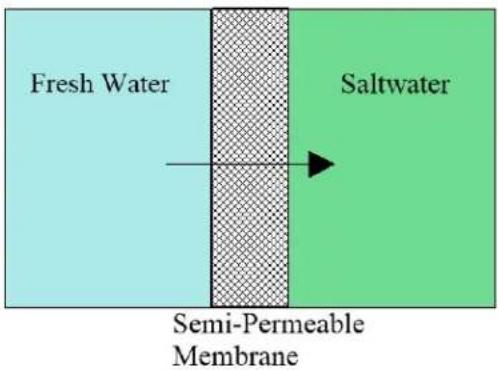
Reverse Osmosis
To reverse this process work is put into the system using a pump. The pump causes pressure to build up on the saltwater side of the membrane. This pressure forces water across the semi-permeable membrane. The membrane is designed to allow the water molecules to pass while preventing the salt and other solids from doing so. Fresh water is collected on the other side of the membrane as a result.
Process of Reverse Osmosis

flowchart
graph LR
    A["Fresh Water"] --> B["Semi-Permeable Membrane"]
    B --> C["Saltwater"]
    C --> D["Pump"]
UNIT SPECIFICATIONS
| SE MODEL | 350 | 600-1 | 600-2 | 800 |
| Configuration | 1 Vessel | 1 Vessel | 2 Vessel | 2 Vessel |
| Feed Water Source | Sea Water | Sea Water | Sea Water | Sea Water |
| Rated production gpd (gpm) | 350(0.24) | 600(0.41) | 600(0.41) | 800(0.55) |
| Rejection and Flow Rates | ||||
| Nominal Salt Rejection % | 99.4% | 99.4% | 99.4% | 99.4% |
| Minimum Feed Flow gpm (lpm) | 2.5 (9.5) | 2.5 (9.5) | 2.5 (9.5) | 2.5 (9.5) |
| Minimum Concentrate Flow gpm (lpm) | 2.26 (8.3) | 2.1 (7.9) | 2.1 (7.9) | 1.94 (7.3) |
| Connections | ||||
| Feed inch | ^3/_4 Hose | ^3/_4 Hose | ^3/_4 Hose | ^3/_4 Hose |
| Product inch | 3/8" QC 9.5mm | 3/8" QC 9.5mm | 3/8" QC 9.5mm | 3/8" QC 9.5mm |
| Concentrate inch | 1/2" QC 12.7mm | 1/2" QC 12.7mm | 1/2" QC 12.7mm | 1/2" QC 12.7mm |
| Membranes | ||||
| Membrane Per Vessel | 1 | 1 | 1 | 1 |
| Membrane Quantity | 1 | 1 | 2 | 2 |
| Membrane Size | 2521 | 2540 | 2521 | 2540 |
| Pumps | ||||
| High Pressure Pump Type | Piston | Piston | Piston | Piston |
| HP motor amps | 14.0/7.0 | 14.0/7.0 | 14.0/7.0 | 14.0/7.0 |
| High Pressure Motor HP (kw) | 1.5 | 1.5 | 1.5 | 1.5 |
| Booster motor amps | 7.2/4.3 | 7.2/4.3 | 7.2/4.3 | 7.2/4.3 |
| Booster Pump RPM @ 60 | 1750 | 1750 | 1750 | 1750 |
| Electrical | ||||
| Voltage | 115/230V 60Hz1Φ | 115/230V 60Hz1Φ | 115/230V 60Hz1Φ | 115/230V 60Hz1Φ |
| Amp Draw | 21.2/11.3 | 21.2/11.3 | 21.2/11.3 | 21.2/11.3 |
| System Dimensions | ||||
| L x W x H inch (cm) | 25.75"x16.99"x14.09"(65.4x43.2x35.8) | 25.75"x16.99"x14.09"(65.4x43.2x35.8) | 44.85"x16.99"x14.09"(113.9x43.2x35.8) | 44.85"x16.99"x14.09"(113.9x43.2x35.8) |
| Weight lb. (kg) | 117.5 (53.3) | 120.5 (54.65) | 125 (56.7) | 131 (59.4) |
OPERATION SPECIFICATIONS
BEFORE STARTING
The reverse osmosis process causes the concentration of impurities. The impurities may precipitate (fall out of solution) when their concentration reaches saturation levels when operated beyond rated production. This precipitation can scale or foul the membranes. In order to prevent this, your SE unit should never be operated over the rated production listed in the UNIT SPECIFICATIONS chart (page 8) and also should not be run above 850psi pump pressure. Water temperature and inlet water ppm are variables that affect flow rate and pump pressure

CAUTION: THE RATED PRODUCTION WILL HAVE TO BE CORRECTED FOR TEMPERATURE OF THE SEA WATER WHEN DETERMINING RATED FLOW FOR YOUR UNIT. SEE 'TEMPERATURE CORRECTION FACTORS FOR WATER PRODUCTION' CHART (PAGE 12-13) FOR AN EXAMPLE ON CORRECTING THE RATED FLOW RATE.
PRE-FILTRATION
SE-Series systems are supplied with a 25-micron (part number 252404292) and 5-micron (part number 252404291) HIGH CAPACITY sediment filters. These filters are made from Typar™ filter media and contain 30% more media than most 2.5" x 10" pleated sediment cartridges. To prevent damage to the system, we recommend using the sediment filters supplied with this system. Change the pre-filters once the pressure gauge labeled FILTER OUT is 15psi or lower.
BOOSTER PUMP
SE-series systems are supplied with a stainless steel centrifugal pump. The pump must be located below the water line to maintain a positive suction head for priming purposes. Refer to page 94 for the booster pump manual.

THE BOOSTER PUMP MUST NEVER BE RUN DRY. OPERATING THE PUMP WITHOUT SUFFICIENT FEED WATER WILL DAMAGE THE PUMP.
OPERATION SPECIFICATIONS
HIGH PRESSURE PUMP
The pump used on the SE-Series systems is a piston type constructed of stainless steel. Follow these guidelines to ensure proper operation of the pump:
- Refer to the WM series General Pump in manufacturer's index for recommended maintenance (page 88).
- The pump must NEVER be run dry. Operating the pump without sufficient feed water will damage the pump.
- ALWAYS use the required filters when operating the unit. The high pressure pump is susceptible to damage from sediment and debris.
- If any damage occurs to your system's pump, a re-build kit is available. Contact your local dealer or distributor and inform them of your system's model and pump size.
- Follow the instructions in the FWF section on page 42.
MEMBRANES
SE-Series reverse osmosis systems come pre-loaded with DOW FILMTEC ^™ sea water membranes unless otherwise specified. For the best longevity of membranes, use the manufacturer's recommended prefilters, operate it within it limits, and ensure the system is performing its regular FWF. Membrane element guidelines can be found in the Dow FILMTEC ^™ on page 110.
DIVERSION VALVE
The diversion valve controls the product water after the membranes. If the controller determines that the salinity of the water is acceptable, (based on the salinity set point) it will energize the diversion valve solenoid, causing the water to flow to the vessels tank. If the electrical portion of the solenoid fails or the controller fails to energize the solenoid, a manual bypass on the diversion valve may be utilized if the product water is found to be acceptable. Refer to picture on page 55 and the Diversion Valve Manual on page 114.
SYSTEM CONTROLLER
The controller is a logic based pc board that can analyze and control the electrical components within the system. Its primary functions are to monitor safety switches (high and low pressure), perform the program sequence of operations to optimize the start, normal operation, and shutdown sequence. Refer to the Watermaker System Controller Manual on page 76.
OPERATION SPECIFICATIONS
PRODUCT WATER
Dometic SeaXchange SE-Series Reverse Osmosis Systems are designed to produce product water at the capacities indicated. For example, the SE 800 produces 800 gallons per day or 0.55 gallons per minute (800gpd ÷ 24hrs/day ÷ 60mins/hr=0.55gpm) of product water at the listed operating test conditions.
Rejection
The amount of total dissolved solids (TDS) rejected by the membrane is expressed as a percentage. For example, a 99.4% rejection rate means that 99.4% of total dissolved solids do not pass through the membrane. To calculate the % rejection, use the following formula:
$$ \% \text {Rejection} = [ (\text {Feed TDS - Product TDS}) / \text {Feed TDS} ] \times 100 $$
Example:
$$ 99.4 \% = [(35,000 - 210) / 35,000] \times 100 $$
Recovery
The amounts of product water recovered for use is expressed as a percentage. To calculate % recovery, use the following formula:
$$ \% \text {Recovery} = (\text {Product Water Flow Rate / Feed Water Flow Rate}) \times 100 $$
Example:
$$ 36 \% = (1.52 / 4.22) \times 100 $$
NOTE: ALL TDS FIGURES MUST BE EXPRESSED IN THE SAME UNITS, TYPICALLY PARTS PER MILLION (PPM) OR MILLIGRAMS PER LITER (MG/L).
OPERATION SPECIFICATIONS
TEMPERATURE CORRECTION FACTORS FOR WATER PRODUCTION
To find your SE-series unit's rated flow at a given temperature, refer to the chart to find the Temperature Correction Factor (TCF). Divide the rated product flow at 77^ by the TCF. The result is the corrected product flow at current water inlet temperature. The water temperature can be found on the main screen. See the example on the next page.
| Temperature °F (°C) | Temperature Correction Factor | Temperature °F (°C) | Temperature Correction Factor | Temperature °F (°C) | Temperature Correction Factor | Temperature °F (°C) | Temperature Correction Factor | Temperature °F (°C) | Temperature Correction Factor |
| 50.0 (10.0) | 1.711 | 57.2 (14.0) | 1.475 | 64.4 (18.0) | 1.276 | 71.6 (22.0) | 1.109 | 78.8 (26.0) | 0.971 |
| 50.2 (10.1) | 1.705 | 57.4 (14.1) | 1.469 | 64.6 (18.1) | 1.272 | 71.8 (22.1) | 1.105 | 79.0 (26.1) | 0.968 |
| 50.4 (10.2) | 1.698 | 57.6 (14.2) | 1.464 | 64.8 (18.2) | 1.267 | 72.0 (22.2) | 1.101 | 79.2 (26.2) | 0.965 |
| 50.5 (10.3) | 1.692 | 57.7 (14.3) | 1.459 | 64.9 (18.3) | 1.262 | 72.1 (22.3) | 1.097 | 79.3 (26.3) | 0.962 |
| 50.7 (10.4) | 1.686 | 57.9 (14.4) | 1.453 | 65.1 (18.4) | 1.258 | 72.3 (22.4) | 1.093 | 79.5 (26.4) | 0.959 |
| 50.9 (10.5) | 1.679 | 58.1 (14.5) | 1.448 | 65.3 (18.5) | 1.254 | 72.5 (22.5) | 1.090 | 79.7 (26.5) | 0.957 |
| 51.1 (10.6) | 1.673 | 58.3 (14.6) | 1.443 | 65.5 (18.6) | 1.249 | 72.7 (22.6) | 1.086 | 79.9 (26.6) | 0.954 |
| 51.3 (10.7) | 1.667 | 58.5 (14.7) | 1.437 | 65.7 (18.7) | 1.245 | 72.9 (22.7) | 1.082 | 80.1 (26.7) | 0.951 |
| 51.4 (10.8) | 1.660 | 58.6 (14.8) | 1.432 | 65.8 (18.8) | 1.240 | 73.0 (22.8) | 1.078 | 80.2 (26.8) | 0.948 |
| 51.6 (10.9) | 1.654 | 58.8 (14.9) | 1.427 | 66.0 (18.9) | 1.236 | 73.2 (22.9) | 1.075 | 80.4 (26.9) | 0.945 |
| 51.8 (11.0) | 1.648 | 59.0 (15.0) | 1.422 | 66.2 (19.0) | 1.232 | 73.4 (23.0) | 1.071 | 80.6 (27.0) | 0.943 |
| 52.0 (11.1) | 1.642 | 59.2 (15.1) | 1.417 | 66.4 (19.1) | 1.227 | 73.6 (23.1) | 1.067 | 80.8 (27.1) | 0.940 |
| 52.2 (11.2) | 1.636 | 59.4 (15.2) | 1.411 | 66.6 (19.2) | 1.223 | 73.8 (23.2) | 1.064 | 81.0 (27.2) | 0.937 |
| 52.3 (11.3) | 1.630 | 59.5 (15.3) | 1.406 | 66.7 (19.3) | 1.219 | 73.9 (23.3) | 1.060 | 81.1 (27.3) | 0.934 |
| 52.5 (11.4) | 1.624 | 59.7 (15.4) | 1.401 | 66.9 (19.4) | 1.214 | 74.1 (23.4) | 1.056 | 81.3 (27.4) | 0.932 |
| 52.7 (11.5) | 1.618 | 59.9 (15.5) | 1.396 | 67.1 (19.5) | 1.210 | 74.3 (23.5) | 1.053 | 81.5 (27.5) | 0.929 |
| 52.9 (11.6) | 1.611 | 60.1 (15.6) | 1.391 | 67.3 (19.6) | 1.206 | 74.5 (23.6) | 1.049 | 81.7 (27.6) | 0.926 |
| 53.1 (11.7) | 1.605 | 60.3 (15.7) | 1.386 | 67.5 (19.7) | 1.201 | 74.7 (23.7) | 1.045 | 81.9 (27.7) | 0.924 |
| 53.2 (11.8) | 1.600 | 60.4 (15.8) | 1.381 | 67.6 (19.8) | 1.197 | 74.8 (23.8) | 1.042 | 82.0 (27.8) | 0.921 |
| 53.4 (11.9) | 1.594 | 60.6 (15.9) | 1.376 | 67.8 (19.9) | 1.193 | 75.0 (23.9) | 1.038 | 82.2 (27.9) | 0.918 |
| 53.6 (12.0) | 1.588 | 60.8 (16.0) | 1.371 | 68.0 (20.0) | 1.189 | 75.2 (24.0) | 1.035 | 82.4 (28.0) | 0.915 |
| 53.8 (12.1) | 1.582 | 61.0 (16.1) | 1.366 | 68.2 (20.1) | 1.185 | 75.4 (24.1) | 1.031 | 82.6 (28.1) | 0.913 |
| 54.0 (12.2) | 1.576 | 61.2 (16.2) | 1.361 | 68.4 (20.2) | 1.180 | 75.6 (24.2) | 1.028 | 82.8 (28.2) | 0.910 |
| 54.1 (12.3) | 1.570 | 61.3 (16.3) | 1.356 | 68.5 (20.3) | 1.176 | 75.7 (24.3) | 1.024 | 82.9 (28.3) | 0.908 |
| 54.3 (12.4) | 1.564 | 61.5 (16.4) | 1.351 | 68.7 (20.4) | 1.172 | 75.9 (24.4) | 1.021 | 83.1 (28.4) | 0.905 |
| 54.5 (12.5) | 1.558 | 61.7 (16.5) | 1.347 | 68.9 (20.5) | 1.168 | 76.1 (24.5) | 1.017 | 83.3 (28.5) | 0.902 |
| 54.7 (12.6) | 1.553 | 61.9 (16.6) | 1.342 | 69.1 (20.6) | 1.164 | 76.3 (24.6) | 1.014 | 83.5 (28.6) | 0.900 |
| 54.9 (12.7) | 1.547 | 62.1 (16.7) | 1.337 | 69.3 (20.7) | 1.160 | 76.5 (24.7) | 1.010 | 83.7 (28.7) | 0.897 |
| 55.0 (12.8) | 1.541 | 62.2 (16.8) | 1.332 | 69.4 (20.8) | 1.156 | 76.6 (24.8) | 1.007 | 83.8 (28.8) | 0.894 |
| 55.2 (12.9) | 1.536 | 62.4 (16.9) | 1.327 | 69.6 (20.9) | 1.152 | 76.8 (24.9) | 1.003 | 84.0 (28.9) | 0.892 |
| 55.4 (13.0) | 1.530 | 62.6 (17.0) | 1.323 | 69.8 (21.0) | 1.148 | 77.0 (25.0) | 1.000 | 84.2 (29.0) | 0.889 |
| 55.6 (13.1) | 1.524 | 62.8 (17.1) | 1.318 | 70.0 (21.1) | 1.144 | 77.2 (25.1) | 0.997 | 84.4 (29.1) | 0.887 |
| 55.8 (13.2) | 1.519 | 63.0 (17.2) | 1.313 | 70.2 (21.2) | 1.140 | 77.4 (25.2) | 0.994 | 84.6 (29.2) | 0.884 |
| 55.9 (13.3) | 1.513 | 63.1 (17.3) | 1.308 | 70.3 (21.3) | 1.136 | 77.5 (25.3) | 0.991 | 84.7 (29.3) | 0.882 |
| 56.1 (13.4) | 1.508 | 63.3 (17.4) | 1.304 | 70.5 (21.4) | 1.132 | 77.7 (25.4) | 0.988 | 84.9 (29.4) | 0.879 |
| 56.3 (13.5) | 1.502 | 63.5 (17.5) | 1.299 | 70.7 (21.5) | 1.128 | 77.9 (25.5) | 0.985 | 85.1 (29.5) | 0.877 |
| 56.5 (13.6) | 1.496 | 63.7 (17.6) | 1.294 | 70.9 (21.6) | 1.124 | 78.1 (25.6) | 0.982 | 85.3 (29.6) | 0.874 |
| 56.7 (13.7) | 1.491 | 63.9 (17.7) | 1.290 | 71.1 (21.7) | 1.120 | 78.3 (25.7) | 0.979 | 85.5 (29.7) | 0.871 |
| 56.8 (13.8) | 1.486 | 64.0 (17.8) | 1.285 | 71.2 (21.8) | 1.116 | 78.4 (25.8) | 0.977 | 85.6 (29.8) | 0.869 |
| 57.0 (13.9) | 1.480 | 64.2 (17.9) | 1.281 | 71.4 (21.9) | 1.112 | 78.6 (25.9) | 0.974 | 85.8 (29.9) | 0.866 |
OPERATION SPECIFICATIONS
TEMPERATURE CORRECTION FACTORS FOR MEMBRANE (FORMULA)
If a system is rated to produce 1.25 gpm of product water @ 77° F. The same system will produce more water at a higher temperature. It will also produce less water at a lower temperature. Use the temperature correction table to obtain the correct flow.
Corrected Flow Rate = (Measured Rated Flow) ÷ (TCF @ Feed Water Temp.)
Example:
1.25 gpm @ 59° F (1.25÷1.42=.88 gpm)
1.25 gpm @ 77° F (1.25÷1=1.25 gpm)
1.25 gpm @ 84° F (1.25÷0.89=1.4 gpm)
NOTE: Fahrenheit/Celsius conversion: F = (°C × 9/5) + 32
PART 2: INSTALLATION AND COMMISSIONING
INSTALLATION KIT
ITEMS INCLUDED WITH EACH SYSTEM
MAIN INSTALLATION ITEMS
☐ 252404258 – stainless steel booster pump and motor assembly
☐ 252404295 - 2.5" x 10" carbon block filter
☐ 252404172 - 2.5"x 10" double pre-filter assembly
☐ 252404326 – 2.5" filter housing wrench
☐ 252404202 – 20' of 34 " white double walled hose. (Not to be used on the suction side of feed pump. Always use wire reinforced hose from the seacock to the suction side of the feed pump.)
☐ 252404004 – 50' of 14 " Spot Zero white nylon tubing (for FWF)
☐ 252404003 – 50' of 12 " Spot Zero white nylon tubing (for overboard)
☐ 252404002 - 50' of 3/8" Spot Zero white nylon tubing (for product)
☐ 252404099 – (2) 3/8" x 1/2" connectors
□ 252404114 - (2) 3/8" tee
☐ 252404109 – (3) 3/8"QC x 3/8"QC 90° elbow
☐ 252404118 – (18) 3/8" red locking clip
☐ 254404094 – (3) 12 " elbow tube
☐ 252404093-(1) 12 " connector male
□ 252404115 - (2) 12 " tee
☐ 252404115 – (10) 12 " red locking clip
☐ (10) – Blue clamp aid safety covers
☐ (8) – Stainless steel 5/16" x 1" lag bolts
☐ (8) – Stainless steel 5/16" flat washers
CONSUMABLE ITEMS
☐ 252404192 – 2.5" x 10" 25 micron pre-filter
☐ 252404191 - 2.5" x 10"5 micron pre-filter
☐ 252404015 – 21oz. bottle CAT pump oil
□ 252404179 – SW30 2540 membrane
□ 252404178 – SW30 2521 membrane
OPTIONAL ITEMS
☐ 252404298 – high capacity prefilter (4.5" X 20")
☐ 252404317 – high capacity prefilter assembly
☐ 252404225 – remote control and 50' cable
□ 252404121 – spare fitting kit
□ 252404040 – hand held TDS meter
□ Membrane and vessel array upgrade
NOTE: Items listed are 1 unit supplied unless noted within parentheses.
DIMENSIONS
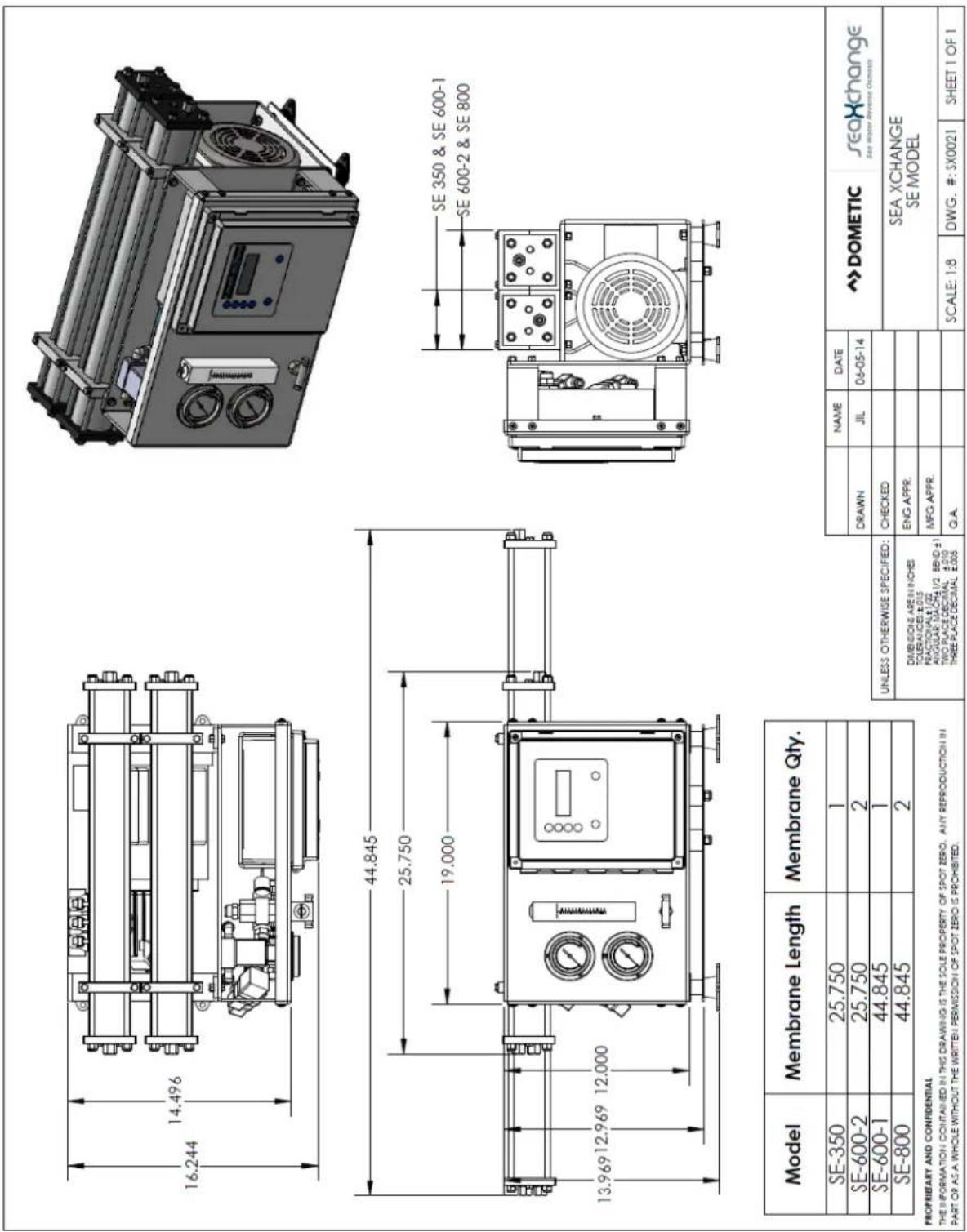
| Model | Membrane Length | Membrane Qty. |
| SE-350 | 25.750 | 1 |
| SE-600-2 | 25.750 | 2 |
| SE-600-1 | 44.845 | 1 |
| SE-800 | 44.845 | 2 |
PROPRIETARY AND CONFIDENTIAL
THE INFORMATION CONTAINED IN THIS DRAWING IS THE SOLE PROPERTY OF SPOT ZERO. ANY REPRODUCTION IN PART OR AS A WHOLE WITHOUT THE WRITTEN PERMISSION OF SPOT ZERO IS PROHIBITED.
DIMENSIONS
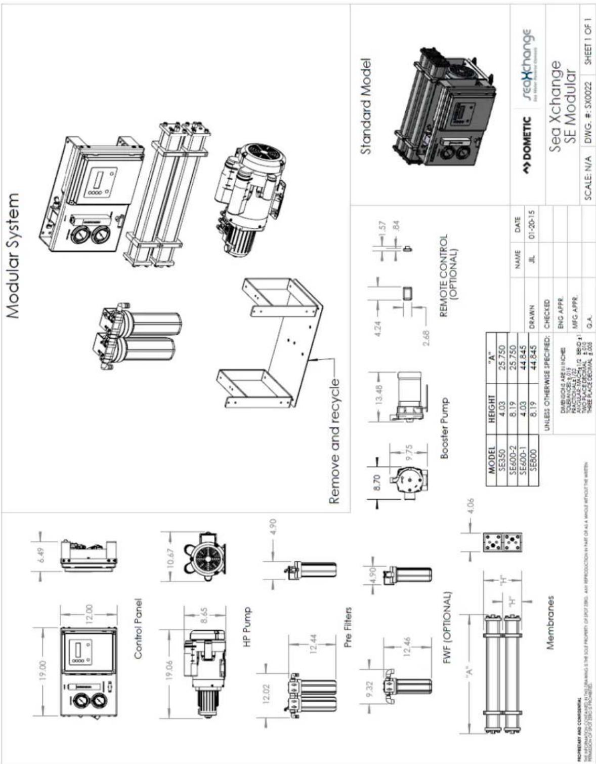
DIMENSIONS
Remote Control (OPTIONAL)

FWF (Optional)

Booster Pump
| MODEL | HEIGHT | "A" |
| SE350 | 4.03 | 25,750 |
| SE600-1 | 8.19 | 25,750 |
| SE600-2 | 4.03 | 44.845 |
| SE800 | 8.19 | 44.845 |

MOUNTING
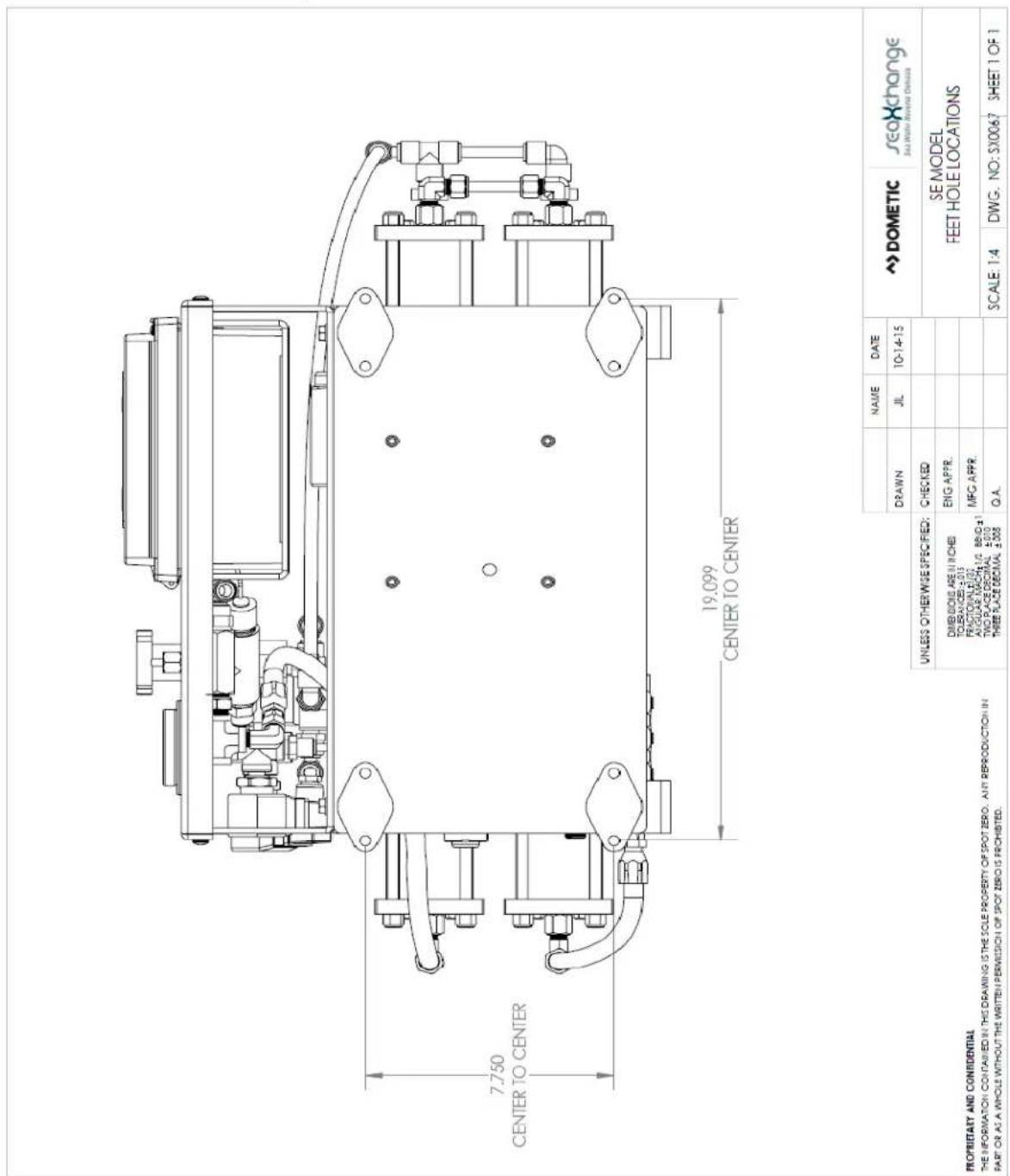
The freestanding system should be bolted down and securely fastened. Refer to mounting template below.
FEET/HOLE LOCATIONS
ELECTRICAL REQUIREMENTS
ELECTRICAL
The SE-Series systems are available in 1 (phase).
• 115 volts at 21.2 amps (including booster pump)
• 230 volts at 11.3 amps (including booster pump)
- 60 Hertz available in both the 115 volt and 230 volt units
NOTE: IT'S RECOMMENDED THAT A QUALIFIED ELECTRICIAN WIRE YOUR SYSTEM IN ACCORDANCE WITH ALL APPLICABLE CODES, RULES, AND REGULATIONS.

WARNING: TO REDUCE THE RISK OF ELECTRICAL SHOCK, THE MING POWER SUPPLY MUST INCLUDE A PROTECTIVE GROUND.
PLUMBING AND PIPING CONNECTIONS
PLUMBING
The membranes and high pressure pumps used on SE-Series Reverse Osmosis Systems require a continuous flow of water with a maximum temperature not to exceed 113°F. Please see Complete Install Guide and the connection drawings on the following pages.

CAUTION: ANY RESTRICTIONS OR BLOCKAGE IN THE CONCENTRATE LINE CAN CAUSE BACKPRESSURE, WHICH WILL INCREASE THE SYSTEM'S OPERATING PRESSURE. THIS CAN RESULT IN DAMAGE TO THE SYSTEM'S MEMBRANES AND COMPONENTS.
PLUMBING AND PIPING CONNECTIONS
CONNECTION DIAGRAM

flowchart
graph TD
    A["SHIP'S FRESH WATER TANK"] --> B["PUMP (SHIP'S SUPPLY)"]
    B --> C["3/8" TUBE"]
    C --> D["OVERBOARD"]
    D --> E["1/2" TUBE"]
    E --> F["3/4" HOSE"]
    F --> G["3/4" HOLE"]
    G --> H["FWF (OPTIONAL)"]
    H --> I["1/4" TUBE"]
    I --> J["3/4" HOSE"]
    J --> K["3/4" HOLE"]
    K --> L["WATER LINE"]
    L --> M["SEA COCK (OWNER SUPPLY)"]
    M --> N["SEA STRAINER (OWNER SUPPLY)"]
    N --> O["CHECK VALVE"]
    O --> P["SEA STRAINER (OWNER SUPPLY)"]
    style A fill:#f9f,stroke:#333
    style B fill:#ccf,stroke:#333
    style C fill:#cfc,stroke:#333
    style D fill:#fcc,stroke:#333
    style E fill:#cff,stroke:#333
    style F fill:#ffc,stroke:#333
    style G fill:#cfc,stroke:#333
    style H fill:#cfc,stroke:#333
    style I fill:#cfc,stroke:#333
    style J fill:#cfc,stroke:#333
    style K fill:#cfc,stroke:#333
    style L fill:#cfc,stroke:#333
    style M fill:#cfc,stroke:#333
    style N fill:#cfc,stroke:#333
    style O fill:#cfc,stroke:#333
    style P fill:#cfc,stroke:#333
PLUMBING AND PIPING CONNECTIONS
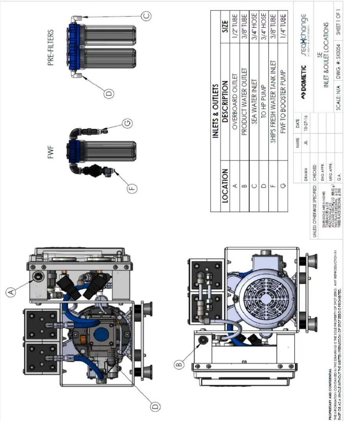
INLETS AND OUTLETS
| INLETS & OUTLETS | ||
| LOCATION | DESCRIPTION | SIZE |
| A | OVERBOARD OUTLET | 1/2" TUBE |
| B | PRODUCT WATER OUTLET | 3/8" TUBE |
| C | SEA WATER INLET | 3/4" HOSE |
| D | TO HP PUMP | 3/4" HOSE |
| F | SHIPS FRESH WATER TANK INLET | 3/8" TUBE |
| G | FWF TO BOOSTER PUMP | 1/4" TUBE |
| NAME | DATE | →DOMETIC | |||
| DRAWN | JIL | 10-27-16 | seaXchange | ||
| UNLESS OTHERWISE SPECIFIED: | CHECKED | SEINLET &OULET LOCATIONS | |||
| DIMENSIONS ARE IN INCHES TOLERANCES ±0.018 PRACTIONALES±1/22 ANGULAR MACHA±1/2 BBID ±1 TWO PLACE DECIMAL ±0.010 THREE PLACE DECIMAL ±0.005 | ENG APPR. | ||||
| MFG APPR. | |||||
| Q.A. | SCALE:N/A | DWG.#: SX0054 SHEET 1 OF 1 | |||
PROPRIETARY AND CONFIDENTIAL
THE INFORMATION CONTAINED IN THIS DRAWING IS THE SOLE PROPERTY OF SPOT ZERO. ANY REPRODUCTION IN PART OR AS A WHOLE WITHOUT THE WRITTEN PERMISSION OF SPOT ZERO IS PROHIBITED.
SYSTEM LAYOUT AND SCHEMATICS
SE SERIES PIPING DIAGRAM

flowchart
graph TD
    A["CHECK VALVE"] --> B["BALL VALVE"]
    B --> C["DIVERSION VALVE"]
    C --> D["NEEDLE VALVE"]
    D --> E["SOLENOID VALVE"]
    F["SHIPS FRESH WATER TANK"] --> G["SHIPS FRESH WATER PUMP"]
    G --> H["FWF (OPTIONAL)"]
    H --> I["BOOSTER PUMP"]
    I --> J["SEA STRAINER"]
    J --> K["SEA COCK"]
    K --> L["SEA WATER INTAKE"]

    M["PRODUCT TO TANK"] --> N["TDS PROBE"]
    N --> O["MEMBRANE PRODUCT"]
    O --> P["MEMBRANES"]
    P --> Q["MEMBRANE RETURN"]
    Q --> R["PUMP PRESSURE"]
    R --> S["NEEDLE VALVE"]
    T["PRODUCT DISCHARGE"] --> U["DISCHARGE OVERBOARD"]

    V["WATER LINE"] --> W["WATER LINE"]

    X["UNLESS OTHERWISE SPECIFIED"] --> Y["DRAWN"]
    Y --> Z["CHECKED"]
    Z --> AA["ENQ APPR."]
    AA --> AB["MFG APPR."]
    AB --> AC["QA"]

    AD["DOMETIC SEA XCHANGE Se/SXII PIPING & INSTRUMENTATION"] --> AE["SCALED N/A DWG, SPX0036 SHEET 1 OF 1"]
SYSTEM LAYOUT AND SCHEMATICS
SE SERIES ELECTRICAL DIAGRAM

COMPLETE INSTALL GUIDE
SEA WATER PLUMBING CONNECTIONS
- Locate a dedicated sea cock to be used for booster pump supply. Sea cock should be a minimum of 3/4" with a speed scoop to prevent a Venturi effect while vessel is underway.
- Install a sea strainer with at least a 50 mesh rating after sea cock.
- Install supplied booster pump below water line.


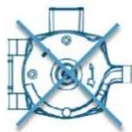
NOTE - BOOSTER PUMP OUTLET MUST REMAIN THE HIGHEST POINT OF PUMP AND CANNOT BE ROTATED 90 OR 180 DEGREES.
- Run reinforced suction hose from sea cock to sea strainer to booster pump in an upward flow manner to prevent air traps.

NOTES:
1) THRU HULL INLET, BALL VALVE, HOSE AND STRAINER SHOULD BE SIZED NO SMALLER THAN PUMP INLET.
2) INSTALL THRU HULL FITTING AS FAR BELOW THE WATER LINE AS POSSIBLE.
3) PUMP NEEDS DEDICATED THRU HULL NOT SHARED WITH OTHER PUMPS.
4) AVOID OR MINIMIZE 90" ELBOW FITTINGS AS MUCH AS POSSIBLE, ROTATE PUMP HEAD TOWARDS DIRECTION OF WATER FLOW.
COMPLETE INSTALL GUIDE
SEA WATER PLUMBING CONNECTIONS
- Use supplied white 3/4" flexible hose from discharge of booster pump to Pre-Filter Inlet connection on Sea Xchange Sediment filter assembly located on left side of system. Filter assembly may be remote mounted if desired. Be sure that there are no kinks in hose run and avoid 90's where possible to prevent restricted flow.
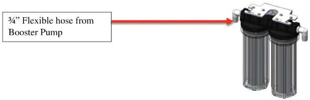
- Double clamp all sea water hose connections to prevent potential leaks.
- Locate connection labeled "Overboard" on lower left side of system. Run supplied white 1/2" tube to a dedicated overboard connection.
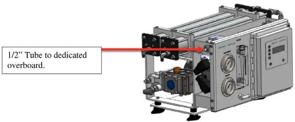
WARNING - SEA WATER OVERBOARD MUST NEVER BE CLOSED OR OBSTRUCTED WHILE SYSTEM IS OPERATIONAL. CLOSING OR OBSTRUCTING THE OVERBOARD FLOW ON SYSTEM MAY CAUSE PERMANENT DAMAGE TO SYSTEM.
COMPLETE INSTALL GUIDE
PRODUCT TO TANK CONNECTION
- Locate the fitting labeled Product to Tank on left side of system. Connect supplied white 3/8" tubing from system to the highest point of the vessels fresh water tank.

WARNING - SHIPS FRESH WATER TANK MUST BE VENTED PROPERLY TO AVOID BACK PRESSURE ON SYSTEM. FAILURE TO DO SO MAY CAUSE PERMANENT DAMAGE TO SYSTEM AND/OR TO NOT FUNCTION PROPERLY.
WARNING - PRODUCT TO TANK MUST NEVER BE CLOSED OR OBSTRUCTED WHILE SYSTEM IS OPERATIONAL. CLOSING OR OBSTRUCTING THE PRODUCT FLOW ON SYSTEM MAY CAUSE PERMANENT DAMAGE TO SYSTEM AND/OR TO NOT FUNCTION PROPERLY.
COMPLETE INSTALL GUIDE
FRESH WATER FLUSH CONNECTION
- Locate filter assembly labeled Fresh Water Flush and connect the inlet of fresh water flush solenoid to the ship's pressurized fresh water system.
NOTE - A SHUT OFF VALVE IS RECOMMENDED TO BE INSTALLED ON SUPPLY LINE TO FRESH FLUSH ASSEMBLY FOR SERVICE.

flowchart
graph TD
    A["Ship's Fresh Water Tank"] --> B["PUMP (SHIP'S SUPPLY)"]
    B --> C["Shipment Volume"]
    C --> D["Output"]
- Run supplied white 14 " tubing from outlet filter assembly labeled Fresh Water Flush and connect to 14 " tubing fitting on face of booster pump.

natural_image
Diagram of a mechanical system with a cylindrical component connected to an electric motor, showing red arrows indicating connection points (no text or symbols present)COMPLETE INSTALL GUIDE
ELECTRICAL CONNECTIONS
- Connect main power supply to main power terminal blocks, connect power to booster pump from contactor as shown below. Ground main power supply and booster pump to grounding bus bar located inside control box.

COMPLETE INSTALL GUIDE
ELECTRICAL CONNECTIONS
- Connect fresh water flush power leads as shown below.
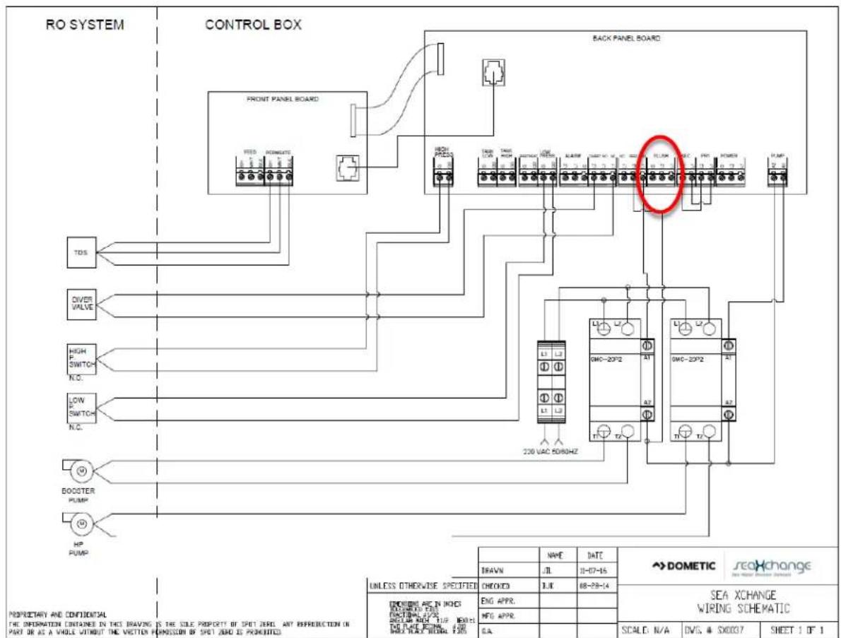
NEW SYSTEM START-UP
INSPECTION
Carefully inspect your system before initial start-up. Check that all plumbing and electrical connections are not loose or have not come undone during shipment. A User's Manual, Test Results, and Filter Housing Wrench will accompany your SE-Series Reverse Osmosis System.
-
Redirect product water to the drain for this procedure.
-
Fully open the concentrate valve by turning it counter clockwise.

- With a flat head screw driver, turn set screw 14 turn clockwise on the Fresh Water Flush solenoid valve (see drawing below). Allow the system to purge 30 minutes to flush the preservative solution from the system.
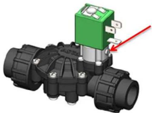
natural_image
3D rendering of a mechanical valve assembly with a green and red component, no visible text or symbolsNEW SYSTEM START-UP
SYSTEM PURGE
- Turn the RO system on and adjust the concentrate valve by turning it clockwise to the specified system's production as noted on page 8, or until system reaches 850 psi: whichever occurs first.

- Inspect the system for leaks.
- After 30 minutes, shut down the system.
- Re-direct the product water back to the tank or point-of-use.
- Record the readings daily for a week; after one week record the readings regularly.
NOTE: USE THE COMMISSIONING REPORT FORM ON THE NEXT PAGE
SEA XCHANGE COMMISSIONING REPORT FORM
System Information:
Model number - ____
Date of Commission - ____
Installed by -
Serial number - ____
Commissioned by-
Vessel hull number-
First step to commissioning a new system is to look over the install to be sure everything is installed correct. This checklist must be gone through prior to powering up the system.
Have all plumbing connections have been made, and secured?
_ Have all plumbing lines been run to the correct locations?
Is the boost pump installed below the water line?
Has wire reinforce hose been used on the suction side of the boost pump?
Is raw water intake open?
Is the overboard open and free of obstructions?
Is the system voltage, hertz, and phase correct?
Is the circuit breaker sized properly with sufficient wire gauge?
Is the power cable connected to the power inlet terminals of the system?
Now power up the system,
Are all displays on and functional?
At this time follow the start-up procedure in the manual and operate the system for an hour at its rated capacity, then record the following data.
System operating readings
Pre-filter inlet ____ psi psi
Concentrate pressure ____ psi
Product flow ____ gpm
Feed water TDS ____ ppm
Hours on system ____ hrs
Location system was tested
Pre-filter outlet ____
Concentrate flow ____ gpm
Product TDS ____ ppm
Feed water temperature ____ F or C
Amp draw ____ Voltage ____
Problems or other notes:
This Page Intentionally Left Blank
The Watermaker System Controller Documentation can be found in the manufacturer's index on page 76. The following is a quick overview of the front panel. Refer to this manual before starting to familiarize yourself with Watermaker Control Switches.

NORMAL OPERATION
START-UP
- Make sure the sea cock to the booster pump is fully open.
- Fully open the concentrate valve by turning counter clockwise (Figure 1).

Figure 1
- Turn the system ON (Figure 2)
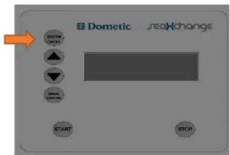
Figure 2
- Press the START button (Figure 3)

Figure 3
- Wait 30 seconds for high pressure pump to turn ON
NORMAL OPERATION
START-UP
- Pressurize the system to the rated flow turning the concentrate valve clockwise or 850 psi, whichever comes first. (Figure 4).

Figure 4
Note:
-
Product water production varies depending on the temperature of the feed water. Refer to temperature correction chart on page 12-13
-
Regulate concentrate valve to reach the rated flow (Figure 5) or 850PSI on the Pump Pressure gauge, whichever comes first.
-
See Table 1 for rated flows by model.
Table 1
| MODEL | GPD | RATED FLOW (GPM) |
| SE350 | 350 | .24 |
| SE600-1 & SE600-2 | 600 | .41 |
| SE800 | 800 | .55 |
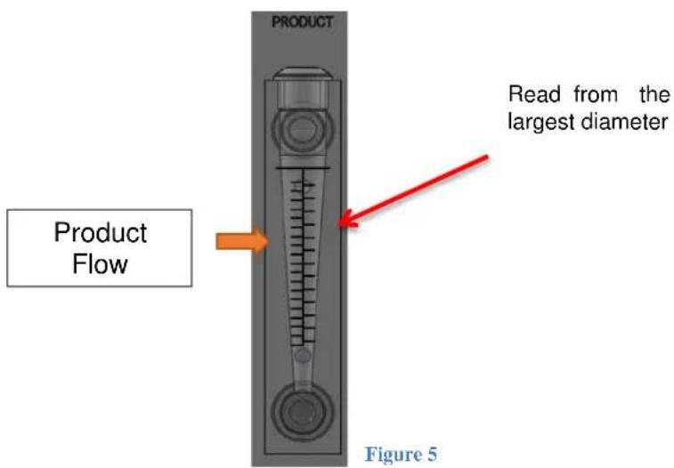
NORMAL OPERATION
SHUTDOWN
- DO NOT leave vessel unattended while the machine is operating!
- Once the vessel's tank is full, press the STOP button (Figure 6).

Figure 5
- Fully open the concentrate valve in order to allow the FWF to clean the membrane and for the next start up (Figure 7).

Figure 6
NOTE: NORMAL OPERATION IS RECOMMENDED WHEN STARTING AND STOPPING THE UNIT. THE REMOTE CONTROL CAN BE USED TO REMOTELY OPERATE THE UNIT IF THE TEMPERATURE AND THE CONCENTRATION (PPM) OF THE SUPPLY WATER DOES NOT CHANGE.
FRESHWATER FLUSH
- The unit will FWF 10 seconds at the beginning of operation.
- The FWF will automatically start after the high pressure pump turns off after each use.
- FWF lasts for 10 minutes after the unit shuts down.
- Leave the system power ON and vessel's fresh water system pressurized for the FWF to flush periodically (occurs automatically and set to happen every 7 days).
NORMAL OPERATION
OPERATIONAL DO'S AND DON'Ts
DO \_
- Change the FWF filter every 4 months.
- Change sediment filters when FILTER OUT gauge reads less than 15psi.
- Monitor the system and keep a daily log.
- Adjust the system concentrate valve to recommended values.
- Always run system with the recommended filters.
DON'T
- Operate above (temperature corrected) rated production.
- Operate above 850psi on pump pressure.
- Permit chlorine to be present in the feed water.
- Shut down the system for extended periods without preservation.
- Close the concentrate valve completely.
- Operate the system with insufficient feed flow.
- Operate the high pressure pump or booster pump dry.
FRESH WATER FLUSH
AUTOMATIC FRESH WATER FLUSH
An automatic fresh water flush occurs when:
• The unit starts (10 second duration).
- The unit is shut down and the high pressure pump shuts off (duration is 10 minutes).
• Every 7 days when the unit power is left ON.
MANUALLY FLUSHING THE SYSTEM (Manual Bypass on solenoid)
The system should be flushed weekly to remove sediment from the surface of the membranes. To manually flush the system, follow the preceding steps:
-
Unit not in operation.
-
Unit electrical supply does not have to be secured.
-
With a flat head screw driver, turn set screw 14 turn clockwise on the FWF solenoid valve (see picture below).

natural_image
3D mechanical component with green and red components, no visible text or symbolsSTORAGE OR WINTERIZATION OF UNIT
Option 1: Storage with Fresh Water Flush
When a system will not be used for a significant period of time (i.e. 3 months – 1 year), the best practice for storage of the system is to allow the automatic fresh water flush to operate by leaving the power to the system on and ensuring that the vessels fresh water system is ON and pressurized. Normal replacement of fresh water flush filter is still required every 4 months.
Option 2: Storage without Fresh Water Flush:
If the vessel will not be able to allow for fresh water flushing over the duration of the storage period, the membrane vessels must have static water replaced with membrane storage chemical solution. Membrane storage chemical part # is 252404263.
Option 3: Winterization
Option 3a: Winterization with membrane rack removal - The best practice for winterization is to remove membrane rack and store with membrane storage chemical in heated storage climate. The remainder of the system should be stored with propylene glycol from sea cock to overboard to prevent freeze damage (propylene glycol can be purchased at most hardware or automotive retailers).
Option 3b: Winterization without membrane rack removal - If the system will be exposed to freezing or near freezing temperature while being stored and the membrane rack can not be removed and stored in heated climate, the following should be done. A 50% solution of storage chemical and 50% propylene glycol, (propylene glycol can be purchased at most hardware or automotive retailers), should be run through the entire system from sea cock to overboard and then close both sea cock and overboard. Membrane storage chemical part # is 252404263.

WARNING: DO NOT USE ETHYLENE GLYCOL, ONLY NON-TOXIC PROPYLENE GLYCOL SHOULD BE USED.
Re-commissioning of System after Storage or Winterization
After storage or winterization, the system must be completely voided of all storage chemical and or propylene glycol. To do this, follow the new system startup guide on page 32.
MEMBRANE REMOVAL AND REPLACEMENT
REMOVAL AND REPLACEMENT
Removing and replacing membranes in the pressure vessels is an easy process if you have the proper information and tools at hand. Please refer to the following instructions when removing and replacing membrane elements.

WARNING: ALL PRESSURE GAUGES MUST READ ZERO BEFORE PROCEEDING. BEFORE ATTEMPTING, DISCONNECT THE POWER FROM THE SYSTEM AND BLEED ALL WATER PRESSURE FROM THE SYSTEM.
NOTE: WEAR GLOVES FOR THE FOLLOWING STEPS IN ORDER NOT TO CONTAMINATE THE MEMBRANE.
- Remove the end plugs from the side of the pressure vessels. This is done by removing the four 3/8" nuts and washers; the end plugs should then freely slide out of the pressure vessel.

-
Remove the replacement membrane element(s) from the shipping box; the membrane(s) should be contained within a plastic oxygen barrier bag.
-
Cut the bag open as close as possible to the seal at one end of the bag, so the bag may be re-used if necessary.
-
Make sure that all parts are clean and free from dirt. Examine the brine seal, and product tube for nicks or cuts. Replace the O-rings or brine seal if damaged.
MEMBRANE REMOVAL AND REPLACEMENT
REMOVAL AND REPLACEMENT
- Flow directions should be observed for installation of each element into its respective pressure vessels.

- Remove one membrane element at a time from the pressure vessels, from the side of each housing. Long nose pliers may be necessary to pull the old membrane element out of the membrane element housing.
- Lubricate the brine seal with a non-petroleum based lubricant, such as Dow Corning® 111 part # 252404879.
- Install membranes with brine seal at the supply side of the vessel
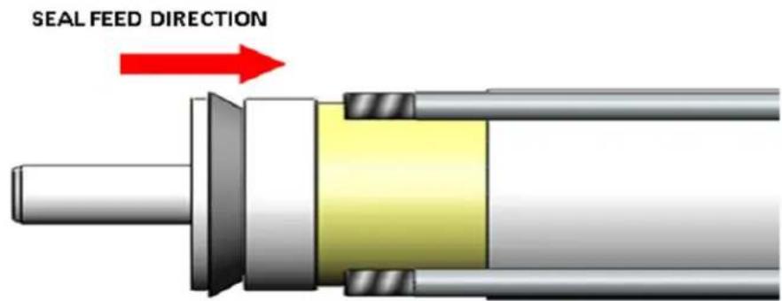
WARNING: THE BRINE SEAL MUST BE IN THE SAME POSITION FOR EACH MEMBRANE ELEMENT HOUSING, SO MARK EACH HOUSING PRIOR TO REMOVING THE MEMBRANE ELEMENTS. THE BRINE SEAL IS A RUBBER SEAL THAT PROTRUDES ON ONE SIDE OF THE MEMBRANE AND IS ALWAYS ON THE FEED SIDE OF THE MEMBRANE ELEMENT.
MEMBRANE REMOVAL AND REPLACEMENT
REMOVAL AND REPLACEMENT
- With a smooth and constant motion, push the membrane element into the housing so the brine seal enters the housing without coming out of the brine seal groove.
- Re-install the end plugs by gently twisting the end cap while pushing it onto the housing. Ensure that you do not pinch or fatigue any O-rings while re-installing the end plug. Push the end plug on until the plug is flush with the pressure vessel.
- Insert the four rods through the plate and fasten using a 3/8 wrench and a flat screw driver.
- Reconnect any fittings that may have been disconnected when the membrane pressure vessels were disassembled.
- To Start-Up the system, please refer to the Normal Start-Up section of this manual. (See page 38)

CAUTION: WET MEMBRANES ARE SHIPPED IN A PRESERVATIVE SOLUTION. THE MEMBRANES MUST BE FLUSHED FOR AT LEAST 30 MINUTES TO REMOVE THE PRESERVATIVE FROM THE MEMBRANE. DISCARD ALL OF THE PRODUCT AND CONCENTRATE, WHICH IS PRODUCED DURING THE FLUSH PERIOD
HIGH PRESSURE PUMP OIL CHANGE
[LC: This section is a terrific improvement and extremely useful. Two questions: When should this oil be changed? What kind of oil should be used?]
OIL CHANGE STEPS
- Run unit for 30 minutes prior to draining oil
- Drain or pump the oil out of the pump. If draining, locate and remove the drain plug, then use a small container that can be placed under the pump casing. (A small hand pump can be used to pump the oil out through the oil fill cap instead of draining the oil through the drain plug.) Dispose of oil properly.
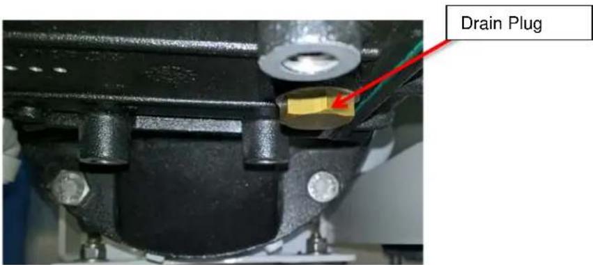
- Install the drain plug back in the high pressure pump.
- Locate and remove oil fill cap.

natural_image
Close-up of a mechanical component with orange cap and red pointer, no visible text or symbolsOil Fill Cap
HIGH PRESSURE PUMP OIL CHANGE
OIL CHANGE STEPS
- Fill oil above the center of sight glass not exceeding the very top of the site glass. (refer to picture below)

natural_image
Close-up of a metallic mechanical component with a circular opening and red internal structure, no visible text or symbols.- Screw fill cap back onto top of high pressure pump
NOTE: OIL LEVEL CAN ONLY BE CHECKED WITH THE UNIT NOT RUNNING
This Page Intentionally Left Blank
PART 4: TROUBLESHOOTING
REVERSE OSMOSIS TROUBLESHOOTING
| SYMPTOMS | POSSIBLE CAUSES | CORRECTIVE ACTION |
| LOW INLET PRESSURE | Low supply pressure Increase Inlet Pressure | |
| Cartridge filters plugged Change Filters | ||
| Leaks Fix any visible leaks | ||
| LOW PRODUCT FLOW | Cold feed water | See temperature correction sheet |
| Low operating pressure | Adjust throttle and concentrate valve | |
| Defective membrane brine seal/Membrane installed backwards | Replace brine seal and / or Reposition membranes | |
| Fouled or Scaled membrane Clean membranes | ||
| Damaged product tube O-rings | Inspect and/or replace | |
| HIGH PRODUCT FLOW | Damaged or oxidized membrane | Replace membrane |
| Exceeding maximum feed water temperature | See temperature correction sheet | |
| Low operating pressure Adjust concentrate valve | ||
| POOR PRODUCT QUALITY | Damage product tube O-rings | Inspect and/or replace |
| Damaged or oxidized membrane | Replace membrane | |
| MEMBRANE FOULING | Scaling (CaSO4, CaSO3, BaSO4, SiO2) | Reduce recovery. Clean with Acid Cleaners |
| Biological Fouling Clean Membranes | ||
| Organic Fouling | Clean with high pH cleaner. | |
| Chlorine Oxidation | Check Chlorine feed equipment and de-chlorination system. | |
NOTE: CONTACT YOUR LOCAL DOMETIC SERVICE DEALER IF FURTHER TROUBLESHOOTING IS NEEDED.
ABNORMAL PRODUCT FLOW
As time progresses, the efficiency of the membrane will be reduced. In general, the salt rejection does not change significantly until two or three years after installation when operated on properly pretreated feed water. The product flow rate will begin to decline slightly after one year of operation, but can be extended with fresh water flushing of the system. A high pH and/or precipitation of hardness can cause premature loss in rejection.
Product flow should be within 20% of the rated production, after correcting the feed water temperatures above or below 77°F. Check your product flow meter and correction chart to determine the product flow rate.
NOTE: TO DETERMINE THE TEMPERATURE CORRECTION FACTOR, LOCATE THE TEMPERATURE CORRECTION TABLE IN THIS USER'S MANUAL ON PAGE 12 AND FOLLOW THE DIRECTIONS.
PRESSURE SWITCH ADJUSTMENT
The low and high pressure switch come factory calibrated. The setting for each switch is the following:
- LP - 5psi
- HP - 950psi
If field calibration is necessary then follow the steps below to adjust the switch.
NOTE: THE SWITCH ADJUSTMENT STEPS ARE THE SAME FOR BOTH LP AND HP SWITCHES
- Locate the switches on the left side of the unit just behind the main panel.

natural_image
Close-up of a mechanical component with black and metallic parts, no visible text or symbolsPRESSURE SWITCH ADJUSTMENT
- Remove the sealed cap from pressure switch

natural_image
Close-up of mechanical components including a black cylindrical device and flanged parts, mounted on a white frame (no visible text or symbols)- Adjust set point with 5/64^th Allen wrench, clockwise to increase setting and counterclockwise to lower the setting.
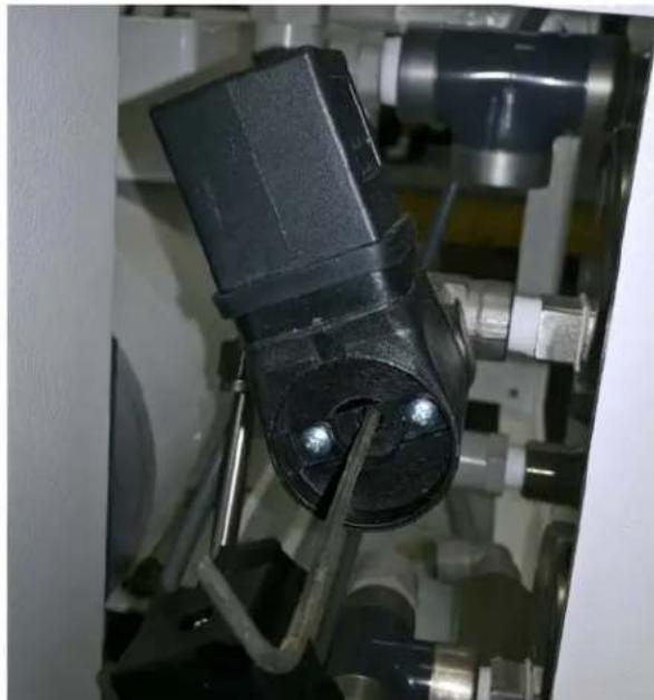
natural_image
Close-up of a mechanical component with black and metallic parts, no visible text or symbolsDIVERSION VALVE
BY-PASS
If the electrical portion of the solenoid fails or the controller fails to energize the solenoid, a manual bypass on the diversion valve may be utilized if the product water is found to be acceptable. Refer to picture below and the Diversion Valve manual on page 114.
NOTE!
- When the manual control is locked, the valve cannot be actuated electrically.
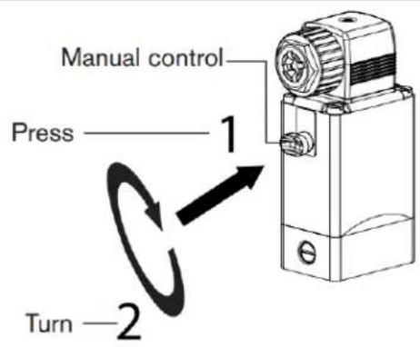
PART 5: PARTS
SE SERIES PARTS LIST
| DRAWING | ITEM | PART NUMBER | DESCRIPTION |
| SE MODEL GENERAL EXPLOSIONPAGE 62 | 1 252404800 | 5/16" x 1" SS HEX FLAT BOLT | |
| 2 252404801 | MOUNT, VIBRATION, 5/16'-18, 1" H X 1-3/8" W | ||
| 3 252404802 | VIBRATION ISOLATOR, 50 LB MAX, 5/16-18 | ||
| 4 252404803 | MOUNT, VIBRATIONA2 , 5/16"-18 THREAD, 160LB CAPACITY | ||
| 5 252404804 | GAUGE, 0-60 PSI, 2.5" DIA, SS, SG, 1/4" MNPT | ||
| 6 252404310 | GAUGE, 0-1500 PSI, 2.5" DIA, SS, SG, 1/4" MNPT | ||
| 7 252404806 | 316 SS Flat Washer 5/16" | ||
| 8 252404807 | 5/16" LOCK WASHER SS | ||
| 9 252404162 | 2.5 GPM STAINLESS STEEL GENERAL PUMP | ||
| 10 252404154 | 1.5 HP MOTOR | ||
| 11 SEE DWG SX0105 | VESSEL ARRAY ASSEMBLY | ||
| 12 252404051 | WATERMAKER CONTROLLER | ||
| SEA EXCHANGE EXPLODED VIEWPAGE 63 | 1 252404179 | SW MEMBRANE 40" LONG | |
| 2 252404312 | SW PRESSURE VESSEL 40" LONG | ||
| 3 252404178 | SW MEMBRANE 20" LONG | ||
| 4 252404281 | SW VESSEL 20" LONG | ||
| CONCENTRATE SIDE PARTSPAGE 64 | 1 252404814 | END PLUG ONE PORT | |
| 2 252404815 | BEARING PLATE ONE PORT | ||
| 3 252404816 | 1/4-20 X BOLT SET OF 4 | ||
| 4 252404817 | HEX PORT | ||
| 5 252404818 | 1/4MNPT X 3/8 COMP. ELBOW SS | ||
| 6 252404868 | 3/8 SS S HP TUBING FOR CONC. SIDE 3" LONG | ||
| 7 252404819 | 3/8-16 LOCK NUT SET OF 8 | ||
| 8 252404820 | END PLUG O-RING | ||
| 9 252404821 | 1/4 SS WASHER |
SE SERIES PARTS LIST
| DRAWING | ITEM | PART NUMBER | DESCRIPTION |
| PRODUCT SIDE PARTSPAGE 65 | 1 2524048 | 22 | END PLUG TWO PORT |
| 2 2524048 | 23 | TWO PORT BEARING PLATE | |
| 3 2524048 | 16 | 1/4-20 X BOLT SET OF 4(B1) | |
| 4 2524048 | 17 | HEX PORT | |
| 5 2524042 | 74 | 1/4MNPT X 3/8 FLARE ELBOW SS | |
| 6 2524041 | 25 | 1/4MNPT X 3/8QC ACETAL | |
| 7 2524048 | 19 | 3/8-16 LOCK NUT SET OF 8 | |
| 8 2524048 | 21 | 3/8 WASHERS SET OF 8 | |
| 9 2524048 | 24 | 3/8QC X 3/8QC ELBOW ACETAL | |
| 10 2524048 | 25 | 3/8QC TEE ACETAL | |
| SW VESSEL O-RINGSPAGE 66 | 1 2524048 | 26 | PORT SEAL O-RING |
| 2 2524048 | 27 | END PLUG SEAL O-RING | |
| 3 2524048 | 28 | HUB SEAL O-RING | |
| SE MOTOR AND PUMP PARTSPAGE 67 | 1 2524041 | 54 | 1.5HP MOTOR |
| 2 2524041 | 62 | GP 2.5 GPM PUMP | |
| 3 2524048 | 08 | 3/8 SSP COUNTERSUNK PLUG | |
| 4 2524048 | 09 | 3/8QC x 1/4QC PLUG IN ELBOW | |
| 5 2524048 | 10 | MALE CONNECTOR 3/8"X1/2" MNPT ACETAL | |
| 6 2524042 | 73 | SSP 3/8 MNPT X 3/8 FLARE STRAIGHT | |
| 7 2524048 | 11 | 3/4" x 1/2" REDUCER NIPPLE NYLON | |
| 8 2524048 | 12 | 3/4" FNPT TO 3/4" BARB ELBOW | |
| 9 2524048 | 13 | 3/8" x 3/4" SS HEX BOLTB1 | |
| 10 2524048 | 05 | GP VENT OIL CAP |
SE SERIES PARTS LIST
| DRAWING | ITEM | PART NUMBER | DESCRIPTION |
| SXII/SE CONTROL PANEL PARTS PAGE 68 | 1 | 252404125 | 1/4MNPT X 3/8QC ACETAL |
| 2 | 252404829 | PLUG IN ELBOW 3/8QC ACETAL | |
| 3 | 252404002 | 3/8 TUBING | |
| 4 | 252404828 | 3/8QC X 3/8QC ELBOW ACETAL | |
| 5 | 252404831 | 1/4 HP SS TEE | |
| 6 | 252404076 | HIGH PRESSURE SWITCH 950PSI | |
| 7 | 252404075 | LOW PRESSURE SWITCH 5PSI | |
| 8 | 252404832 | 3/8MNPT X 3/8QC ACETAL | |
| 9 | 252404833 | 3/8 SS NEEDLE VALVE | |
| 10 | 252404834 | 3/8 X 1/4 REDUCER HEX BUSHINGSS | |
| 11 | 252404274 | 1/4MNPT X 3/8 FLARE HP SS ELBOW | |
| 12 | 252404835 | 1/4" MNPT X 1/4" COMPRESSION ELBOW | |
| 13 | 252404836 | PLUG IN ELBOW 1/4 ACETAL | |
| 14 | 252404837 | 1/4 SCHEDULE 80 SS REINFORCED TEE | |
| SXII/SE CONTROL PANEL PARTS PAGE 69 | 1 | 252404829 | PLUG IN ELBOW 3/8QC ACETAL |
| 2 | 252404832 | 3/8MNPT X 3/8QC ACETAL | |
| 3 | 252404838 | 12 SCHEDULE 80 SS REINFORCED TEE | |
| 4 | 252404839 | TDS PROBE SENSOR-SP5 | |
| 5 | 252404821 | 14 X 14 COMP SS HP ELBOW | |
| 6 | 252404869 | 3/8 HP SEAMLESS TUBING BENT fore P.GAUGE SXII-SE | |
| SXII/SE CONTROL PANEL PARTS PAGE 70 | 1 | 252404002 | 3/8 TUBING |
| 2 | 252404829 | PLUG IN ELBOW 3/8QC ACETAL | |
| 3 | 252404840 | 1/2QC TO 3/8QC REDUCER STRAIGHT | |
| 4 | 252404841 | 1/2QC TEE ACETAL | |
| 5 | 252404003 | 1/2 TUBING | |
| 6 | 252404842 | 1/2QC TO 3/8QC REDUCING ELBOW | |
| 7 | 252404843 | PLUG IN ELBOW 1/2QC ACETAL | |
| 8 | 252404844 | 1/2QC ELBOW ACETAL | |
| 9 | 252404845 | 3/8QC CHECK VALVE ACETAL | |
| 10 | 252404846 | 1/2QC TO 1/2QC BULKHEAD |
SE SERIES PARTS LIST
| DRAWING | ITEM | PART NUMBER | DESCRIPTION |
| SXII/SE CONTROL PANEL PARTS PAGE 71 | 1 2524048 | 47 | 3/8QC TO 3/8QC BULKHEAD |
| 2 2524040 | 02 | 3/8 TUBING | |
| 3 2524041 | 25 | 1/4MNPT X 3/8QC ACETAL | |
| 4 2524040 | 83 | 3/2 BURKERT DIVERSION VALVE-230V | |
| 5 2524042 | 57 | 3/2 BURKERT DIVERSION VALVE-115V | |
| 6 2524048 | 29 | PLUG IN ELBOW 3/8QC ACETAL | |
| 7 2524048 | 48 | DIN CONNECTOR PLUG | |
| SX/XTC/SE PRE-FILTER SUB ASSEMBLY PAGE 72 | 1 2524048 | 54 | 10-24 X 1/2 PAN SS SCREW |
| 2 2524048 | 06 | 5/16 SS WASHER | |
| 3 2524048 | 07 | 5/16 SS LOCK WASHER | |
| 4 2524048 | 00 | 5/16 X 1 SS HEX BOLT | |
| 5 2524048 | 61 | 1/2 MNPT X 3/4 BARB ELBOW NYLON | |
| 6 2524048 | 62 | 1/2 NIPPLE 1.5" THREADED | |
| 7 2524043 | 24 | 2.5 X 10 CLEAR HOUSING | |
| 8 2524048 | 63 | DOUBLE PRE-FILTER BRACKET | |
| 9 2524048 | 36 | 1/4 PLUG IN ELBOW ACETAL | |
| 10 2524048 | 64 | 1/4 MNPT TO 1/4QC CONNECTOR ACETAL | |
| 11 2524042 | 92 | 25 MICRON FILTER | |
| 12 2524042 | 91 | 5 MICRON FILTER | |
| 13 2524048 | 56 | 2.5 x 10 CLEAR HOUSING O-RING | |
| 14 2524048 | 26 | WRENCH FOR 2.5 CELAR HOUSING |
SE SERIES PARTS LIST
| DRAWING | ITEM | PART NUMBER | DESCRIPTION |
| SXII/XTC/SE FRESH WATER FLUSH SUB ASSY PAGE 73 | 1 252404324 | 2.5 X 10 CLEAR HOUSING | |
| 2 252404849 | 3/8 TO 1/4QC STEM REDUCER | ||
| 3 252404850 | 1/2 MNPT X 3/8QC CONNECTOR ACETAL | ||
| 4 252404851 | 1/2 THREADED NIPPLE | ||
| 5 252404852 | 1/2 FNPT REINFORCED ELBOW | ||
| 6 252404853 | SINGLE PRE-FILTER BRACKET | ||
| 7 252404354 | 10-24 X 1/2 PAN SS SCREW | ||
| 8 SEE DWG | 2-WAY SOLENOID | ||
| 9 252404855 | DIN CONNECTOR | ||
| 10 252404856 | 2.5 CLEAR HOUSING O-RING | ||
| 11 252404014 | CARBON BLOCK FILTER | ||
| 12 252404800 | 5/16 X 1 SS HEX BOLT | ||
| 13 252404807 | 5/16 SS LOCK WASHER | ||
| 14 252404806 | 5/16 SS WASHER | ||
| 15 252404217 | 1/2 SPRING CHECK VALVE | ||
| 16 252404326 | WRENCH FOR 2.5 CELAR HOUSING | ||
| 17 202404858 | WATER RESTRICTOR 1.0 |
| ITEM # | PART # | DESCRIPTION |
| 1 | 252404800 | 5/16" x 1" SS HEX FLAT BOLT |
| 2 | 252404801 | MOUNT, VIBRATION, 5/16'-18, 1" H X 1-3/8" W |
| 3 | 252404802 | VIBRATION ISOLATOR, 50 LB MAX, 5/16-18 |
| 4 | 252404803 | MOUNT, VIBRATIONA2 , 5/16"-18 THREAD, 160LB CAPACITY |
| 5 | 252404804 | GAUGE, 0-60 PSI, 2.5" DIA, SS, SG, 1/4" MNPT |
| 6 | 252404310 | GAUGE, 0-1500 PSI, 2.5" DIA, SS, SG, 1/4" MNPT |
| 7 | 252404806 | 316 SS Flat Washer 5/16" |
| 8 | 252404807 | 5/16" LOCK WASHER SS |
| 9 | 252404162 | 2.5 GPM STAINLESS STEEL GENERAL PUMP |
| 10 | 252404154 | 1.5 HP MOTOR |
| 11 | SEE DWG SX0105 | VESSEL ARRAY ASSEMBLY |
| 12 | 252404051 | WATERMAKER CONTROLLER |

| NAME | DATE | →DOMETIC √seaXchange | ||||
| DRAWN | JL | 01-13-17 | ||||
| UNLESS OTHERWISE SPECIFIED: | CHECKED | SE MODELGENERAL EXPLOSION | ||||
| DIMENSIONS ARE IN RICHSTOLERANCES: ±0.05FRACTIONAL(1)/82ANGULAR: MACH 1/2 BBID:1TWO PLACE DECIMAL: ±0.01THREE PLACE DECIMAL: ±0.05 | ENG APPR. | |||||
| MFG APPR. | ||||||
| Q.A. | SCALE: 1:16 | DWG. #:SX0104 | SHEET 1 OF 1 | |||
PROPRIETARY AND CONFIDENTIAL
THE INFORMATION CONTAINED IN THIS DRAWING IS THE SOLE PROPERTY OF SPOT ZERO. ANY REPRODUCTION IN PART OR AS A WHOLE WITHOUT THE WRITTEN PERMISSION OF SPOT ZERO IS PROHIBITED.

| ITEM # | PRODUCT # | DESCRIPTION |
| 1 | 252404179 | SW MEMBRANE 40" LONG |
| 2 | 252404312 | SW PRESSURE VESSEL 40" LONG |
| 1 | 252404178 | SW MEMBRANE 20" LONG |
| 2 | 252404281 | SW VESSEL 20" LONG |
PROPRIETARY AND CONFIDENTIAL
THE INFORMATION CONTAINED IN THIS DRAWING IS THE SOLE PROPERTY OF SPOT ZERO. ANY REPRODUCTION IN PART OR AS A WHOLE WITHOUT THE WRITTEN PERMISSION OF SPOT ZERO IS PROHIBITED.
| NAME | DATE | →DOMETIC | seaXchange | |||
| DRAWN | JIL | 01-16-17 | SAH PRODUCTION SUMMARY | |||
| UNLESS OTHERWISE SPECIFIED; | CHECKED | |||||
| DIMENSIONS ARE IN INCHES TOLERANCES ±.015 FRACTIONALE±1/22 ANGULAR: MACH±1/2 BBND±1 TWO PLACE DECIMAL ±.015 THREE PLACE DECIMAL ±.005 | ENG APPR. | SEA XCHANGE VESSEL EXPLODED VIEW | ||||
| MFG APPR. | ||||||
| Q.A. | SCALE: 1:16 | DWG. #: SX0105 | SHEET 1 OF 3 | |||

| NAME | DATE | →DOMETIC seaHchangeBLC MARD PERIOD ONION | ||||
| DRAWN | JILI | 08-07-17 | ||||
| UNLESS OTHERWISE SPECIFIED: | CHECKED | CONCENTRATE SIDE PARTS | ||||
| DIMENSIONS ARE IN INCHES TOLERANCES ±.018 FRACTIONALE±1/22 ANGULAR: MACH±1/2 SEND ±1 TWO PLACE DECIMAL ±.010 THREE PLACE DECIMAL ±.008 | ENG APPR. | |||||
| MFG APPR. | ||||||
| Q.A. | SCALE: 1:16 | DWG. #SX0105 | SHEET 2 OF 4 | |||
| ITEM # | PRODUCT # | DESCRIPTION |
| 1 | 252404814 | END PLUG ONE PORT |
| 2 | 252404815 | BEARING PLATE ONE PORT |
| 3 | 252404816 | 1/4-20 X BOLT SET OF 4 |
| 4 | 252404817 | HEX PORT |
| 5 | 252404271 | 1/4MNPT X 3/8 COMP. ELBOW SS |
| 6 | 252404868 | 3/8 SS S HP TUBING FOR CONC. SIDE 3" LONG |
| 7 | 252404819 | 3/8-16 LOCK NUT SET OF 8 |
| 8 | 252404820 | END PLUG O-RING |
| 9 | 252404821 | 1/4 SS WASHER |
PROPRIETARY AND CONFIDENTIAL
THE INFORMATION CONTAINED IN THIS DRAWING IS THE SOLE PROPERTY OF SPOT ZERO. ANY REPRODUCTION IN PART OR AS A WHOLE WITHOUT THE WRITTEN PERMISSION OF SPOT ZERO IS PROHIBITED.

| ITEM # | PRODUCT # | DESCRPTION |
| 1 | 252404822 | END PLUG TWO PORT |
| 2 | 252404823 | TWO PORT BEARING PLATE |
| 3 | 252404816 | 1/4-20 X BOLT SET OF 4B1 |
| 4 | 252404817 | HEX PORT |
| 5 | 252404274 | 1/4MNPT X 3/8 FLARE ELBOW SS |
| 6 | 252404125 | 1/4MNPT X 3/8QC ACETAL |
| 7 | 252404819 | 3/8-16 LOCK NUT SET OF 8 |
| 8 | 252404821 | 3/8 WASHERS SET OF 8 |
| 9 | 252404109 | 3/8QC X 3/8QC ELBOW ACETAL |
| 10 | 252404114 | 3/8QC TEE ACETAL |
PROPRIETARY AND CONFIDENTIAL
THE INFORMATION CONTAINED IN THIS DRAWING IS THE SOLE PROPERTY OF SPOT ZERO. ANY REPRODUCTION IN PART OR AS A WHOLE WITHOUT THE WRITTEN PERMISSION OF SPOT ZERO IS PROHIBITED.
| NAME | DATE | →DOMETIC | ||||
| DRAWN | JIL | 08-07-17 | ||||
| UNLESS OTHERWISE SPECIFIED: | CHECKED | PRODUCT SIDE PARTS | ||||
| DIMENSIONS ARE IN INCHES TOLERANCES ± 0.15 FRACTIONAL±1/22 ANGULAR: MACH±1/2 BEND ±1 TWO PLACE DECIMAL ±010 THREE PLACE DECIMAL ±008 | ENG APPR. | |||||
| MFG APPR. | ||||||
| Q.A. | SCALE: N/A | DWG.#: SX0105 | SHEET 3 OF 4 | |||
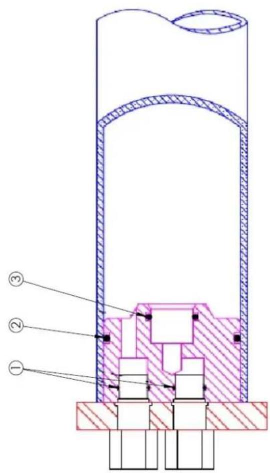
| ITEM # | PART # | DESCRIPTION |
| 1 | 252404826 | PORT SEAL O-RING |
| 2 | 252404820 | END PLUG SEAL O-RING |
| 3 | 252404828 | HUB SEAL O-RING |
SEAL KIT: 252404266
| NAME | DATE | →DOMETIC seaXchangeSau KONOR: DUMA GYNDAY | ||||
| DRAWN | JIL | 08-07-17 | ||||
| UNLESS OTHERWISE SPECIFIED: | CHECKED | SW VESSEL O-RINGS | ||||
| DIMENSIONS ARE IN INCHES TOLERANCES ± 0.10 FRACTIONALE ± 1/2 ANGULAR MACH ± 1/2 BBID ± 1 TWO PLACE DECIMAL ± 0.010 THREE PLACE DECIMAL ± 0.005 | ENG APPR. | |||||
| MFG APPR. | ||||||
| Q.A. | SCALE: N/A | DWG. #SX0105 | SHEET 4 OF 4 | |||
PROPRIETARY AND CONFIDENTIAL
THE INFORMATION CONTAINED IN THIS DRAWING IS THE SOLE PROPERTY OF SPOT ZERO. ANY REPRODUCTION IN PART OR AS A WHOLE WITHOUT THE WRITTEN PERMISSION OF SPOT ZERO IS PROHIBITED.
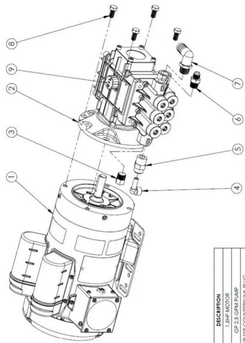
| ITEM # | PART # | DESCRIPTION |
| 1 | 252404154 | 1.5HP MOTOR |
| 2 | 252404162 | GP 2.5 GPM PUMP |
| 3 | 252404808 | 3/8 SSP COUNTERSUNK PLUG |
| 4 | 252404809 | 3/8QC x 1/4QC PLUG IN ELBOW |
| 5 | 252404810 | MALE CONNECTOR 3/8"X1/2" MNPT ACETAL |
| 6 | 252404273 | SSP 3/8 MNPT X 3/8 FLARE STRAIGHT |
| 7 | 252404208 | 1/2" MNPT TO 3/4" BARB ELBOW |
| 9 | 252404813 | 3/8" x 3/4" SS HEX BOLTB1 |
| 10 | 252404805 | GP VENT OIL CAP |
| NAME | DATE | →DOMETIC | ||||
| DRAWN | JIL | 08-03-17 | ||||
| UNLESS OTHERWISE SPECIFIED: | CHECKED | SEMOTOR AND PUMP PARTS | ||||
| DIMENSIONS ARE IN INCHES TOLERANCES ± 0.18 FRACTIONALS±1/22 ANIGULAR MACH±1/2 BEND ±1 TWO PLACE DECIMAL ±0.010 THREE PLACE DECIMAL ±0.005 | ENG APPR. | |||||
| MFG APPR. | ||||||
| Q.A. | SCALE: N/A | DWG. SX0106 | SHEET 1 OF 1 | |||
PROPRIETARY AND CONFIDENTIAL
THE INFORMATION CONTAINED IN THIS DRAWING IS THE SOLE PROPERTY OF SPOT ZERO. ANY REPRODUCTION IN PART OR AS A WHOLE WITHOUT THE WRITTEN PERMISSION OF SPOT ZERO IS PROHIBITED.

| NAME | DATE | →DOMETIC seaXchangeSox Water Rescine Datasets | ||||
| DRAWN | JIL | 08-03-17 | ||||
| UNLESS OTHERWISE SPECIFIED: | CHECKED | |||||
| DIMENSIONS ARE IN INCHES TOLERANCES ±0.05 FRACTIONALS±1/2 ANGULAR MAC#1/2 BEND ±1 TWO PLACE DECIMAL ±0.010 THREE PLACE DECIMAL ±0.006 | ENG APPR. | SXII/SECONTROL PANEL PARTS | ||||
| MFG APPR. | ||||||
| Q.A. | SCALE:N/A | DWG.#: SX0125 | SHEET 1 OF 4 | |||
| ITEM # | PART # | DESCRIPTION |
| 1 | 252404125 | 1/4MNPT X 3/8QC ACETAL |
| 2 | 252404112 | PLUG IN ELBOW 3/8QC ACETAL |
| 3 | 252404002 | 3/8 TUBING |
| 4 | 252404109 | 3/8QC X 3/8QC ELBOW ACETAL |
| 5 | 252404831 | 1/4 HP SS TEE |
| 6 | 252404076 | HIGH PRESSURE SWITCH 950PSI |
| 7 | 252404075 | LOW PRESSURE SWITCH 5PSI |
| 8 | 252404101 | 3/8MNPT X 3/8QC ACETAL |
| 9 | 252404396 | 3/8 SS NEEDLE VALVE |
| 10 | 252404834 | 3/8 X 1/4 REDUCER HEX BUSHINGSS |
| 11 | 252404274 | 1/4MNPT X 3/8 FLARE HP SS ELBOW |
| 12 | 252404270 | 1/4" MNPT X 1/4" COMPRESSION ELBOW |
| 13 | 252404110 | PLUG IN ELBOW 1/4 ACETAL |
| 14 | 252404837 | 1/4 SCHEDULE 80 SS REINFORCED TEE |
PROPRIETARY AND CONFIDENTIAL
THE INFORMATION CONTAINED IN THIS DRAWING IS THE SOLE PROPERTY OF SPOT ZERO. ANY REPRODUCTION IN PART OR AS A WHOLE WITHOUT THE WRITTEN PERMISSION OF SPOT ZERO IS PROHIBITED.

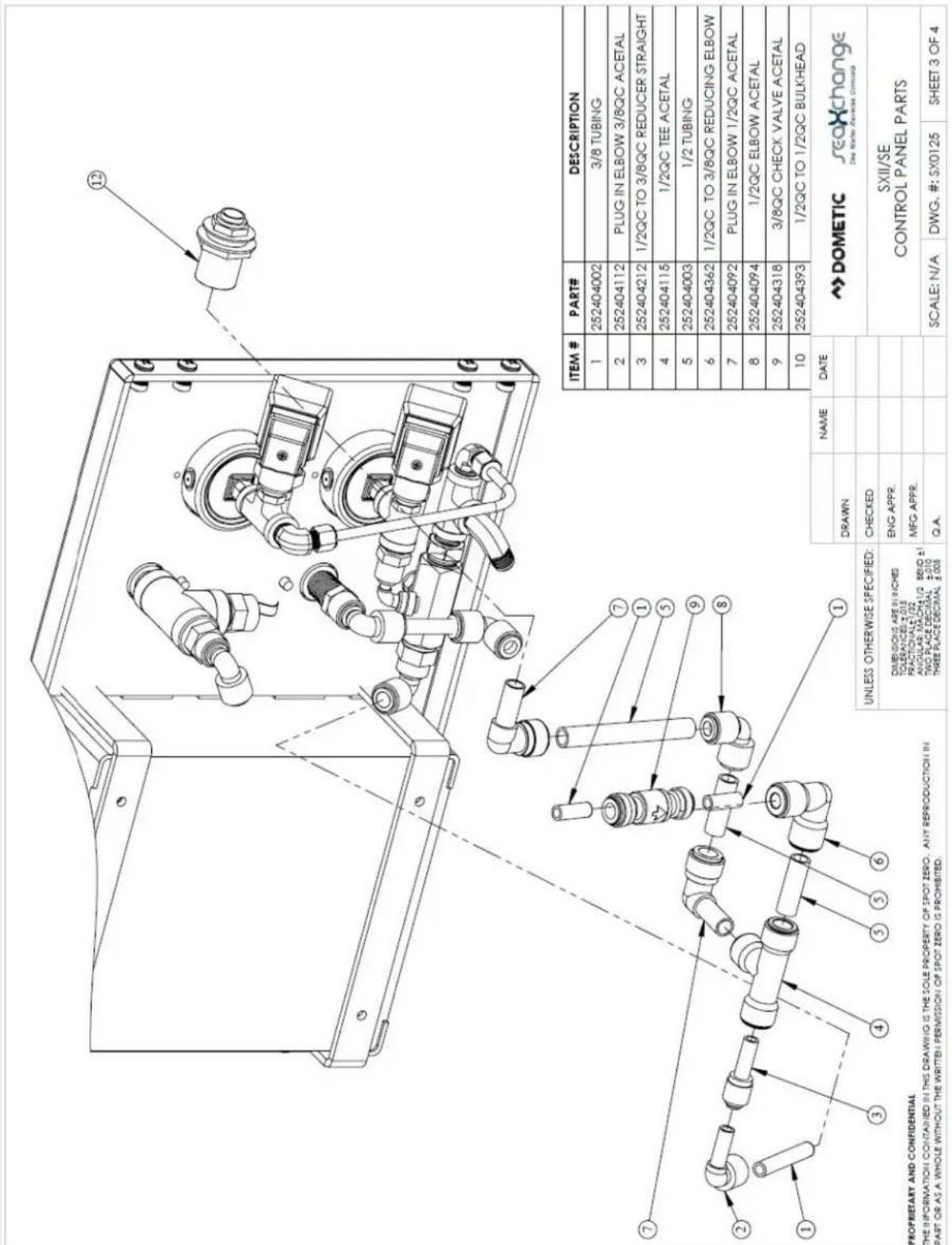

| ITEM # | PART # | DESCRIPTION |
| 1 | 252404392 | 3/8QC TO 3/8QC BULKHEAD |
| 2 | 252404002 | 3/8 TUBING |
| 3 | 252404125 | 1/4MNPT X 3/8QC ACETAL |
| 4 | 252404083 | 3/2 BURKERT DIVERSION VALVE-230V |
| 4 | 252404257 | 3/2 BURKERT DIVERSION VALVE-115V |
| 5 | 252404112 | PLUG IN ELBOW 3/8QC ACETAL |
| 6 | 252404067 | DIN CONNECTOR PLUG |
| NAME | DATE | →DOMETIC | ||||
| DRAWN | JIL | 08-03-17 | ||||
| UNLESS OTHERWISE SPECIFIED: | CHECKED | SXII/SECONTROL PANEL PARTS | ||||
| DIMENSIONS ARE IN INCHES TOLERANCES ±.015 PRACTOIAL±1/22 ANGULAR MACH±1/2 SEND ±1 TWO PLACE DECIMAL ±.010 THREE PLACE DECIMAL ±.005 | ENG APPR. | |||||
| MFG APPR. | ||||||
| Q.A. | SCALE:N/A | DWG.#: SX0125 | SHEET 4 OF 4 | |||
PROPRIETARY AND CONFIDENTIAL
THE INFORMATION CONTAINED IN THIS DRAWING IS THE SOLE PROPERTY OF SPOT ZERO. ANY REPRODUCTION IN PART OR AS A WHOLE WITHOUT THE WRITTEN PERMISSION OF SPOT ZERO IS PROHIBITED.

| ITEM # | PART # | DESCRIPTION |
| 1 | 252404854 | 10-24 X 1/2 PAN SS SCREW |
| 2 | 252404806 | 5/16 SS WASHER |
| 3 | 252404807 | 5/16 SS LOCK WASHER |
| 4 | 252404800 | 5/16 X 1 SS HEX BOLT |
| 5 | 252404208 | 1/2 MNPT X 3/4 BARB ELBOW NYLON |
| 6 | 252404390 | 1/2 NIPPLE 1.5" THREADED |
| 7 | 252404324 | 2.5 X 10 CLEAR HOUSING |
| 8 | 252404863 | DOUBLE PRE-FILTER BRACKET |
| 9 | 252404110 | 1/4 PLUG IN ELBOW ACETAL |
| 10 | 252404100 | 1/4 MNPT TO 1/4QC CONNECTOR ACETAL |
| 11 | 252404018 | 20 MICRON FILTER |
| 12 | 252404019 | 5 MICRON FILTER |
| 13 | 252404127 | 2.5 x 10 CLEAR HOUSING O-RING |
| 14 | 252404326 | WRENCH FOR 2.5 CELAR HOUSING |
FROPRIETARY AND CONFIDENTIAL
THE INFORMATION CONTAINED IN THIS DRAWING IS THE SOLE PROPERTY OF SPOT ZERO. ANY REPRODUCTION IN PART OR AS A WHOLE WITHOUT THE WRITTEN PERMISSION OF SPOT ZERO IS PROHIBITED.
| ITEM # | PART # | DESCRIPTION |
| 1 | 252404324 | 2.5 X 10 CLEAR HOUSING |
| 2 | 252404106 | 3/8 TO 1/4QC STEM REDUCER |
| 3 | 252404099 | 1/2 MNPT X 3/8QC CONNECTOR ACETAL |
| 4 | 252404214 | 1/2 THREADED NIPPLE |
| 5 | 252404852 | 1/2 FNPT REINFORCED ELBOW |
| 6 | 252404039 | SINGLE PRE-FILTER BRACKET |
| 7 | 252404854 | 10-24 X 1/2 PAN SS SCREW |
| 8 | SEE CHART | 2-WAY SOLENOID |
| 9 | 252404278 | DIN CONNECTOR |
| 10 | 252404127 | 2.5 CLEAR HOUSING O-RING |
| 11 | 252404014 | CARBON BLOCK FILTER |
| 12 | 252404800 | 5/16 X 1 SS HEX BOLT |
| 13 | 252404807 | 5/16 SS LOCK WASHER |
| 14 | 252404806 | 5/16 SS WASHER |
| 15 | 252404217 | 1/2 SPRING CHECK VALVE |
| 16 | 252404326 | WRENCH FOR 2.5 CELAR HOUSING |
| 17 | 252404375 | WATER RESTRICTOR 1.0 |
| 2-WAY SOLENOID | ||
| SYSTEM VOLTAGE | SYSTEM MODEL | PART # |
| 115V | SE/SXII | 252404256 |
| 230V | SE/SXII | 252404074 |
| 24V | XTC/XZ | 252404397 |
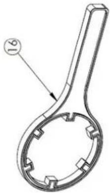
natural_image
Technical line drawing of a mechanical tool handle with circular grooves and a labeled end (no text or symbols present)
PROPRIETARY AND CONFIDENTIAL
THE INFORMATION CONTAINED IN THIS DRAWING IS THE SOLE PROPERTY OF SPOT ZERO. ANY REPRODUCTION IN PART OR AS A WHOLE WITHOUT THE WRITTEN PERMISSION OF SPOT ZERO IS PROHIBITED.
This is a whole without the interest definition of 2.0% risks to sophisticated
PART 6: MANUFACTURERS INDEX
This Page Intentionally Left Blank
Specifications: Table 1 ____ 3
Terminal Board Schematic: Figure 1 ____ 4
Controller Overview: Figure 2 5
Controller Detail, CPU-4 & LP-4: Figure 3____6
Controller Detail, TB-4: Figure 4 7
Conductivity Probe Installation: Figure 5 8
Controller Programming, Internal Menus: Figure 6 ____ 9
Controller Factory Default Settings 10
Controller Fault Conditions 11
Table 1. Specifications
Inputs
| Tank level switches | (2) Normally-Closed. Can be used with a single level switch. |
| Start/Stop | Momentary contact, normally open (RJ45 connector, 8 conductor) |
| Pretreat lockout switch | Normally-Open. |
| High Pressure switch | Normally-Open. |
| Controller Power | 110/240 VAC, 60/50Hz |
| Permeate Conductivity | 0-3000 PPM, 0-6000 μs (standard sensor, CP-1, K=.75) |
| Feed Conductivity | not applicable on Seawater |
Output Relay Ratings (relays are fused with a 6A fuse)
| Feed Valve (Boost Pump Coil) | 1A @ 250VAC (with NO and NC contacts for motorized valves) |
| Flush Valve | 1A @ 250VAC. |
| Divert Valve | 1A @ 250VAC (with NO and NC contacts) |
| Alarm | 1A @ 250VAC |
| HP Pump Motor Coil | 1A @ 250VAC |
Circuit Protection
| Main Power Fuse | F1 | 6 Amp | 5x20mm | LittelFuse O234.006 or Buss GMC-6R |
| Power Supply Fuse | F2 | 1/4 Amp | 5x20mm | LittelFuse O218.250 |
Other
| Dimensions | 10.5" tall, 9.5" wide, 5.0" deep. Nema 4X non-metallic (10x8x4) |
| 12.5" tall, 11.25" wide, 7.0" deep. Nema 4X non-metallic (12x10x6) | |
| 14.5" tall, 13.5" wide, 7.0" deep. Nema 4X non-metallic (14x12x7) | |
| Weight | 4.2 lb. (10.5x9.5) (Enclosure, CPU-4 and TB-4 only.) |
| 6.0 lb. (12.5 x 11.25) (Enclosure, CPU-4 and TB-4 only.) | |
| 10.6 lb. (12.5 x 11.25) (Enclosure, CPU-4 and TB-4 only.) | |
| Environment | 0-50°C, 10-90%RH (non-condensing) |
Rev 4-10-2017
3
Figure 1. Terminal Board Schematic
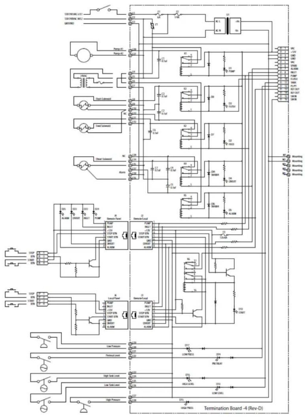
flowchart
graph TD
    subgraph Termination Board -4 (Rev-D)
        A["DC/DC/AC L12"] --> B["Ground"]
        C["DC/DC/AC M12"] --> B
        D["Pump A1"] --> B
        E["Pump A2"] --> B
        F["2V/AC"] --> G["Branch Subword"]
        H["Flash Subword"] --> I["NC"]
        J["Fixed Subword"] --> K["NC"]
        L["Clock/Clock"] --> M["Alarm"]
        N["Alarm"] --> O["Local Panel"]
        P["Stop"] --> Q["Stop"]
        R["Start"] --> S["Start"]
        T["Stop"] --> U["Stop"]
        V["Start"] --> W["Start"]
        X["Stop"] --> Y["Stop"]
        Z["Start"] --> AA["Start"]
        AB["Stop"] --> AC["Stop"]
        AD["Start"] --> AE["Start"]
        AF["Stop"] --> AG["Stop"]
        AH["Start"] --> AI["Stop"]
        AJ["Stop"] --> AK["Stop"]
        AL["Stop"] --> AM["Stop"]
        AN["Stop"] --> AO["Stop"]
        AP["Stop"] --> AQ["Stop"]
        AR["Stop"] --> AS["Stop"]
        AT["Stop"] --> AU["Stop"]
        AV["Stop"] --> AW["Stop"]
        AX["Stop"] --> AY["Stop"]
        AZ["Stop"] --> BA["Stop"]
        BB["Stop"] --> BC["Stop"]
        BD["Stop"] --> BE["Stop"]
        BF["Stop"] --> BG["Stop"]
        BH["Stop"] --> BI["Stop"]
        BJ["Stop"] --> BK["Stop"]
        BL["Stop"] --> BM["Stop"]
        BN["Stop"] --> BO["Stop"]
        BP["Stop"] --> BQ["Stop"]
        BR["Stop"] --> BS["Stop"]
        BT["Stop"] --> BU["Stop"]
        BV["Stop"] --> BW["Stop"]
        BX["Stop"] --> BY["Stop"]
        BZ["Stop"] --> BQ
        CC["Stop"] --> BQ
        DD["Stop"] --> BQ
        DE["Stop"] --> BE
        EF["Stop"] --> BQ
        GF["Stop"] --> BQ
        GH["Stop"] --> BQ
        BIJ["Stop"] --> BQ
        BJX["Stop"] --> BQ
        BKX["Stop"] --> BQ
        BLX["Stop"] --> BQ
        BNX["Stop"] --> BQ
        BOX["Stop"] --> BQ
        BXY["Stop"] --> BQ
        BYX["Stop"] --> BQ
        BZY["Stop"] --> BQ
    end
Rev 4-10-2017
4
Figure 2. Controller Overview

Figure 3. Controller Detail: CPU-4/LP-4
Typical Configuration

Detailed View

Rev 4-10-2017
6
Figure 4. Controller Detail: Terminal Board, TB-4 (See Fig. 1 for schematic)

Switch LEDs
ON when switches close.
Valve LEDs ON when the relay is energized.

Rev 4-10-2017
7
Figure 5. Conductivity Probe Installation

Conductivity Probe Calibration
Because the conductivity measurement is affected by the physical environament in which it operates, it is best to calibrate while installed in the system and operating under normal conditions. This requires an external conductivity measurement device that is known to be accurate to serve as a reference.
- Operate the RO long enough for the membranes, operating temperature and permeate conductivity reading to stabilize.
- Take a sample of the permeate and measure it with the reference meter.
- See Figure 7 for instructions on how to access the Permeate Calibration Menu.
- Enter the Permeate Calibration menu and use the UP or Down arrow until the value on the controller matches the value obtained on the reference meter.
- Exit and Save the calibration.
- The same procedure applies to the Feed Probe calibration.
NOTE: The probe calibration must be performed using solutions with conductivity of less than 900 ppm or s. The conductivity calibration circuit will behave erratically if you attempt to calibrate using a higher value. When using a standard calibration solution, the NaCl PPM value can be used in place of the s value if desired.
Rev 4-10-2017
8
Figure 6. Controller Programming. Accessing the hidden menus.

flowchart
graph TD
    A["System On/Off"] --> B["△"]
    B --> C["▽"]
    C --> D["Manual Run/Flush"]
    E["1. With the System ON, Press and Hold the UP and Down Arrows."] --> F["2. With the UP and Down Arrows depressed, press the Power Switch. The display will switch to the RO Presets menus where a number of settings can be changed."]
    G["START"] --> H["Watermaker Controller"]
    I["STOP"] --> J["STOP"]
Rev 4-10-2017
9
Figure 7. Controller Programming: Menu Navigation

flowchart
graph TD
    A["RO Presets Program 1<br>^v for Other Menus<br>Manual=Edit Sys=Save"] --> B["RO Presets Program 1<br>^v to change setting<br>Manual=Exit Sys=Save"]
    B --> C["VALUES 1,2,3,4"]
    D["Temperature Mode: °C<br>^v for other menus<br>Manual=Edit Sys=Save"] --> E["Temperature Mode: °C<br>^v to change setting<br>Manual=Exit Sys=Save"]
    E --> F["VALUES °C, °F"]
    G["Permeate Probe - uS<br>## uS | ##°C<br>^v for other menus<br>Manual=Edit Sys=Save"] --> H["Permeate Probe: uS<br>## uS | ##°C<br>^v to change setting<br>Manual=Exit Sys=Save"]
    H --> I["VALUES uS, PPM, MΩ, None<br>Note: The MO setting is for use with a resistivity probe for 18MΩ waters<br>Save- Return to RO Display"]
    J["Cal. Permeate Probe<br>## uS | ##°C<br>^v for other menus<br>Manual=Edit Sys=Save"] --> K["Cal. Permeate Probe<br>## uS | ##°C<br>^v to change setting<br>Manual=Exit Sys=Save"]
    K --> L["VALUES 0-990"]
    M["Permeate Alarm Value 50 uS (## ppm)<br>^v for other menus<br>Manual=Edit Sys=Save"] --> N["Permeate Alarm Value 50 uS (## ppm)<br>^v to change setting<br>Manual=Exit Sys=Save"]
    N --> O["VALUES 0-990, Disabled"]
    P["Feed Probe - None<br>^v for other menus<br>Manual=Edit Sys=Save"] --> Q["Feed Probe = None<br>^v to change setting<br>Manual=Exit Sys=Save"]
    Q --> R["VALUES uS, PPM, None"]
    S["LCD Brightness 10<br>^v for other menus<br>Manual=Edit Sys=Save"] --> T["LCD Brightness 10<br>^v to change setting<br>Manual=Exit Sys=Save"]
    T --> U["VALUES 0-15"]
    V["LCD Contrast 15<br>^v for other menus<br>Manual=Edit Sys=Save"] --> W["LCD Contrast 15<br>^v to change setting<br>Manual=Exit Sys=Save"]
    W --> X["VALUES 0-15"]
Rev 4-10-2017
Controller Fault Condition Displays
Below are examples and explanations of the displays which accompany the fault conditions possible in the ROC-3. Fault conditions always indicated a problem of some sort which requires corrective action. The displays provide sufficient information to recognize the source of the fault and the required corrective action.
High Pressure Fault: (Occurs when High Pressure Switch Closes)
Line 1 "Service Fault"
Line 2 "High System Pressure"
Line 3
Line 4 "To Reset Push OFF/ON"
Low Pressure Fault: (System is responding to low pressure condition per system settings)
Line 1 "Service Fault"
Line 2 "Low Feed Pressure"
Line 3
Line 4 "Restart in MM:SS"
Pre Treat Fault: (Pretreat Switch is closed indicating problem with pretreat system).
Line 1 "Service Fault"
Line 2 "Pretreat"
Line 3
Line 4 "Check Pretreat Sys."
Permeate Conductivity Fault: (Permeate conductivity is higher than the alarm setpoint.)
Line 1 "Service Fault"
Line 2 "Permeate TDS xxx ppm" or "Permeate Cond xxx uS"
Line 3 "Alarm SP xxx ppm" or "Alarm SP xxx uS"
Line 4 "To Reset Push OFF/ON"
Feed Conductivity Fault: (Feed conductivity is higher than the alarm setpoint.)
Line 1 "Service Fault"
Line 2 "Feed TDS xxx ppm" or "Feed Cond xxx uS"
Line 3 "Alarm SP xxx ppm" or "Alarm SP xxx uS"
Line 4 "To Reset Push OFF/ON"
Conductivity Probe Error messages:
Line 2 "Over-range" - Measurement is out of range for the circuit, probe may also be shorted
Line 2 "Probe shorted" - Short circuit detected on temperature sensor in probe
Line 2 "Probe not detected" - Open circuit detected on temperature sensor in probe
Line 2 "Probe Startup 1" - Internal reference voltage too high to make valid measurement
Line 2 "Probe Startup 2" - Internal reference voltage too low to make valid measurement
Line 2 "Probe Startup 3" - Internal excitation voltage too high to make valid measurement
Line 2 "Probe Startup 4", - Internal excitation voltage too low to make valid measurement
Rev 4-10-2017
11
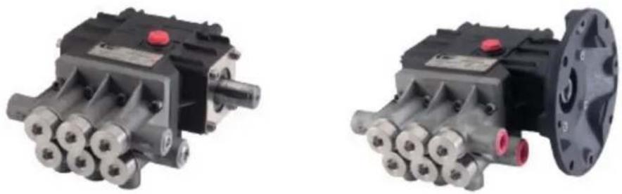
GENERAL HIGH PRESSURE PUMP
GENERAL PUMP A member of the Interpump Group
WM Series
Stainless Steel Triplex Plunger Pump
SERVICING INSTRUCTIONS
SERVICING PUMP PROCEDURES
Valve Replacement: All inlet and discharge valves can be serviced without disrupting the inlet or discharge plumbing.
natural_image
Close-up of a mechanical assembly with a hand using a tool to adjust components (no visible text or symbols)
natural_image
Close-up of a mechanical assembly with a tool and screwdriver, no visible text or symbols
natural_image
Close-up of a mechanical assembly with a hand holding a green tool, no visible text or symbolsTo service any valve:
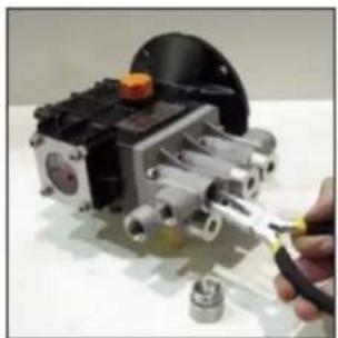
1) Using a 3/8" allen wrench, remove valve cap. Examine threads and o-ring. Replace o-ring if there is any evidence of cuts, abrasions, distortion or wear.
2) Remove valve assembly (retainer, spring, valve, valve seat) from valve cavity.
3) Remove valve seat o-ring from valve cavity.
4) Inspect manifold for wear or damage.
5) Install new o-ring in valve cavity.
6) Insert valve assembly into valve cavity.
7) Coat the threads of the valve cap with Loctite anti-seize 77164 and reinstall valve cap. Torque to 10.8 Nm (8.0 Ft-Lbs).
NOTE: Only one valve kit is necessary to repair all the valves in the pump. The kit includes new o-rings, valve seat, poppet, spring and retainer. All are pre-assembled.
Ref 300789 Rev.C 04-16

General Pump is a member of the Interpump Group


WM Series Servicing Instructions
GENERAL PUMP A member of the Interpump Group

natural_image
Mechanical component with a black housing and orange knob, displayed on a white surface (no visible text or symbols)
natural_image
Close-up of a robotic mechanical device with a hand adjusting its part, no visible text or symbols
natural_image
Close-up of a hand holding a mechanical device with visible components and a small inset component (no text or symbols)Replacing packings using kit WM02:
1) Remove head bolts using 5mm hex wrench and slide manifold away from crankcase. (It is normal for some packing assemblies to remain on the plungers).
Note: it may be necessary to rotate crankshaft and/or use pry bars to separate manifold from crankcase.
2) Inspect plungers for cracks, scoring or build up and replace/dean as needed.

natural_image
Mechanical device with lever and base mount (no visible text or symbols)
natural_image
Close-up of a mechanical component with cylindrical and rectangular features (no visible text or symbols)
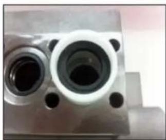
3) Insert 18 mm extractor collet through seal retainer. Tighten collet and extract packing assembly from manifold. Clean and inspect cavity for unusual wear, cracks, etc.
natural_image
Close-up of a metallic mechanical component with two circular cavities and mounting holes (no visible text or symbols)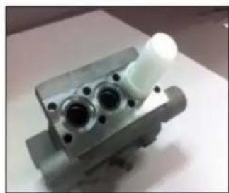
natural_image
Close-up of a metallic mechanical component with multiple cylindrical features and a white cylindrical shaft (no visible text or symbols)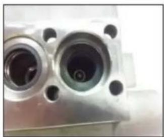
natural_image
Close-up of a metallic mechanical component with two circular openings and mounting holes (no visible text or symbols)4) Note: do not grease any portion of the packing assembly during this process. Set high pressure seal insertion collar in manifold cylinder. Assemble Glyd rings (positions 5 & 6) and gently place inside cylinder tool so they are resting evenly. Insert pusher tool and firmly press down to set packing in manifold.
Ref 300789 Rev.C 04-16
WM Series Servicing Instructions
GENERAL PUMP A member of the Interpump Group

natural_image
Close-up of a finger holding a pair of ring-like objects (no visible text or symbols)
natural_image
Close-up of a hand holding a white plastic object with a dark central hole (no text or symbols visible)
natural_image
Close-up of a mechanical component with a white plastic housing and a metallic ring (no visible text or symbols)5) Set insertion collar over seal casing (position 4) and ensure recess for seal is facing upwards. Gently place low pressure sea (position 2) into collar ensuring the spring side of the seal is facing downward and resting evenly. Insert pusher tool into collar and firmly press down to set seal in casing.
6) Install o-ring (position 3) so it's properly seated in the middle groove on the casing groove that doesn't have through holes. Installation in the wrong groove will impede the flow of cooling water resulting in premature seal failure.

natural_image
Close-up of a metallic mechanical component with two circular holes and a cylindrical shaft (no visible text or symbols)
natural_image
Close-up of a mechanical component with three metallic fittings and a red control knob (no visible text or symbols)
natural_image
Hand holding a mechanical component with no visible text or symbols7) Place seal case into manifold cylinder with low pressure seal facing upwards. Firmly press into cylinder until properly seated and repeat for each cylinder.
8) Rotate crankshaft so center plunger is furthest forward.
9) Slide seal retainer ring over the plunger until seated in crankcase. Ensure o-ring (position 3) is positioned so crankcase opening will receive aligned portion.
Note: a small amount of silicone grease on the back side of the retainer ring will help secure it in place.
10) Slide manifold assembly on to center plunger first, then align to outer plungers while pushing towards crankcase. Note: a pair of make shift 6mm alignment pins will minimize chance of seal damage at this point, see illustration for details.
11) Once manifold is properly seated, install head bolts and begin torque sequence as illustrated. Tighten to 10.8Nm or 8.0 Ft-lbs.

natural_image
Mechanical component with numbered parts, no visible text or symbolsRecommended Tools/Supplies:
100783 Complete Extraction Kit Includes the following tools:
| 2530016 | handle | 2530020 | 15mm sleeve |
| 2530017 | bolt | 2530021 | 18mm sleeve |
| 2530018 | pin |
100295 General Pump Series 100 Oil (1-16 oz. bottle)
100214 General Pump Series 100 Oil (6-16oz. bottles)
100216 General Pump Series 100 Oil (24-16 oz. bottles)
100278 General Pump general packing lubricant
Loctite 77164
Loctite 243
Ref 300789 Rev. C 04-16
PROBLEM
CAUSE
REMEDY
| Pulsation | Valve stuck open. | Check all valves, remove foreign matter. |
| Faulty pulsation damper. | Check precharge; if low, recharge it or install a new one. | |
| Low pressure | Worn nozzle. | Replace nozzle, of proper size. |
| Belt slippage. | Tighten or replace; use correct belt. | |
| Air leak in inlet plumbing. | Disassemble, reseal and reassemble. | |
| Relief valve stuck; partially plugged or improperly adjusted valve seat worn. | Clean, adjust relief valve; check for worn and dirty valve seats. Kit available. | |
| Inlet suction strainer clogged or improperly sized. | Clean. Use adequate size. Check more frequently. | |
| Worn packing. Abrasives in pumped fluid or severe cavitation. Inadequate water. | Install proper filter. Suction at inlet manifold must be limited to lifting less than 20 feet of water or -8.5 PSI vacuum. | |
| Fouled or dirty inlet or discharge valves. | Clean inlet and discharge valve assemblies. | |
| Worn inlet, discharge valve blocked or dirty. | Replace worn valve seats and/or discharge hose | |
| Leaky discharge hose. | ||
| Pump runs extremely rough, pressure very low. | Restricted inlet or air entering the inlet plumbing. | Proper size inlet plumbing; check for air tight seal |
| Inlet restrictions and/or air leaks. Stuck inlet or discharge valve. | Replace worn cup or cups, clean out foreign material, replace worn valves. | |
| Water leakage from under manifold. Slight leakage. | Worn packing. | Install new packing. |
| Cracked plunger. | Replace plunger(s). | |
| Oil leak between crankcase and pumping section. | Worn crankcase piston rod seals. O-rings on plunger retainer worn. | Replace crankcase piston rod seals. Replace o-rings. |
| Oil leaking in the area of crankshaft. | Worn crankshaft seal or improperly installed oil seal o-ring. | Remove oil seal retainer and replace damaged o-ring and/or seals. |
| Bad bearing. | Replace bearing and any spacer or cover damaged by heat. | |
| Excessive play in the end of the crankshaft pulley. | Worn main bearing from excessive tension on drive belt. | Replace crankcase bearing and/ or tension drive belt. |
| Water in crankcase. | May be caused by humid air condensing into water inside the crankcase | Change oil intervals. Use General Pump SAE 30 non-detergent oil. |
| Worn packing and/or piston rod sleeve, o-rings on plunger retainer worn. | Replace packing. Replace o-rings. | |
| Cracked plunger | Replace plunger(s). | |
| Oil leaking from underside of crankcase. | Worn crankcase piston rod seals. | Replace seals. |
| Scored piston rod. | Replace piston rod. | |
| Oil leaking at the rear portion of the crankcase. | Damaged crankcase, rear cover o-ring, drain plug o-ring, or sight glass o-ring. | Replace cover o-ring, drain plug o-ring, or sight glass o-ring. |
| Loud knocking noise in pump. | Pulley loose on crankshaft. | Check key and tighten screw. |
| Broken or worn bearing on rod(s). | Replace bearing or rod(s). | |
| Valve stuck open or shut, or not opening enough. | Replace bad valve. | |
| Frequent or premature failure of the packing. | Scored, damaged or worn plunger. | Replace plungers. |
| Overpressure to inlet manifold. | Reduce inlet pressure. | |
| Abrasive material in the fluid being pumped. | Install proper filtration on pump inlet plumbing. | |
| Excessive pressure and/or temperature of fluid being pumped. | Check pressures and fluid inlet temperature; be sure they are within specified range. | |
| Overpressure of pump. | Reduce pressure. | |
| Running pump dry. | Do not run pump without water. | |
| Upstream chemical injection. | Use downstream chemical injection. |
MAINTENANCE LOG
HOURS & DATE
| OIL CHANGEChange oil after first 50 hours of pump operation, then every 300 hours, or every 3 months, thereafter. (Depending on conditions.) | |||||||
| GREASE | |||||||
| PACKING REPLACEMENT | |||||||
| PLUNGER REPLACEMENT | |||||||
| VALVE REPLACEMENT |

GENERAL PUMP
GP Companies, Inc.
1174 Northland Drive
Mendota Heights, MN 55120
Phone: 651.686.2199 Fax: 800.535.1745
www.generalpump.com email: sales@gpcompanies.com
Ref 300789 Rev.B
03-15
PRICE® BOOSTER PUMP
INSTALLATION, OPERATING AND MAINTENANCE MANUAL
TYPE HP CENTRIFUGAL PUMPS
MODELS:HP75 CN/CS, BN/BS, KN/KS, NN HP75 SS/SC, AB HP100 SS/SC, AB
PLEASE FILL IN FROM PUMP NAMEPLATE
Pump Model
BOM. No.
Serial No.
RETAIN MANUAL FOR REFERENCE
Price® Pump Company
21775 8th. Street East
Sonoma, CA 95476
Tel: 707-938-8441
Fax 707-938-0764
Email: sales@pricepump.com
IN158-HP rev. H
Congratulations
You are now the owner of a Price® Pump Co. Centrifugal Pump. This pump was carefully inspected and subjected to final performance evaluation before being released for shipment. In order to achieve maximum performance and reliability, please follow the simple instructions in this manual.
RECOMMENDED PRECAUTIONS
- For satisfactory operation and safety, maximum system pressure must not exceed 350 psi* (24.6kg/sq cm).
- For satisfactory operation and safety, maximum fluid temperature must not exceed 300^ F* (121°C).
- No modifications, additions or deletions should be made to the pump without prior approval of the factory.
- Drain pump completely and flush with water before servicing a pump handling volatile or harmful liquids.
READ CAREFULLY THE CAUTION BELOW
The performance of your Price® Pump Co. Centrifugal Pump is based on clean, room temperature, water with suction conditions as shown on the performance curves. If used to pump liquids other than water, pump performance may differ from rated performance based on the different specific gravity, temperature, viscosity, etc. of the liquid being pumped. A standard pump, however, may not be safe for pumping all types of liquids, such as toxic, volatile or chemical liquids, or liquids under extreme temperatures or pressures.
Please consult Price® Pump Co. technical specifications as well as local codes and general references to determine the appropriate pump for your particular application. Since it is impossible for us to anticipate every application of a Price® Centrifugal pump, if you plan to use the pump for a non-water application, contact Price® Pump Co. beforehand to determine whether such application may be appropriate and safe under the operating conditions. Failure to do so could result in property damage or personal harm.
* Depends on seal materials and seal type
Visit our website for product information and technical support www.pricepump.com
INSTALLATION / OPERATING INSTRUCTIONS CENTRIFUGAL PUMPS
Warning
Before installing, repairing or performing maintenance on this pump, read these instructions completely.
Disconnect power to pump before servicing to avoid dangerous or fatal electrical shock.
Match supply voltage and frequency to motor nameplate values. Incorrect voltage can cause fire or serious motor damage and void warranty.
Ground motor before connection to electrical power supply! Failure to ground motor can cause severe or fatal electrical shock!
Do not ground to gas supply line!
Before disassembling pump, be certain all liquid has been removed. If pump was used to pump hazardous or toxic fluid, it must be decontaminated prior to disassembly.
Close Coupled Motor Pumps
It is suggested that these pumps be firmly bolted to a level surface. Adequate air movement around motor will help prevent overheating.
Do not over tighten inlet and outlet piping or volute may be damaged.
Power Frame Mounted Pumps
Power Frame mounted pumps must be mounted on a rigid base that will not warp or flex. Each pump must be mounted such that the pump shaft centerline is in-line with the driver shaft centerline. Pads and/or shims will be required on the pump, the driver or both to insure proper alignment. The two shafts should not touch each other (end to end) and the distance between them depends on the coupling used to connect them.
Misalignment will cause vibration, bearing failure and void warranty. Pumps are rough aligned at the factory
but must be realigned after shipment and installation.
Pulley driven pump must have pulleys inline and proper belt tightness practices followed.
Direction of Rotation
Note: Motor shaft rotation is viewed from the suction end of pump. A rotational arrow is shown on the front of the pump volute casing. Incorrect rotation can cause pump damage, failure or reduced performance, voiding warranty. It is best to check rotation by momentarily energizing or jogging the motor prior to filling pump with liquid.
Warning! Do not operate pump without liquid as damage may result to the pump internal wear surfaces.
Plumbing
All piping needs to be supported independently of the pump. Piping connections should not exert any stress on the pump volute or fittings.
Suction Piping (Inlet)
(Horizontal Pumps)
Suction line must provide adequate suction pressure and even (Laminar) liquid flow for proper pump operation. Air, entrapped in the suction line due to leaks or improper piping design, may cause the pump to lose prime. Non-priming pumps must have their suction 'flooded' at start up (see datasheets for minimum NPSHR). Also, the suction line must provide sufficient pressure (NPSH) and even flow to pump inlet to prevent pump cavitation. The suction pipe entering the pump should be straight and a minimum length of 5 times and preferably 10 times the pump inlet diameter. Elbows, fittings or valves installed close to the pump inlet can disrupt liquid flow and cause cavitation. Suction lines must be at least the same diameter as the pump inlet or larger if possible.
Price Pump Company recommends against using foot valves in the suction line to maintain liquid in the pump when it's not operating. If foot valves are used, due to suction lift conditions, they must be properly maintained to avoid
leaks resulting from wear or fouling. Suction piping must be designed to prevent vapor from being trapped in high spots in the piping. This condition may cause the pump to vapor lock.
Discharge Piping (Outlet)
To control flow and discharge head, it is advisable to install a valve (globe, ball, or other adjustable and non-leak type) in the discharge line adjacent to the pump. The valve may be closed during system repairs to prevent backflow. By installing a check valve in the discharge line, backflow can also be prevented during maintenance or during periods of pump stoppage.
Operation
All centrifugal pumps must be filled with liquid prior to start up. It is suggested that during initial start up the discharge valve be closed and then opened as the motor reaches full rpm's. If pump does not build up pressure as motor speed increases, shut down and make sure that liquid flow into pump is not restricted (see "Troubleshooting").
Note: A centrifugal pumps flow rate and head (pressure) will vary with the amount of resistance (pipe friction and flow restrictions) in the discharge line. As the valve on the discharge line opens, the flow rate and motor amperes draw will increase and head (pressure) will decrease. As the valve on the discharge line is closed, the flow rate and amperes draw will decrease and the head (pressure) will increase.
If resistance in the discharge line is not sufficient, the pump will operate at a condition of maximum flow, sometimes called "end of curve" performance.
Maximum horse-power is required to operate at this point and motor overload may result. If excessive amperes draw and motor overload is occurring, reduce the system flow rate by installing a valve or orifice in the discharge line to control (restrict) the pumps flow rate. Alternatively, reduce pump head by trimming impeller to a smaller diameter.
Consult Price Pump or a local Price Pump distributor for assistance.
appsupport@pricepump.com
- Pump fails to build head pressure:
Check for:
a. Pump not primed.
b. Incorrect pump rotation.
c. Driver speed too low.
d. Suction line restricted.
e. Driver failure.
f. Plugged or damaged impeller.
g. Pump or impeller undersized.
h. Pump cavitation.
i. Improper impeller clearance.
- Pump fails to provide enough flow rate.
Check for:
a. System resistance too high.
b. Pump undersized.
c. Pump not primed.
d. Driver speed too low.
e. Poor suction conditions.
f. Im proper impeller clearance.
- Excessive noise or vibration during operation.
Check for:
a. Motor bearing failing.
b. Pump cavitation.
c. Improper impeller clearance.
- Leaking mechanical seal.
Check for:
a. Improper assembly.
b. Worn or cracked seal faces.
c. Abrasive material in fluid.
d. Liquid flashing at seal faces (Fluid temperature too high).
e. Seal pressure rating too low for the service.
f. Chemical attack of seal components.
g. Seal operated dry or with a liquid having poor lubricating properties.
- Pump gradually loses pressure and head.
Check for:
a. Increasing temperature causing cavitation or liquid vaporization.
b. Driver failure.
c. Suction lift too high.
d. Air entering suction line.
- Motor overheating.
Check for:
a. Excessive flow and amp draw (Throttle discharge).
b. Low voltage or frequency.
c. Flow rate too low with resulting heat rise.
d. Bearing failure.
e. System temperature too high.
TYPE HP MAINTENANCE AND REPAIR
Before attempting any repairs under warranty, contact Distributor to obtain factory authorization. Repairs carried out without authorization may void warranty. Many causes of pump system failure are due to improper system design. Refer to the trouble shooting -list in this manual before carrying out pump inspection.
DISASSEMBLY
- Disconnect power source to motor.
- Disconnect electrical connections tagging wires carefully to preserve correct rotation. Loosen motor base.
- Remove pump and motor assembly to repair area. Observe position of all parts prior to disassembly. (Note: Volute may be left in piping.)
- Remove bolts and remove volute from pump.
- Remove impeller. Unscrew CCW. (note: remove center cap from rear of moto r, insert screwdriver to hold shaft while un -screwing impeller).
- Remove seal head from motor shaft. Type 8 & 9: Loosen set screws and slide seal head off shaft.
- Remove motor bolts and remove bracket from motor.
- Remove seal seat from bracket using fingers.
REASSEMBLY
- Clean seat cavity of the bracket thoroughly. (For Bell Gasket Design, assure that there are no cuts or tearing in the end bell gasket.)
- Thoroughly clean pump shaft. Assure that the shaft is not grooved and that there is no evidence of pitting or fretting. Polish the shaft
with extra fine emery cloth if needed. If the shaft is grooved, fretted or worn, replace the motor.
3. For Type 6, 8, 9 and 21 seals:
a. Place the bracket on a firm surface with the seat cavity (pump end) up. (For Bell Gasket Design, place new end bell gasket on bracket).
b. Install seal seat into seat cavity. (For Bell Gasket Design remove the rubber seat cup and discard). Evenly push seat into cavity with fingers. To help ensure the seat is not damaged place cardboard disk over the seat face then gently tap seat into place with a wooden dowel or plastic rod (1 - 1/8" outside diameter).
T6 seal only:
a. Set seal on shaft with carbon facing ceramic seat. Do not push seal head past shoulder on shaft (note: when imp eller is threaded onto motor shaft seal height will automatically be set.)
T21 only:
a. Lubricate shaft and elastomer with vegetable oil.
b. Install rotary seal head onto motor shaft and slide toward seat until carbon face touches seal seat.
c. Install seal spring and seal retainer.
T 8 & 9 only:
a. Install seal head onto pump shaft sliding gently past shoulder of shaft. Slide seal head toward seat until carbon face contacts ceramic seat.
b. Tighten seal head setscrews to pump shaft. Remove clips in seal head and discard.
- Install impeller. Thread impeller onto shaft CW. (For st ainless steel / bronze impellers, apply L octite 242, For CPVC / Noryl impellers, apply L octite 248 or equivalent to the motor shaft before threading the impeller onto the motor shaft) Place screwdriver in motor shaft slot in rear of motor to hold while tightening impeller firmly. (For O-ring Design, install the O- ring on to the bracket face).
Note: For type 21: Ensure that the spring retainer does not slip between the shoulder of the shaft and the hub of the impeller.
- Install volute and tighten bolts evenly (star pattern) to required torque.
Volute Bolt Torque Specifications
SS / Bronze - 10-12 ft/ lbs. (13.5-16.3 Nm)
CPVC - 6 ft / lbs. (9.5 Nm)
Noryl- 10 ft / lbs. (13.5 Nm)
-
Rotate shaft by hand to make sure impeller does not rub against volute.
-
Return pump to installation, reconnect electric connections.
-
Start pump momentarily to observe shaft rotation. If rotation corresponds to the rotation arrow pump may be put into service. If rotation is incorrect, switch any two leads on 3-phase motors. Check the wiring diagram of motor for single phase rotation.
-
Prime pump thoroughly, making sure all air is purged.
-
Start pump allowing adequate time to purge any additional air from system. Observe any gauges, flow meters, etc. to verify that pump is performing properly.
HP75 CN/CS/NN

natural_image
Technical line drawing of an electric motor with visible stator and rotor blades (no text or symbols)HP75 BN/BS/KN/KS/SS/SC/AB

natural_image
Technical line drawing of an electric motor with mounting flanges and housing (no text or symbols)HP100 SS/AB

natural_image
Technical line drawing of a mechanical pump or motor assembly (no text or symbols)INSTALLING A PEO (PUMP END ONLY) STUB SHAFT PUMP
a. Place the bracket on a firm surface, loosen stub shaft setscrews and carefully remove shipping plug.
b. Place motor in an upright position with motor shaft pointing upward. Make sure motor shaft and end bell flange are free of burrs and surfaces are clean.
c. Align PEO stub shaft setscrews (if applicable) with motor shaft keyway and carefully slid the PEO onto the motor shaft until it sits firmly onto the motor end bell flange.
d. Oriented the PEO's discharge port or base to preferred motor configuration while referencing the motors electrical box position.
e. Install flange bolts and tighten. (Install pump base if applicable)
f. Reposition pump back onto motor base.
g. Refer to pump Reassembly Instructions and proceed to setting the impeller clearance (if applicable).
INSTALLING A PEO (PUMP END ONLY) NON-STUB SHAFT PUMP
a. Carefully un-pack all components received with your shipment and remove any shipping plugs.
b. Place the bracket on a firm surface with the s eat cavity (pump end) up. Follow seal Installation / reassembly instructions contained within this manual.
c. Make sure motor shaft and motor end bell flange are free of burrs and surfaces are clean.
d. Carefully place the Bracket assembly over the motor shaft and align bracket with motor end bell flange.
e. Install impeller, gasket or o-ring, volute and volute mounting bolts.
f. Oriented the PEO's discharge port or base to preferred motor configuration while referencing the motors electrical box position.
g. Install motor flange bolts and tighten all bolts to proper torque . (Install pump base if applicable)
PRICE®PUMP CO.
HP75/HP100 (O-Ring Design) Parts List
| Key # | Description | QTY. | HP75/100 SS&SC: | HP75/100 AB: | HP75 NN: |
| A. | Volute HP75 | 1 | 0241(A ^1 ) | 0229-0(A ^1 ) | 8300NN(A ^1 ) |
| Volute HP100 | 1 | 0241-2(A ^2 ) | 0229-2(A ^2 ) | N/A | |
| B. | 1/8" Pipe Plug | 2 | 0559(B ^1 ) | 0558(B ^1 ) | 8012BF(B ^2 )(lea) |
| C. | Volute Bolts | 4 | 0579(C ^1 ) | 0592(C ^1 ) | 0723(C ^2 ) |
| D. | Washers | 12 | N/A | N/A | 1137 |
| E. | Volute Nuts | 4 | N/A | N/A | 1138 |
| F. | Impeller | 1 | 0918SS-(dia.) | 0918BR-(dia.) | N/A |
| Impeller CPVC | 1 | 0918-(dia.) | N/A | 0918-(dia.) | |
| G | Bracket | 1 | 0238(SS)(G ^1 ) | 0242(BR)(G ^1 ) | 8019NN-1(G ^2 ) |
| H ^1 . | T.21 Viton | 1 | 0553 (std) | 0553 (std) | 0553 |
| H ^2 . | T.8 Viton | 1 | 2394-PU | 2394-PU | N/A |
| H ^2 . | T.9 Teflon | 1 | 1150 | 1150 | N/A |
| H ^3 . | T.6 Buna | 1 | N/A | N/A | 0118 (std) |
| J. | O-ring | 1 | 3565 | 3565 | 0871 |
| K. | Slinger | 1 | 0515 | 0515 | 0515 |
| L. | Base | 1 | 0197 | 0197 | 0198 |
| M. | Bolts, Motor | ||||
| Upper | 2 | 0579 | 0579 | 0588 | |
| Lower | 2 | 0724 | 0724 | 0673 | |
| N ^1 . | Motor | 1 | Specify P/N | Specify P/N | Specify P/N |
| N ^2 . | Power Frame | 1 | 5479 | 5479 | 5479 |
HP75 / HP100 Repair Parts Kits (O-ring Design)
(Repair kits for SC pumps only)
| P/N | Includes | P/N | Includes |
| 0661SC-8 | 4.00" CPVC Imp., Viton O-ring, and Slinger | 0661SC-3 | 5.25" CPVC Imp., Viton O-ring, and Slinger |
| 0661SC-6 | 4.25" CPVC Imp., Viton O-ring, and Slinger | 0661SC-2 | 5.50" CPVC Imp., Viton O-ring, and Slinger |
| 0661SC-5 | 4.50" CPVC Imp., Viton O-ring, and Slinger | 0661SC-1 | 5.75" CPVC Imp., Viton O-ring, and Slinger |
| 0661SC-7 | 4.75" CPVC Imp., Viton O-ring, and Slinger | 0661SC | 6.00" CPVC Imp., Viton O-ring, and Slinger |
| 0661SC-4 | 5.00" CPVC Imp., Viton O-ring, and Slinger |
Note: Seal/Seat must be ordered in addition to repair kit
Standard Pump Configurations
| Model: | Volute Material: | Bracket Material: | Impeller Material: |
| SS | 316SS | 316SS | 316SS |
| SC | 316SS | 316SS | CPVC |
| AB | Bronze | Bronze | Bronze |
| NN | Noryl | Noryl | CPVC |

PRICE PUMP CO.
HP75-100_(O-Ring)_P.dwg rev.B
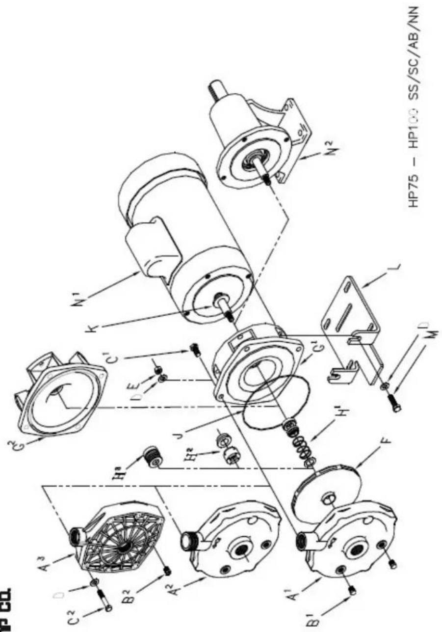
Price* Pump Co. 21775 Eighth Street East * Sonoma, CA 95476-0329 * (707) 938-8441 * Fax (707) 938-0764
PRICE PUMP CO.
HP75 (Gasket Design) Parts List
| Key # | Description | QTY. | HP75 BN/BS: | HP75 KN/KS: | HP75 CN / CS: |
| A. | Volute | 1 | 0229( A^1 ) | 0229KP( A^1 ) | 8300CP( A^2 ) |
| B. | 1/8" Pipe Plug | 2 | 0558( B^1 ) | 0559( B^1 ) | 8012PF( B^2 )(Iea.) |
| C. | Volute Bolts | 4 | 0592( C^1 ) | 0588( C^1 ) | 1136( C^2 ) |
| D. | Washers | 4 | N/A | N/A | 1137 |
| E. | Volute Nuts | 4 | N/A | N/A | 1138 |
| F. | Impeller CPVC | 1 | 0918-(Imp. Dia.) | 0918-(Imp. Dia.) | 0918-(Imp. Dia.) |
| Impeller 316SS | 1 | 0918SS-(Imp. Dia.) | 0918SS-(Imp. Dia.) | 0918SS-(Imp. Dia.) | |
| G^1 . | T.6 Buna (std) | 1 | 0118 | 0118 | 0118 |
| G^2 . | T.21Viton | 1 | 0553 | 0553 | 0553 |
| H. | Gasket, EPDM | 1 | 0232 | 0232 | 0232 |
| J. | Bracket | 1 | 0228 | 0228 | 0228 |
| K. | Slinger | 1 | 0515 | 0515 | 0515 |
| L. | Base | 1 | 0198 | 0198 | 0198 |
| M. | Bolts, Motor Upper | 2 | 0588 | 0588 | 0588 |
| Lower | 2 | 0673 | 0673 | 0673 | |
| N^1 . | Motor | 1 | Specify P/N | Specify P/N | Specify P/N |
| N^2 . | Power Frame | 1 | 5479 | 5479 | 5479 |
HP75 Repair Parts Kits (Bell Gasket Design)
(Repair kits for BN, KN, & CN pumps only)
| P/N | Includes | P/N | Includes |
| 0661-8 | 4.00" CPVC Imp., EPR Gasket, and Slinger | 0661-3 | 5.25" CPVC Imp., EPR Gasket, and Slinger |
| 0661-6 | 4.25" CPVC Imp., EPR Gasket, and Slinger | 0661-2 | 5.50" CPVC Imp., EPR Gasket, and Slinger |
| 0661-5 | 4.50" CPVC Imp., EPR Gasket, and Slinger | 0661-1 | 5.75" CPVC Imp., EPR Gasket, and Slinger |
| 0661-7 | 4.75" CPVC Imp., EPR Gasket, and Slinger | 0661 | 6.00" CPVC Imp., EPR Gasket, and Slinger |
| 0661-4 | 5.00" CPVC Imp., EPR Gasket, and Slinger |
Note: Seal/Seat must be ordered in addition to repair kit.
Standard Pump Configurations
| Model: | Volute Material : | Bracket Material: | Impeller Material: |
| BN | Bronze | Cast Iron | CPVC |
| KN | Kanigen | Cast Iron | CPVC |
| CN | CPVC | Cast Iron | CPVC |
| BS | Bronze | Cast Iron | 316SS |
| KS | Kanigen | Cast Iron | 316SS |
| CS | CPVC | Cast Iron | 316SS |

PRICE PUMP CO.
HP75_(Gasket)_P.dwg rev. B
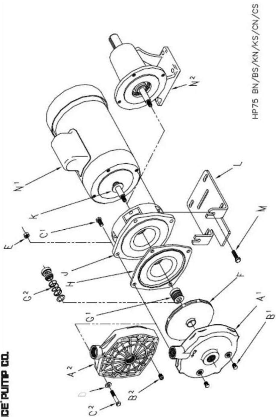
Price® Pump Co. 21775 Eighth Street East * Sonoma, CA 95476-0329 * (707) 938-8441 * Fax (707) 938-0764
PRICE CENTRIFUGAL PUMP CAUTIONS & WARNINGS
• CAUTION: Price Pump centrifugal pumps must be operated above minimum flow rate to avoid damage.
• CAUTION: All Price Pump centrifugal pumps require the suction to be flooded.
• CAUTION: It is recommended that all piping connections to the pump be flexible.
- WARNING: Verify chemical compatibility of the pump materials of construction with the fluid being pumped.
- WARNING: Price centrifugal pumps are not designed for use in sanitary or food applications.
• CAUTION: Use only Price Pump original equipment factory replacement parts.
- WARNING: Price pump fluid temperature limits must be observed. Maximum operating temperature is 300°F.
• CAUTION: The pump should be thoroughly flushed and drained before disassembly.
• CAUTION: For larger pump motor units, weight may exceed 65 lbs. (30 kg).
CAUTION: Maximum working pressure for seals:
| ○ Type 6 Seal | 75 PSI (5.2 bar) |
| ○ Type 6A Seal | 75 PSI (5.2 bar) |
| ○ Type 8 Seal | 325 PSI (22.4 bar) |
| ○ Type 9 Seal | 350 PSI (24.1 bar) |
| ○ Type 21 Seal | 150 PSI (10.3 bar) |
| ○ Type 2106 Seal | 150 PSI (10.3 bar) |
CAUTION: Maximum solid size by pump
| o HP75/MS50 | 0.030" (0.76mm) |
| o SP150 | 0.060" (1.50mm) |
| o LT25 | 0.120" (3.05mm) |
| o F50/75/95 | 0.150" (3.81mm) |
| o OH75 | 0.150" (3.81mm) |
| o CD100/150 | 0.150" (3.81mm) |
| o CL150 | 0.150" (3.81mm) |
| o RC200/300 | 0.380" (9.60mm) |
| o XJ-JB100 | 0.120" (3.05mm) |
| o XJ-JB150 | 0.250" (6.40mm) |
| o XJ-JB200 | 0.440" (11.2mm) |
| o XL-XT100 | 0.120" (3.05mm) |
| o XL-XT150 | 0.250" (6.40mm) |
| o XL-XT200 | 0.440" (11.2mm) |
CAUTION: Minimum flow rate by pump
| o HP75 / MS50 | 0.5 GPM (1.9 LPM) |
| o SP150 | 10 GPM (38 LPM) |
| o LT25 | 0.5 GPM (1.9 LPM) |
| o F50/75/95 | 5.0 GPM (19 LPM) |
| o OH75 | 7.0 GPM (26 LPM) |
| o CD100 | 12 GPM (45 LPM) |
| o CD150 | 25 GPM (94 LPM) |
| o CL150 | 40 GPM (150 LPM) |
| o RC200 | 10 GPM (38 LPM) |
| o RC300 | 50 GPM (189 LPM) |
| o XJ-JB150 | 20 GPM (75 LPM) |
| o XJ-JB150 | 40 GPM (150 LPM) |
| o XJ-JB200 | 90 GPM (340 LPM) |
| o XL-XT100 | 10 GPM (38 LPM) |
| o XL-XT150 | 35 GPM (132 LPM) |
| o XL-XT200 | 50 GPM (189 LPM) |
This Page Intentionally Left Blank
DOW FILMTEC™ MEMBRANES
DOW FILMTEC™ Membranes
DOW FILMTEC Seawater RO Elements for Marine Systems
Features
Improved DOW FILMTEC™ seawater reverse osmosis elements offer the highest productivity while maintaining excellent salt rejection.
- DOW FILMTEC SW30 membrane elements have the highest flow rates available to meet the water demands of both sea-based and land-based desalinators.
- DOW FILMTEC SW30 elements may also be operated at lower pressure to reduce pump size, cost and operating expenses.
- Improved DOW FILMTEC seawater membrane combined with automated, precision element fabrication result in the most consistent product performance available.
Product Specifications
| Product | Part Number | Applied Pressure psig (bar) | Permeate Flow Rate gpd (m3/d) | Stabilized Salt Rejection (%) |
| SW30-2514 | 80733 | 800 (55) | 150 (0.6) | 99.4 |
| SW30-2521 | 80734 | 800 (55) | 300 (1.1) | 99.4 |
| SW30-2540 | 80737 | 800 (55) | 700 (2.6) | 99.4 |
| SW30-4021 | 80740 | 800 (55) | 800 (3.0) | 99.4 |
| SW30-4040 | 80741 | 800 (55) | 1,950 (7.4) | 99.4 |
-
Permeate flow and salt rejection based on the following test conditions: 32,000 ppm NaCl, pressure specified above, 77°F (25°C) and the following recovery rates, SW30-2514 - 2%, SW30-2521 & SW30-4021 - 5%, SW30-2540 & SW30-4040 - 8%.
-
Permeate flows for individual elements may vary +/-20%.
-
For the purpose of improvement, specifications may be updated periodically.
Figure 1


Aimfe selis cualkraar
number 501654 in case in multiple
cualkraarings, baf capier
induces no 2-2-0 EPI cramps.
Aimfe per number 30219
| Product | Maximum Feed Flow Rate gpm (m3/h) | Dimensions – Inches (mm) | |||
| A | B | C | D | ||
| SW30-2514 | 6 (1.4) | 14.0 (356) | 1.19 (30.2) | 0.75 (19) | 2.4 (61) |
| SW30-2521 | 6 (1.4) | 21.0 (533) | 1.19 (30.2) | 0.75 (19) | 2.4 (61) |
| SW30-2540 | 6 (1.4) | 40.0 (1,016) | 1.19 (30.2) | 0.75 (19) | 2.4 (61) |
| SW30-4021 | 16 (3.6) | 21.0 (533) | 1.05 (26.7) | 0.75 (19) | 3.9 (99) |
| SW30-4040 | 16 (3.6) | 40.0 (1,016) | 1.05 (26.7) | 0.75 (19) | 3.9 (99) |
-
Refer to DOW FILMTEC Design Guidelines for multiple-element systems.
-
SW30-2514, SW30-2521 and SW30-2540 elements fit nominal 2.5-inch I.D. pressure vessels. SW30-4021 and SW30-4040 elements fit nominal 4-inch I.D. pressure vessel.
-
Refer to DOW FILMTEC Design Guidelines for multiple-element systems.
Operating Limits
| Membrane Type | Polyamide Thin-Film Composite |
| Maximum Operating Temperature | 113°F (45°C) |
| Maximum Operating Pressure | 1,000 psi (69 bar) |
| Maximum Pressure Drop | 15 psig (1.0 bar) |
| pH Range, Continuous Operationa | 2 - 11 |
| pH Range, Short-Term Cleaningb | 1 - 13 |
| Maximum Feed Silt Density Index | SDI 5 |
| Free Chlorine Tolerancec | <0.1 ppm |
| Maximum temperature for continuous operation above pH 10 is 95°F (35°C).Refer to Cleaning Guidelines in specification sheet 609-23010.Under certain conditions, the presence of free chlorine and other oxidizing agents will cause premature membrane failure.Since oxidation damage is not covered under warranty, DOW FILMTEC recommends removing residual free chlorine by pretreatment prior to membrane exposure. Please refer to technical bulletin 609-22010 for more information. | |
Important Information
Proper start-up of reverse osmosis water treatment systems is essential to prepare the membranes for operating service and to prevent membrane damage due to overfeeding or hydraulic shock. Following the proper start-up sequence also helps ensure that system operating parameters conform to design specifications so that system water quality and productivity goals can be achieved.
Before initiating system start-up procedures, membrane pretreatment, loading of the membrane elements, instrument calibration and other system checks should be completed.
Please refer to the application information literature entitled "Start-Up Sequence" (Form No. 609-02077) for more information.
Operation Guidelines
Avoid any abrupt pressure or cross-flow variations on the spiral elements during start-up, shutdown, cleaning or other sequences to prevent possible membrane damage. During start-up, a gradual change from a standstill to operating state is recommended as follows:
- Feed pressure should be increased gradually over a 30-60 second time frame.
• Cross-flow velocity at set operating point should be achieved gradually over 15-20 seconds.
• Permeate obtained from first hour of operation should be discarded.
General Information
- Keep elements moist at all times after initial wetting.
- If operating limits and guidelines given in this bulletin are not strictly followed, the limited warranty will be null and void.
- To prevent biological growth during prolonged system shutdowns, it is recommended that membrane elements be immersed in a preservative solution.
- The customer is fully responsible for the effects of incompatible chemicals and lubricants on elements.
• Maximum pressure drop across an entire pressure vessel (housing) is 50 psi (3.4 bar). - Avoid static permeate-side backpressure at all times.
DOW FILMTEC™ Membranes
Notice: The use of this product in and of itself does not necessarily guarantee the removal of cysts and pathogens from water. Effective cyst and pathogen reduction is dependent on the complete system design and on the operation and maintenance of the system.
For more information about DOW FILMTEC membranes, call the Dow Water & Process Solutions business:
| North America: | 1-800-447-4369 |
| Latin America: | (-55) 11-5188-9222 |
| Europe: | (-32) 3-450-2240 |
| Pacific: | +60 3 7958 3392 |
| Japan: | +813 5460 2100 |
| China: | +86 21 2301 1000 |
| www.dowwaterandprocess.com | |
Notice: No freedom from any patent owned by Dow or others is to be inferred. Because use conditions and applicable laws may differ from one location to another and may change with time, Customer is responsible for determining whether products and the information in this document are appropriate for Customer's use and for ensuring that Customer's workplace and disposal practices are in compliance with applicable laws and other government enactments. Dow assumes no obligation or liability for the information in this document. NO WARRANTIES ARE GIVEN; ALL IMPLIED WARRANTIES OF MERCHANTABILITY OR FITNESS FOR A PARTICULAR PURPOSE ARE EXPRESSLY EXCLUDED.

This Page Intentionally Left Blank
BURKERT DIVERSION VALVE
Type 0121, 0330, 0331 (0124, 0125, 0332, 0333)
natural_image
Four black industrial hydraulic or pneumatic valve components with no visible text or symbolsInternational address
www.burkert.com
Manuals and data sheets on the Internet: www.burkert.com
1 The operating instructions....2
2 Authorized use....3
3 Basic safety instructions....4
4 System description 5
5 Technical data....6
6 Assembly 8
7 Electrical connection....10
8 Disassembly 12
9 Maintenance, troubleshooting....12
10 Transportation, storage, disposal 13
1 THE OPERATING INSTRUCTIONS
The operating instructions contain important information.
- Read the instructions carefully and follow the safety instructions.
- Keep the instructions in a location where they are available to every user.
The liability and warranty for the device are void if the operating instructions are not followed.
1.1 Symbols
- Designates instructions for risk prevention.
→ Designates a procedure which you must carry out.

DANGER!

diate danger! Serious or fatal injuries.
WARNING!

ble danger! Serious or fatal injuries.
CAUTION!
Danger! Moderate or minor injuries.
2
english
NOTE!
Warns of damage to property.

Important tips and recommendations.

Refers to information in these operating instructions or in other documentation.
1.2 Definitions of terms
In these instructions, the term "device" always refers to the Type 0121, 0330, 0331, (0124, 0125, 0332, 0333).
2 AUTHORIZED USE
The device is designed to control, shut off and meter neutral and aggressive media up to a viscosity of 37 mm ^2 /s.
▶ Use according to the authorized data, operating conditions and conditions of use specified in the contract documents and operating instructions.
▶ Provided the cable plug is connected and installed correctly, e.g. Burkert Type 2508, the device satisfies degree of protection IP65 in accordance with DIN EN 60029 / IEC 60029.
- when in perfect condition and always ensure proper storage, transportation, installation and operation.
▶ Use the device only as intended.
Only operate the device
2.1 Restrictions
If exporting the device, observe any existing restrictions.
english
3
3 BASIC SAFETY INSTRUCTIONS
These safety instructions do not make allowance for any contingencies and events which may arise during assembly, operation and maintenance.

Risk of injury from high pressure in the system/device.
Before working on the system or device, switch off the pressure and vent/drain lines.
Risk of injury due to electrical shock.
Before working on the system or device, switch off the power supply and secure to prevent reactivation.
- Observe applicable accident prevention and safety regulations for electrical equipment.
Risk of burns/risk of fire if used for a prolonged switch-on time through hot device surface.
- Keep device away from highly flammable substances and media and do not touch with bare hands.
Risk of injury due to malfunction of valves with alternating voltage (AC).
Sticking core causes coil to overheat, resulting in a malfunction.
- Monitor process to ensure function is in perfect working order. Risk of short-circuit/escape of media through leaking screw joints.
- Ensure seals are seated correctly.
- Carefully screw valve and pipelines together.
4
english
General hazardous situations.
To prevent injuries:
In a potentially explosive area, the device may be used only in accordance with the specification on the type label. For the use, observe the supplementary instructions manual enclosed with the device with safety instructions for the explosion-risk area.
The enclosed UL instructions must be followed in the UL area.
- Do not carry out any external or internal modifications and do not subject the device to mechanical loads (e.g. by placing objects on it or standing on it).
- Secure the device against unintentional activation.
▶ Only trained technicians may perform installation and maintenance work.
The valves must be installed in accordance with the regulations applicable in the country.
- After an interruption in the power supply, ensure that the process is restarted in a controlled manner.
▶ Observe the general rules of technology.
4 SYSTEM DESCRIPTION
4.1 General description
The pivoted armature valves are direct acting 2/2 or 3/2-way solenoid valves in a wide variety of circuit functions and models. Solenoid system and media chamber are separated from one another by a separating diaphragm system. The valves are fast acting and have a long service life.
Type 0121 2/2 or 3/2-way solenoid valve, socket valve body
Type 0330 2/2 or 3/2-way solenoid valve, socket valve body
Type 0331 2/2 or 3/2-way solenoid valve, flange valve body
Type 0332 Bistable 2/2 or 3/2-way solenoid valve
with 2 coil windings, socket valve body
Type 0333 Bistable 2/2 or 3/2-way solenoid valve
with 2 coil windings, flange valve body
Type 0124 2/2 or 3/2-way solenoid valve, socket valve body
Type 0125 2/2 or 3/2-way solenoid valve, flange valve body
english
5
5 TECHNICAL DATA
The following values are indicated on the type label:
- Voltage (tolerance ±10 %) / current type
- Coil power consumption (active power in W – at operating temperature)
- Pressure range
• Body material (MS=brass, VA=stainless steel, PV=PVC,
TE=PTFE, PP=polypropylene, PD=PVDF)
- Sealing material (F=FKM, A=EPDM, B=NBR, C=FFKM)
5.1 Conformity
The Types 0121, 0330, 0331, (0124, 0125, 0332, 0333) are compliant with the EC Directives according to the EC Declaration of Conformity.
5.2 Standards
The applied standards, which are used to demonstrate compliance with the EC Directives, are listed in the EC type test certificate and/or the EC Declaration of Conformity.
5.3 Operating conditions
Ambient temperature
Type 0121
Other types
max. +50°C
max. +55°C
Duty cycle
for body material
Brass or stainless steel
Plastic
long-term operation, duty cycle 100%
max. permissible duty cycle
see data sheet
Important information for functional reliability.
If switched off for a long period, 1-2 switching actions are recommended prior to restart.
Service life
High switching frequency and high pressures reduce the service life.
Degree of protection
IP65 in accordance with DIN EN 60529
/ IEC 60529 with correctly connected
and installed cable plug, e.g. Burkert
Type 2508
6
english
5.4 Mechanical data
Dimensions see data sheet
Coil material epoxide
Connections G 1/4
(NPT 1/4, G 1/8, G 3/8, Rc 1/4 on request)
5.5 Fluidic data
Media aggressive, neutral, gaseous and liquid media, which do not attack body and sealing materials. (see resistance table at www.buerkert.de).
Medium temperature for sealing material
FKM 0°C-+90°C
EPDM -30°C-+90°C
NBR 0°C-+80°C
FFKM +5℃-+90℃
| Circuit functions | ||
| A(NC) | 2/2-way valve, closed in rest position | |
| B(NO) | 2/2-way valve, open in rest position | |
| C(NC) | 3/2-way valve; closed in rest position, output A unloaded | |
| D(NO) | 3/2-way valve, in rest position, output B pressurized | |
| E | 3/2-way mixing valve; in rest position, pressure connection P2 connected to output A, P1 closed | |
| F | 3/2-way distribution valve, in rest position, pressure connection P connected to output B | |
| T | 3/2-way all purpose valve | |
english
7
5.6 Electrical data
Connections
DIN EN 175301-803 (DIN 43 650), shape A for cable plug Type 2508 or 2509
5.7 Type label
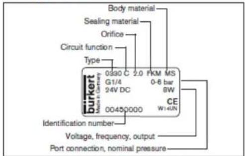
Fig. 1: Description of the type label (example)
8
english
6 ASSEMBLY

DANGER!
Risk of Injury from high pressure in the system/device.
Before working on the system or device, switch off the pressure and vent/drain lines.
Risk of injury due to electrical shock.
Before working on the system or device, switch off the power supply and secure to prevent reactivation.
- Observe applicable accident prevention and safety regulations for electrical equipment.

WARNING!
Risk of Injury from Improper assembly.
- The assembly may be carried out only by trained technicians and with the appropriate tools.
- Secure system against unintentional activation.
- Following assembly, ensure a controlled restart.
6.1 Before Installation
Installation position:
The installation position is optional. Preferably: Actuator at the top.
→ Prior to installation check pipelines for dirt and clean if necessary.
Dirt filter: To ensure that the solenoid valve functions reliably, a dirt filter ( ≤ 500 m) must be installed in front of the valve input.
6.2 Installation
→ Observe flow direction:
Functioning of the device is only ensured if the circuit function is maintained.
Devices in socket model
→ Use PTFE tape as sealing material.
→ Determine the maximum screw-in depth of the connecting threads as this does not comply with any standard.
NOTE!
Caution risk of breakage.
- Do not use the coil as a lifting arm.
→ Hold the device with a suitable tool (open-end wrench) on the body; screw into the pipeline.
Attaching the device:
→ Via bore holes M4x8 (made from brass or stainless steel) or self-tapping screws 3.9 DIN 7970 (made from plastic, max. screw-in depth 10 mm) on the bottom side of the body at drill pattern 38x24.
Devices in flange model
Attaching the device:
→ Via supplied screws on basic devices or manifold.
→ Tighten fastening screws on the coil to a maximum torque of 2 Nm.
english
9
6.3 Manual control
NOTE!
- When the manual control is locked, the valve cannot be actuated electrically.
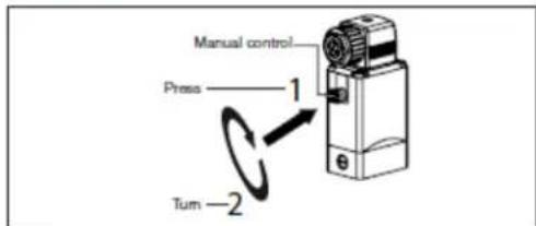
Fig. 2: Manual control
7 ELECTRICAL CONNECTION DANGER!
Risk of Injury due to electrical shock.
Before working on the system or device, switch off the power supply and secure to prevent reactivation.
- Observe applicable accident prevention and safety regulations for electrical equipment.
If the protective conductor is not connected, there is a risk of electric shock.
- Always connect protective conductor and check electrical continuity between coil and housing.

Fig 3: Connecting the cable plug to the power supply
Note the voltage and current type as specified on the type label.
10
english
Type 0121 / 0330 / 0331
7.1 Standard model
→ Connect L1/+ and N/- to terminals 1 and 2, independent of the polarity.
→ Connect protective conductor.
→ Attach seal and check for correct fit.
→ Tighten cable plug (Type 2508 or 2509 in accordance with DIN EN 175301-803 (DIN 43 650), shape A, for order numbers see data sheet); while doing so, observe the maximum torque of 1 Nm.
→ Check electrical continuity between coil and body (protective conductor function).
7.2 Pulse model (CF 02)
In accordance with the terminals on the valves, the connection terminals in the cable plug are marked with the numbers 1 to 3.
→ Connect as shown in "Fig. 4". Pulse on terminal 1 closes the valve; pulse on terminal 2 opens the valve.
→ Attach seal and check for correct fit.
→ Tighten cable plug (Type 2508 or 2509 in accordance with DIN EN 175301-803 (DIN 43 650), shape A, for order numbers see data sheet); while doing so, observe the maximum torque of 1 Nm.
→ Check electrical continuity between coil and body (protective conductor function).

Fig 4: Electrical connection - pulse model (CF 02)
NOTE!
▶ Prevent simultaneous pulsing on both coil windings.
- Parallel to the terminals, no other consumers (relay, etc.) may be connected.
- The respective coil connection that does not carry current must be galvanically isolated (open).
- In case two or more valves are connected in parallel, the use of two-pole or multi-pole switches must ensure that this requirement is met.
english
11
8 DISASSEMBLY

DANGER!
Risk of Injury from high pressure in the system/device.
Before working on the system or device, switch off the pressure and vent/drain lines.
Risk of injury due to electrical shock.
Before working on the system or device, switch off the power supply and secure to prevent reactivation.
- Observe applicable accident prevention and safety regulations for electrical equipment.

WARNING!
Risk of Injury from Improper disassembly.
- Disassembly may be carried out only by trained technicians and with the appropriate tools.
Risk of injury from hazardous media.
Before loosening lines or valves, flush out hazardous media, depressurize and drain the lines.
9 MAINTENANCE, TROUBLESHOOTING
9.1 Safety Instructions

DANGER!
Risk of Injury from high pressure in the system.
- Turn off the pressure and vent the lines before loosening lines or valves.
Risk of Injury due to electrical shock.
Before working on the system or device, switch off the power supply and secure to prevent reactivation.
- Observe applicable accident prevention and safety regulations for electrical equipment.

WARNING!
Risk of Injury from Improper maintenance work.
- Maintenance may be carried out only by trained technicians and with the appropriate tools.
- Secure system against unintentional activation.
- Following maintenance, ensure a controlled restart.
12
english
9.2 Malfunctions
If malfunctions occur, check whether:
→ the device has been installed according to the instructions,
→ the electrical and fluid connections are correct,
→ the device is not damaged.
→ all screws have been tightened,
→ the voltage and pressure have been switched on,
→ the pipelines are clean.
| Malfunction | Possible cause |
| Valve does not switch | Short circuit or coil interrupted |
| Medium pressure outside the permitted pressure range | |
| Manual control locked | |
| Valve does not close | Inner compartment of the valve is dirty |
| Manual control locked |
9.2.1 Repairs
Repairs may only be carried out by the manufacturer. Operating data may change if spare parts are replaced by the user.
10 TRANSPORTATION, STORAGE, DISPOSAL
NOTE!
Transport damage.
Inadequately protected devices may be damaged during transportation.
- Protect the device against moisture and dirt in shock-resistant packaging during transportation.
- Prevent the temperature from exceeding or dropping below the permitted storage temperature.
Incorrect storage may damage the device.
- Store the device in a dry and dust-free location.
▶ Storage temperature -40 - +80°C
Damage to the environment caused by parts contaminated with media.
- Dispose of the device and packaging in an environmentally friendly manner.
- Observe applicable disposal and environmental regulations.
english
13
english
english
english
english
english
(No text)
(No text)
(No text)
(No text)
(No text)
广力云智慧零售收银系统
english
english
english
english
english
english
english
english
english
(No text)
(No text)
(No text)
(No text)
(No text)
(No text)
(No text)
m = 311
(No text)
(No text)
(No text)
(No text)
-
-
-
-
-
PART 7: WARRANTY INFORMATION
OWNER'S LIMITED WARRANTY
Dometic Corporation (Dometic) warrants to the original purchaser/owner, and to subsequent owners during the applicable Limited Warranty Period, Dometic's Water Purification Products, Pumps, Related Accessories and Replacement Parts against failure from defects in material or workmanship arising in the periods specified in the Table of Limited Warranty Periods below. If a covered product or part fails during the applicable warranty period, Dometic will remedy same by repairing or replacing the defective warranted product or part as outlined below in the Table of Limited Warranty Periods. Defective parts shall be replaced free of charge and labor shall be paid for by Dometic only as set forth in the Table. Dometic reserves the right to refund the purchase price of the subject product or part as an alternative remedy to repair or replacement. The remedy allowed hereunder (repair, replacement or refund) shall be at Dometic's sole option.
SECTION I
WHAT'S COVERED
What does the Limited Warranty cover?
Water Purification Products, Pumps, Related Accessories and Replacement Parts manufactured and/or marketed by Dometic for the durations set forth in the Table of Limited Warranty Periods.
What is disclaimed, and are the warranties and remedies exclusive of all others?
Dometic does not disclaim the implied warranty of merchantability, but limits the duration of that implied warranty to the duration of the Limited Warranty offered herein.
This Limited Warranty, as well as the implied warranty of merchantability and the remedies offered by Dometic herein, are EXCLUSIVE and are made or provided in lieu of all other express or implied warranties, obligations, or liabilities. In no event shall Dometic be responsible or liable for any incidental or consequential damages alleged to have resulted from any defect in or failure of any warranted product or part. In those instances in which a cash refund is made, such refund shall effect the cancellation of the contract of sale and such refund shall constitute full and final satisfaction of all claims which the purchaser has or may have against Dometic due to any actual or alleged breach of warranty, either express or implied, including, without limitation, the implied warranty or merchantability or fitness for a particular purpose. Some states do not allow the exclusion or limitation of incidental or consequential damages so the above limitation may not apply to you. Some states do not allow limitations on how long an implied warranty lasts, so the above limitation may not apply to you.
The Dealer is not an agent for Dometic, except for the purpose of administering the above warranty to the extent herein provided. Dometic does not authorize the dealer or any other person to assume for Dometic any liability in connection with such warranty, or any liability or expense incurred in the replacement or repair of its products other than those expressly authorized herein. Dometic shall not be responsible for any liability or expense except as is specifically authorized and provided herein.
Dometic reserves the right to improve its products, through changes in design or material without being obligated to incorporate such changes in products of prior manufacture. Dometic can make changes at any time in design, materials, or part of units of any one, model year, without obligation or liability to owners of units of the same year's model of prior manufacture.
This warranty gives you, the purchaser/owner, specific legal rights, and you may also have other rights which vary from state to state.
OWNER'S LIMITED WARRANTY
SECTION II
WHAT'S NOT COVERED
What does this Limited Warranty not cover?
This Warranty Shall Not Apply to:
- Failures resulting from improper installation or use contrary to instructions.
- Failures resulting from abuse, misuse, accident, fire, or submergence.
- Any part manufactured by Dometic, which shall have been altered so as to impair its original characteristics.
- Any parts which fail as a result of misuse, improper application or improper installation.
- Items not manufactured by Dometic, i.e., items, which are purchased from another manufacturer and supplied as received by Dometic without alteration or modification except as any part of a Dometic manufactured unit or component.
- Components or parts used by or applied by the purchaser, as an integral part of products not manufactured by Dometic.
- Labor resulting from difficult access to a Dometic product. The original installer or OEM is responsible for accessibility of unit.
- Leaks due to improper installation of system, for example: hose clamps, fittings, flare nuts, quick disconnects.
- Freight Damage.
- Pumps that have been run dry, are water damaged or have blown freeze plugs.
- Pumps with cracked heads.
- Pump seals are not covered.
- UV light bulbs are not covered.
- Sea strainer elements are not covered.
- Cartridge filter elements are not covered.
- Sand & gravel in a multi-media filter are not covered.
- Pump packing assemblies are not covered.
- Pump valve assemblies are not covered.
- Pump crankcase oil is not covered.
- Gauge instrument calibration is not covered.
- Fuses are not covered.
- Valve seals and packings are not covered.
- Exterior corrosion is not covered.
- Membrane elements are not covered.
25 Logic boards with water damage. - Logic boards with blown MOV's (Power Surge)
- Mis-programmed displays.
- Displays or remotes with water damage.
- Failures due to improper winterization.
- Unit damage as a result of improper return packaging.
- Travel costs are included in the hourly labor allowances and should not be billed as a separate item without preapproval from the factory.
Installation and application of Dometic components are not warranted by Dometic, because Dometic has no control or authority over the selection, location, application, or installation of these components.
OWNER'S LIMITED WARRANTY
SECTION III
COVERAGE PERIOD
What is the period of coverage?
SEE TABLE OF LIMITED WARRANTY PERIODS BELOW.
How does one determine when the Limited Warranty Period begins? All Dometic products bear a data plate on which there are model and serial numbers. The date of manufacture of the product can be determined by Dometic based on the serial number on the product. To determine whether or not any Dometic component is in warranty, proceed as follows:
- Determine the model and serial number on the data plate located on the product. Write or call the Dometic Customer Service Department to obtain the manufacture date of the product. The hours of the Customer Service Department are 8:00 a.m. - 5:00 p.m. (USA, Eastern Standard Time Zone) Monday through Friday excluding holidays.
- It is possible that a considerable time lag exists between the date a product or component is manufactured and the date it is put in service. In such instances, the date of manufacture could indicate that the item is out of warranty. However, based on the date the equipment is first put in service, the item may still be covered by the Dometic Limited Warranty. For proof of date put in service, Dometic will require a copy of the bill of sale of the Dometic equipment from the installer or new boat dealer to the original owner.
OWNER'S LIMITED WARRANTY
SECTION IV
GETTING COVERED WARRANTY SERVICE
How does the purchaser/owner get warranty service?
Please read the following Warranty Procedure: If the failure of a Dometic component is determined to be covered under the Dometic warranty and the time in service is determined to be within the warranty time limit, the owner has the following three options:
-
Preferred option: Have a Dometic authorized Servicing Dealer, perform the work needed. The customer needs to call Dometic Customer Service Department for a recommendation as to the closest dealer. If the customer already knows an authorized servicing dealer, the dealer should be contacted directly.
-
Second option: If the customer contacts Dometic Service Department for a Servicing Dealer and Dometic has no one in that particular area, Dometic will authorize the use of a local service company and Dometic will work with the local company to assist in any way possible.
The customer may contact the Dometic Service Department at 1(800) 542-2477, Monday through Friday, 8:00am - 5:00pm.
TABLE OF LIMITED WARRANTY PERIODS
Important Notes Regarding Product Start-up/ Commissioning:
-
Warranty periods begin from the date of possession of the boat/vessel by the first owner if OEM installed or date of installation if dealer installed, but not to exceed three (3) years from date of production of the product. However, if the product is started for any reason by the OEM or dealer, notwithstanding any provision to the contrary, the warranty period will be for a period of one (1) year commencing from the date that the product was started by the OEM or dealer. The warranty is transferable and will carry the remainder of the original owner's warranty based on the original date of purchase or date of installation.
-
Proof of purchase or installation may be required to verify warranty coverage.
-
Any unit or replacement part installed due to a warranty failure carries the remainder of the original warranty. Warranty coverage does not start over from the repair/replacement date.
-
Warranty coverage shall not exceed three (3) years from the date of production of the product.
-
These warranty periods are effective February 1, 2014.
WATER PURIFICATION PRODUCTS:
PRODUCT SALE TYPE WARRANTY COVERAGE
Spot Zero OEM 1-year warranty, parts and labor, from date of delivery of vessel. Not to exceed 3 years from date of production of product, and subject to Important Notes above. Pump warranty, see Pump section.
Dealer Installed 1-year warranty, parts and labor, from date of installation. Not to exceed 3 years from date of production of product, and subject to Important Notes above. Pump warranty, see Pump section.
Sea Xchange OEM 1-year warranty, parts and labor, Not to exceed 3 years from date of production of product, and subject to Important Notes above. Pump warranty, see Pump section.
Dealer Installed 1-year warranty, parts and labor, from date of installation. Not to exceed 3 years from date of production of product, and subject to Important Notes above. Pump warranty, see Pump section.
(SE SERIES, SX SERIES FROM DATE OF DELIVERY OF VESSEL. XTC SERIES, CX SERIES)
PUMPS, ACCESSORIES, REPLACEMENT PARTS:
PRODUCT SALE TYPE WARRANTY COVERAGE
Pumps OEM or Dealer Installed 1 year warranty, parts and labor. Wearable parts such as pump seals, brushes and plastic valves are not covered under warranty.
SECTION IV (CONTINUED)
Dealer Installed and 1 year warranty, parts only. Wearable parts such as pump seals, brushes and plastic valves are not covered under warranty.
Accessories OEM, Dealer Installed, 1 year warranty, parts only.
Replacement Parts Aftermarket sales. 90-Day warranty, parts only.
This Page Intentionally Left Blank
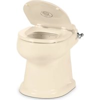

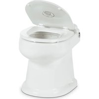
- TABLE OF CONTENTS
- INTRODUCTION 4
- INSTALLATION AND COMMISSIONING....14
- TROUBLESHOOTING .... 50
- PARTS....56
- MANUFACTURER'S INDEX 74
- WARRANTY INFORMATION...... 120
- PART 1: INTRODUCTION
- CONGRATULATIONS
- SAFETY
- PRINCIPLES OF REVERSE OSMOSIS
- REVERSE OSMOSIS
- How Fresh Water Is Produced
- Osmosis
- OPERATION SPECIFICATIONS
- BEFORE STARTING
- PRE-FILTRATION
- BOOSTER PUMP
- HIGH PRESSURE PUMP
- MEMBRANES
- DIVERSION VALVE
- SYSTEM CONTROLLER
- PRODUCT WATER
- Rejection
- Recovery
- TEMPERATURE CORRECTION FACTORS FOR WATER PRODUCTION
- TEMPERATURE CORRECTION FACTORS FOR MEMBRANE (FORMULA)
- Example:
- PART 2: INSTALLATION AND COMMISSIONING
- INSTALLATION KIT
- ITEMS INCLUDED WITH EACH SYSTEM
- MAIN INSTALLATION ITEMS
- CONSUMABLE ITEMS
- OPTIONAL ITEMS
- DIMENSIONS
- MOUNTING
- ELECTRICAL REQUIREMENTS
- ELECTRICAL
- PLUMBING AND PIPING CONNECTIONS
- PLUMBING
- SYSTEM LAYOUT AND SCHEMATICS
- COMPLETE INSTALL GUIDE
- SEA WATER PLUMBING CONNECTIONS
- NOTE - BOOSTER PUMP OUTLET MUST REMAIN THE HIGHEST POINT OF PUMP AND CANNOT BE ROTATED 90 OR 180 DEGREES.
- PRODUCT TO TANK CONNECTION
- FRESH WATER FLUSH CONNECTION
- ELECTRICAL CONNECTIONS
- NEW SYSTEM START-UP
- INSPECTION
- SYSTEM PURGE
- SEA XCHANGE COMMISSIONING REPORT FORM
- NORMAL OPERATION
- START-UP
- Note:
- SHUTDOWN
- FRESHWATER FLUSH
- OPERATIONAL DO'S AND DON'Ts
- DO \_
- DON'T
- FRESH WATER FLUSH
- AUTOMATIC FRESH WATER FLUSH
- MANUALLY FLUSHING THE SYSTEM (Manual Bypass on solenoid)
- STORAGE OR WINTERIZATION OF UNIT
- Option 1: Storage with Fresh Water Flush
- Option 2: Storage without Fresh Water Flush:
- Option 3: Winterization
- Re-commissioning of System after Storage or Winterization
- MEMBRANE REMOVAL AND REPLACEMENT
- REMOVAL AND REPLACEMENT
- NOTE: WEAR GLOVES FOR THE FOLLOWING STEPS IN ORDER NOT TO CONTAMINATE THE MEMBRANE.
- HIGH PRESSURE PUMP OIL CHANGE
- OIL CHANGE STEPS
- PART 4: TROUBLESHOOTING
- ABNORMAL PRODUCT FLOW
- PRESSURE SWITCH ADJUSTMENT
- NOTE: THE SWITCH ADJUSTMENT STEPS ARE THE SAME FOR BOTH LP AND HP SWITCHES
- BY-PASS
- NOTE!
- PART 5: PARTS
- PART 6: MANUFACTURERS INDEX
- Conductivity Probe Calibration
- Controller Fault Condition Displays
- GENERAL HIGH PRESSURE PUMP
- WM Series
- SERVICING PUMP PROCEDURES
- To service any valve:
- WM Series Servicing Instructions
- Replacing packings using kit WM02:
- Recommended Tools/Supplies:
- MAINTENANCE LOG
- INSTALLATION, OPERATING AND MAINTENANCE MANUAL
- TYPE HP CENTRIFUGAL PUMPS
- MODELS:HP75 CN/CS, BN/BS, KN/KS, NN HP75 SS/SC, AB HP100 SS/SC, AB
- RECOMMENDED PRECAUTIONS
- READ CAREFULLY THE CAUTION BELOW
- INSTALLATION / OPERATING INSTRUCTIONS CENTRIFUGAL PUMPS
- Warning
- Do not ground to gas supply line!
- Close Coupled Motor Pumps
- Power Frame Mounted Pumps
- Direction of Rotation
- Suction Piping (Inlet)
- Discharge Piping (Outlet)
- Operation
- TYPE HP MAINTENANCE AND REPAIR
- DISASSEMBLY
- REASSEMBLY
- For Type 6, 8, 9 and 21 seals:
- T6 seal only:
- T21 only:
- T 8 & 9 only:
- Volute Bolt Torque Specifications
- INSTALLING A PEO (PUMP END ONLY) STUB SHAFT PUMP
- INSTALLING A PEO (PUMP END ONLY) NON-STUB SHAFT PUMP
- PRICE®PUMP CO.
- PRICE PUMP CO.
- PRICE CENTRIFUGAL PUMP CAUTIONS & WARNINGS
- DOW FILMTEC™ MEMBRANES
- Features
- Operating Limits
- Important Information
- Operation Guidelines
- General Information
- BURKERT DIVERSION VALVE
- THE OPERATING INSTRUCTIONS
- Symbols
- DANGER!
- WARNING!
- CAUTION!
- english
- Definitions of terms
- AUTHORIZED USE
- Only operate the device
- Restrictions
- BASIC SAFETY INSTRUCTIONS
- General hazardous situations.
- SYSTEM DESCRIPTION
- General description
- TECHNICAL DATA
- Conformity
- Standards
- Operating conditions
- Mechanical data
- Fluidic data
- Electrical data
- ASSEMBLY
- Before Installation
- Installation
- Devices in socket model
- Devices in flange model
- Manual control
- ELECTRICAL CONNECTION DANGER!
- Standard model
- Pulse model (CF 02)
- DISASSEMBLY
- MAINTENANCE, TROUBLESHOOTING
- Safety Instructions
- Malfunctions
- TRANSPORTATION, STORAGE, DISPOSAL
- PART 7: WARRANTY INFORMATION
- OWNER'S LIMITED WARRANTY
- SECTION I
- WHAT'S COVERED
- SECTION II
- WHAT'S NOT COVERED
- What does this Limited Warranty not cover?
- This Warranty Shall Not Apply to:
- SECTION III
- COVERAGE PERIOD
- SECTION IV
- GETTING COVERED WARRANTY SERVICE
- How does the purchaser/owner get warranty service?
- TABLE OF LIMITED WARRANTY PERIODS
- Important Notes Regarding Product Start-up/ Commissioning:
- WATER PURIFICATION PRODUCTS:
- PRODUCT SALE TYPE WARRANTY COVERAGE
- PUMPS, ACCESSORIES, REPLACEMENT PARTS:
- SECTION IV (CONTINUED)
Brand : DOMETIC
Model : SeaXchange SE 800
Category : Toilet