4310 - Toilet DOMETIC - Free user manual and instructions
Find the device manual for free 4310 DOMETIC in PDF.

| Product Type | Gravity flush toilet in vitreous china |
| Brand | Dometic |
| Model | 4310 |
| Dimensions (L x W x H) | 483 x 376 x 940 mm |
| Approximate weight | 25 kg |
| Power supply | 12 V DC, 2 A fuse or circuit breaker |
| Water supply connection | 1/2 in NPT, minimum flow rate 9.5 L/min |
| Discharge | 4-bolt floor flange, 77 mm (3 in) I.D., gravity drain |
| Bowl material | Vitreous china |
| Flush handle | Plated brass |
| Included parts | Toilet, discharge adapter fittings, floor mounting hardware, template |
| Optional accessories | Tank level controller DTM01C, DTM04 |
| Installation | By a qualified professional, follow local codes |
| Safety | Risk of electric shock, fire, flooding or explosion. Use genuine Dometic parts |
| Care and cleaning | Clean with a mild non-abrasive detergent |
| Limited warranty | See www.dometic.com/warranty |
Frequently Asked Questions - 4310 DOMETIC
User questions about 4310 DOMETIC
0 question about this device. Answer the ones you know or ask your own.
Ask a new question about this device
Download the instructions for your Toilet in PDF format for free! Find your manual 4310 - DOMETIC and take your electronic device back in hand. On this page are published all the documents necessary for the use of your device. 4310 by DOMETIC.
USER MANUAL 4310 DOMETIC
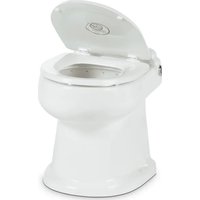
natural_image
Line drawing of a standard toilet with handle and seat (no text or symbols)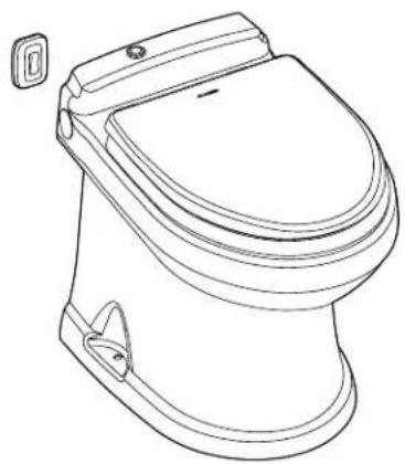
natural_image
Line drawing of a standard open-toe toilet with lid and side door (no text or symbols)
natural_image
Line drawing of a standard open toilet (no text or symbols)4300/4400/6500
EN Full Ceramic Gravity Discharge Toilet
Installation Manual....2
Read these instructions carefully.
These instructions MUST stay with this product.
Contents
1 Explanation of Symbols and Safety Instructions .... 3
1.1 Recognize Safety Information .... 3
1.2 Understand Signal Words....3
1.3 Supplemental Directives....3
1.4 General Safety Messages .... 3
2 Intended Use.... 4
3 General Information....4
3.1 Materials 4
3.2 Wiring Diagram 4
3.3 Specifications 5
4 Pre-Installation 6
4.1 Laying Out the Fresh-Water System ..... 6
4.2 Planning the Electrical Connections.....7
5 Installation....7
5.1 Preparing the Toilet Location ..... 7
5.2 Installing the Discharge Flange.....8
5.3 Installing the Floor Brackets ..... 8
5.4 Routing the Power and Water Lines ..... 9
5.5 Installing the "Full Tank" Shut-Down Relay and Tank Monitor System . . 9
5.6 Finalizing the Installation....9
6 Disposal....11
LIMITED WARRANTY ....11
Customer Support....24
1 Explanation of Symbols and Safety Instructions
This manual has safety information and instructions to help you eliminate or reduce the risk of accidents and injuries.
1.1 Recognize Safety Information

This is the safety alert symbol. It is used to alert you to potential physical injury hazards. Obey all safety messages that follow this symbol to avoid possible injury or death.
1.2 Understand Signal Words
A signal word will identify safety messages and property damage messages, and will indicate the degree or level of hazard seriousness.

DANGER!
Indicates a hazardous situation that, if not avoided, will result in death or serious injury.

WARNING
Indicates a hazardous situation that, if not avoided, could result in death or serious injury.

CAUTION
Indicates a hazardous situation that, if not avoided, could result in minor or moderate injury.
NOTICE: Used to address practices not related to physical injury.
Indicates additional information that is not related to physical injury.
1.3 Supplemental Directives
To reduce the risk of accidents and injuries, please observe the following directives before installing this appliance:
- Read and follow all safety information and instructions to avoid possible injury or death.
- Read and understand these instructions before installation of this product.
- The installation must comply with all applicable local or national codes, including the latest edition of the following standards:
U.S.A.
- ANSI/NFPA70, National Electrical Code (NEC)
- ANSI/NFPA 1192, Recreational Vehicles Code
- ABYC guidelines for marine installations
Canada
- CSA C22.1, Parts I & II, Canadian Electrical Code
– CSA Z240 RV Series, Recreational Vehicles
1.4 General Safety Messages

WARNING: ELECTRICAL SHOCK, FIRE, FLOOD, AND/OR EXPLOSION HAZARD.
Failure to obey the following warnings could result in death or serious injury:
- Use only Dometic replacement parts and components that are specifically approved for use with the appliance.
- This product must be installed and serviced by a qualified service technician.
- Do not modify this product in any way. Modification can be extremely hazardous.
- For marine applications, seacocks must be installed in all piping connected to through-the-hull fittings. Seacocks must be easily accessible to all users of the toilet, or secondary valves should be fitted in hose runs where they are easily accessible.
- For marine applications, if the toilet is connected to any through-the-hull fittings, always close the seacocks when the toilet is not in use (even if unattended for a brief period).
- For marine applications, valves must be full-bore valves of marine sanitation quality. Do not use screw-to-close gate valves.
-
If the toilet uses fresh water for flushing and is connected directly or indirectly to a municipal water system at any time, the water connections must be discon nected if the boat or RV is unattended (even if unattended for a brief period).
-
Ensure that all electrical power to the toilet is turned off, and for marine applications, ensure that seacocks are in the closed or off position before installing the toilet or performing any maintenance.
- For marine applications, if the toilet is connected to any through-the-hull fittings, all flexible hoses must be of marine sanitation quality and must be secured to any fittings (such as those at the seacock, vented loop, or toilet) with two stainless steel, worm-drive, hose-band clamps at each connection. Check the connections frequently for integrity.
- For marine applications, use properly positioned, ventilated loops when the potential exists for the toilet rim to fall below the waterline during any heel, load, or trim condition, or when the toilet is connected to any through-the-hull fittings. The ventilated loops must be installed in the intake (if connected to raw water) and/or the discharge piping.
- For marine applications, if the toilet uses raw water for flushing at any time, a raw-water pump controlled by an automatically operating demand switch must not be installed. If the onboard water valve or any plumbing connections were to leak, the automatically operated pump would start and could flood the boat or RV.
2 Intended Use
The 4300, 4400, and 6500 series toilets are designed and intended for use only inside the boat or recreational vehicle (hereinafter referred to as "RV") for which it is supplied. Use these instructions to ensure correct installation of the toilet. Dometic Corporation accepts no liability for damage in the following cases:
- Faulty assembly or connection
- Damage to the product resulting from mechanical influences and excess voltage
• Alterations to the product without expressed permission from Dometic Corporation - Use for purposes other than those described in the operating manual
Dometic Corporation reserves the right to modify appearances and specifications without notice.
3 General Information
This section provides reference information on the tooling, wiring, and specifications associated with the toilet series.
The images used in this document are for reference purposes only. Components and component locations may vary according to specific product models. Measurements may vary ±0.38 in. (10 mm).
Included Parts
| Toilet |
| Discharge adapter fittings |
| Floor mounting hardware kit |
| Floor-mounting template |
Optional Parts ^1
| DTM01C tank monitor |
| DTM04 four-level tank monitor |
^1 Available as an accessory (not included)
3.1 Materials
This section outlines the toilet component materials.
Component Material
| Toilet Vitreous ceramic |
| Dometic switch (4400 only) Various plastics and metal |
| Touch panel (6500 only) Various plastics and metal |
| Flush handle (4300 only) Plated brass |
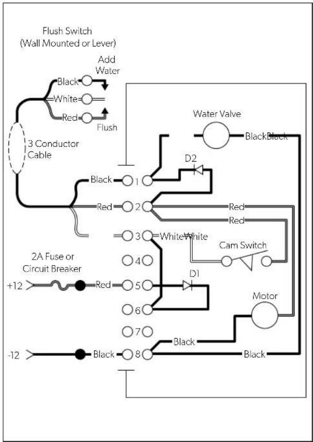
3.2 Wiring Diagram
Figure 1 provides an example of the 4300/4400 toilet wiring specifications.
For the 6500 toilet series, refer to the separately packaged parts list for wiring information.
flowchart
graph TD
    A["3 Conductor Cable"] --> B["Add Water"]
    B --> C["Black"]
    B --> D["White"]
    B --> E["Red"]
    B --> F["Flush"]
    G["2A Fuse or Circuit Breaker"] --> H["+12"]
    G --> I["Red"]
    G --> J["5"]
    G --> K["6"]
    G --> L["7"]
    G --> M["8"]
    N["Water Valve"] --> O["Black"]
    P["Cam Switch"] --> Q["D1"]
    R["Motor"] --> S["Black"]
    T["Black"] --> U["+12"]
    V["Black"] --> W["-12"]
    X["White"] --> Y["3"]
    Z["White"] --> AA["4"]
    AB["White"] --> AC["5"]
    AD["White"] --> AE["6"]
    AF["White"] --> AG["7"]
    AH["White"] --> AI["8"]
1 4300/4400 Wiring Diagram
3.3 Specifications
This section provides reference information on the system requirements, and dimensions associated with the toilet series.
3.3.1 Dimensions
Figure 2 and Figure 3 show the relevant dimensions for each toilet series.
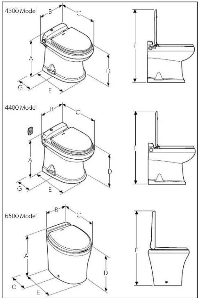
2 Toilet Dimensions
| Ref 6500 Series | 4300 Series (w/flush handle) | 4400 Series (w/wall-mounted flush switch) | ||||
| in. mm | in. mm | in. mm | ||||
| A | 19.0 | 483 | 19.0 | 483 | 19.0 | 483 |
| B | 14.8 | 376 | 15.8 | 402 | 14.8 | 376 |
| C | 22.0 | 559 | 21.5 | 547 | 21.5 | 547 |
| D | 17.5 | 445 | 17.8 | 453 | 17.8 | 453 |
| E | 17.5 | 445 | 17.1 | 435 | 17.1 | 435 |
| F | 37.0 | 940 | 33.8 | 859 | 33.8 | 859 |
| G | 11.0 | 280 | 11.0 | 280 | 11.0 | 280 |
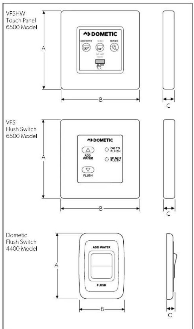
3 Panel and Control Module Dimensions
| Measurements | |||||
| A B C | |||||
| Model in. mm in. mm in. mm | |||||
| 6500 3.0 | 77 | 3.5 | 89 | 0.4 | 11 |
| 4400 2.85 | 73 | 1.85 | 47 | .63 | 16 |
3.3.2 Minimum System Requirements
Dometic recommends that the toilet installation meet the following minimum requirements:
| Component | Minimum Requirement |
| Electrical | |
| Circuit breaker | 2 A/12 VDC; 1 amp/24 VDC |
| Wiring | Marine: Refer to ABYC recommendations.RV: Refer to ANSI/RVIA LV and NFPA 70/NEC Standards (USA), or CEC I and IIStandards (Canada) for recommended wire gauge sizes. |
| Water Supply | |
| Fitting | 0.5 in. (13 mm) NPT |
| Flow rate | 2.5 gpm/9.5 lpm minimum at toilet |
| Discharge | |
| Fitting | 4-bolt floor (closet) flange, 3.0 in. (77 mm) ID, ABS or PVC connection to holding tank, gravity drain |
Refer to ANSI 1192 and Z240 RV Series standards, where applicable, for additional RV toilet installation guidelines. Specifications are subject to change without notice.
4 Pre-Installation
WARNING: SHOCK OR FIRE HAZARD.
Use the recommended fuse, circuit breaker, and wire size. Failure to obey this warning could result in death or serious injury.
This section has information on the preparation work required prior to the toilet installation.
4.1 Laying Out the Fresh-Water System
Figure 4 shows the recommended fresh-water system layout for the gravity discharge toilets.
Use cold water only. Install a shut-off valve in the water line for maintenance purposes.
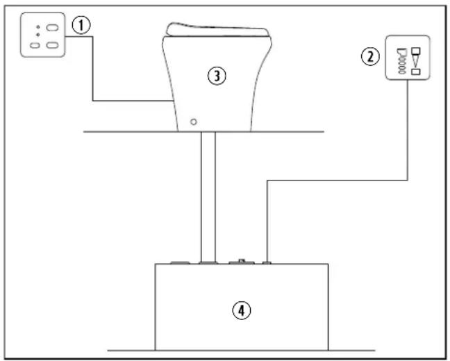
4 Fresh-Water System Diagram
① Flush Switch/Status Panel
③ Gravity Toilet
② Holding Tank Status Panel
④ Holding Tank
4.2 Planning the Electrical Connections
Read before proceeding:
- There must be a circuit breaker or fuse for every toilet control. Make sure the power supply is turned off during installation.
- For marine applications, follow ABYC guidelines.
- For RV applications, refer to ANSI/RVIA LV and NFPA70/NEC standards (U.S.A.) or CEC I and II standards (Canada) for the recommended wire gauge. Refer to "1.3 Supplemental Directives" on page 3.
- Use tinned, stranded-copper wire.
- Use crimp-type wire connections. Do not use wire nuts, as wire nuts can corrode.
Plan all component locations so that the wires are installed in locations that will always remain dry.
Several flush assembly options are available from Dometic. Follow the instructions included with each flush assembly.
EN
5 Installation
This section describes how to install the toilets.
5.1 Preparing the Toilet Location
This section describes how to use the toilet templates to identify and cut the required connection holes.
Not all toilet models have templates. Alternative instructions are provided for the models that do not have templates. This installation uses through-the-floor connections.
1. Mark the hole locations.
- For 4300 and 4400 series: no template is provided for these models. Refer to Figure 5 for hole locations.
-
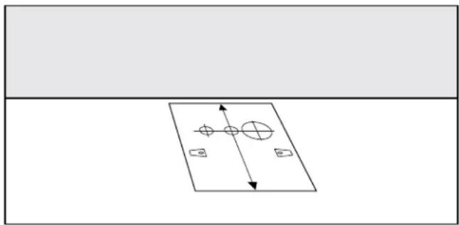
For the 6500 series:
-
Place the floor-mounting template in the desired location. Keep at least 11.0 in. (280 mm) between the centerline of the template and any walls or interior fixtures. Refer to Figure 6.
– Punch through the center of the holes and floor-bracket corners in the template. - Remove the template from the floor.
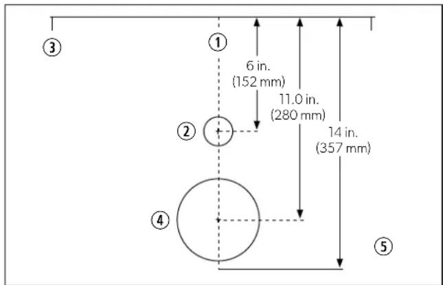
5 4300 and 4400 Series: Toilet Hole Locations
① Centerline
③ Rear Corner of Bowl
② Water Supply Line & Electrical Wire Access Hole
④ Discharge Flange Access Hole
⑤ Floor
natural_image
Simple diagram with a rectangular plane and directional arrows, no text or symbols present6 6500 Series: Mounting Template
2. Drill all access and fastener holes, except the discharge hole, as appropriate to your installation, using the center punches as guides.
3. Repeat these steps using the wall switch template (included in wall switch manual). Drill a 1.0 in. (25 mm) diameter hole.
5.2 Installing the Discharge Flange
This section describes how to install the discharge flange.
- Determine your installation option before cutting the discharge hole.
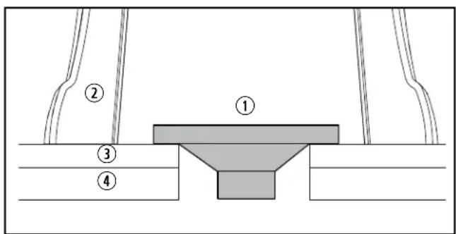
7 Preferred Floor Flange Installation Option
① Floor Flange
③ Floor
② Toilet Base
④ Sub-Floor
The space between the bottom of the toilet base and the bottom of the floor flange rim should be no greater than 0.38 in. (10 mm).
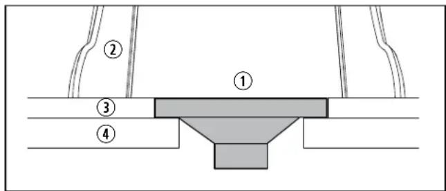
8 Below-Floor Installation
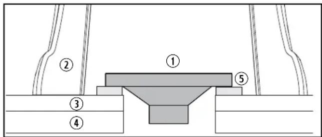
9 Above-Floor Installation
① Floor Flange
④ Sub-Floor
② Toilet Base
⑤ Spacer
③ Floor
- Cut out the discharge hole.
Confirm your flange size before cutting. Make a 4.75 in. (121 mm) discharge flange hole for most floor flanges. Some flanges will require a larger diameter hole. A 5.125 in. (131 mm) hole is recommended for swivel joint flanges.
- Insert the floor flange into the discharge hole and secure the flange to the floor using #12 x 3/4 in. (19 mm) flat-head wood or sheet metal screws.
5.3 Installing the Floor Brackets
6500 Series Only
This section describes how to secure the floor brackets that hold the toilet in place.
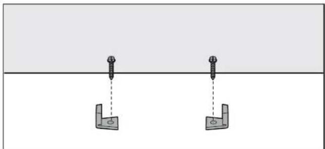
natural_image
Diagram showing two identical mechanical components with bolt holes, suspended from a horizontal surface (no text or symbols)10 Floor Bracket Placement
-
Secure the floor brackets to the floor using the long hex-head screws from the toilet floor-bracket kit.
-
Loosely tighten with a 3/8 in. (9.6 mm) socket wrench, using the floor bracket corner marks as guides.
Do not completely tighten the hex-head screws to the floor. Brackets will tighten when securing the toilet.
5.4 Routing the Power and Water Lines
This section explains how to route the power and water lines for connection to the toilet.
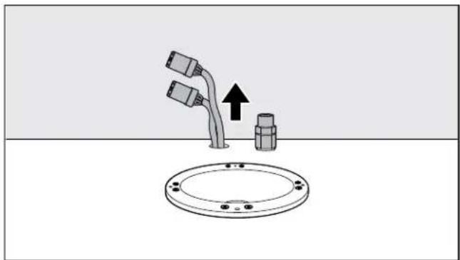
natural_image
Diagram showing a pipe connection with two connectors and a valve, above a circular base (no text or symbols)11 Wiring and Water Line Placement
-
Route the DC power wiring and 0.5 in. (13 mm) diameter water line through the drilled holes, as applicable.
-
Place a shut-off valve in the water line to the toilet to allow for easier maintenance or repair needs.
Refer to "4.2 Planning the Electrical Connections" on page 7, and to the wiring diagram provided with the toilet model's parts list. Wiring configuration varies by model.
EN
5.5 Installing the "Full Tank" Shut-Down Relay and Tank Monitor System
All installations can be set up to include the "full tank" shut-down relay and tank monitor system options.
Consult the wiring diagrams included with the toilet for further details. Wiring associated with these options needs to be done prior to the next step.
-
Route the wiring for the "full tank" option per the wiring diagram included with the toilet.
-
Proceed to "5.6 Finalizing the Installation" on page 9.
5.6 Finalizing the Installation
This section provides the final connections, placement, and fastening details for securing the toilet in place.
5.6.1 Connecting the Toilet Lines
This section explains how to connect the power and water lines to the toilet.
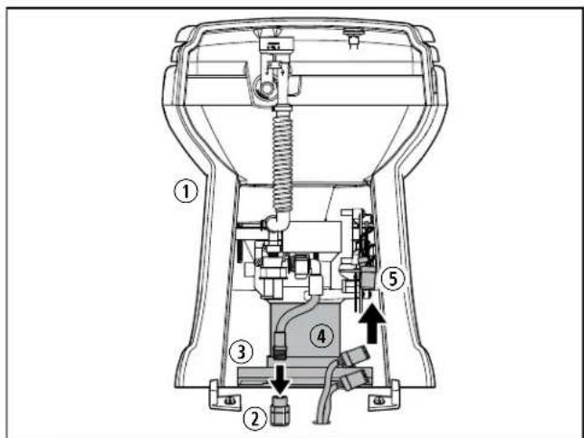
12 Final Toilet Connection Points (6500 Series: Rear View)
① Toilet
④ Plastic base
② Water supply connection
⑤ Wiring
③ Discharge assembly
-
Place the toilet near the access holes.
-
Connect the toilet water line to the water supply line.
-
Connect the touch panel or flush-switch panel wires to the toilet wiring, as applicable.
5.6.2 Placing the Toilet
This section describes how to place the toilet over the discharge assembly before securing it to the floor.
- Lubricate the O-ring around the bottom of the toilet base, using liquid dish-washing soap.
- Pick up the toilet and insert the plastic base into the discharge assembly. Do not slide the toilet over the assembly.
For the 6500 series: make sure the floor brackets do not interfere with the bottom of the toilet. - Turn on the water supply and power to the toilet controls, as applicable.
- Check for leaks by flushing the toilet, filling it to the appropriate level, and waiting for one hour to see if the toilet leaks. See your applicable toilet operation manual for details. If there is a leak, tighten the connections.
5.6.3 Securing the 4300 and 4400 Series Toilets
This section explains the final steps to secure the 4300 and 4400 series toilets. For information on securing the 6500 series toilets, refer to "5.6.4 Securing the 6500 Series Toilets" on page 10.
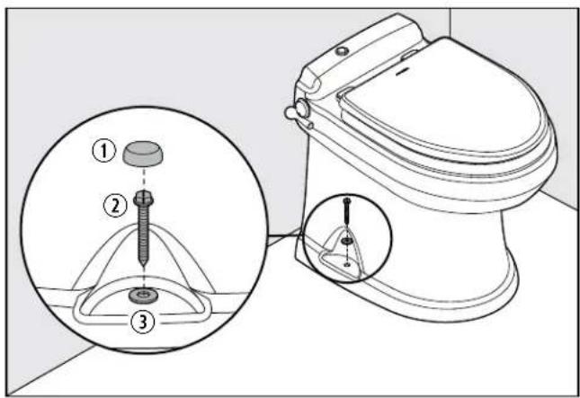
13 4300 and 4400 Series: Toilet Connection Points
① Cover
③ Washer
② Screw
-
Drill pilot holes at the floor-mounting holes.
-
Install the screws and washers (provided) using a 3/8 in. (9.6 mm) socket wrench.
- Place the plastic covers over the screws
5.6.4 Securing the 6500 Series Toilets
This section explains the final steps to secure the 6500 series toilets. For information on securing the 4300 and 4400 series toilets, refer to "5.6.3 Securing the 4300 and 4400 Series Toilets" on page 10.
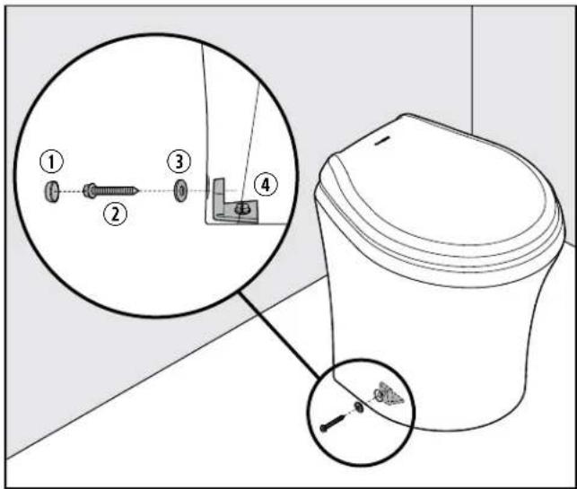
14 6500 Series: Toilet Connection Points
① Cover
③ Washer
② Screw
④ Floor Bracket
- Insert the plastic washers from the floor-bracket kit into the fastener holes.
- Fasten the toilet to the floor-brackets using the short screws included with the floor-bracket kit.
- Place the plastic covers over the floor-bracket screws.
6 Disposal
Place the packaging material in the appropriate recycling waste bins, whenever possible. Consult a local recycling center or specialist dealer for details about how to dispose of the product in accordance with all applicable national and local regulations.
LIMITED WARRANTY
LIMITED WARRANTY AVAILABLE AT WWW.DOMETIC.COM/WARRANTY.
IF YOU HAVE QUESTIONS, OR TO OBTAIN A COPY OF THE LIMITED WARRANTY FREE OF CHARGE, CONTACT:
DOMETIC CORPORATION SANITATION CUSTOMER SUPPORT CENTER 13128 STATE ROUTE 226 BIG PRAIRIE, OHIO, USA 44611 1-800-321-9886
Lire attentivement ces instructions. Ces instructions
5 Installation....17
Customer Support.....24
natural_image
Simple diagram with a rectangular shape containing three circles and directional arrows, no text or symbols present.natural_image
Two identical mechanical bracket diagrams with bolt holes, suspended from a horizontal line (no text or symbols)natural_image
Diagram showing a pipe with two connectors and a valve, above a circular base with mounting holes (no text or symbols)For the Authorized Service Center near you, call between 8:00 a.m. and 5:00 p.m., Monday through Friday, or contact the nearest Parts Distributor. Hours may vary.
DOMETIC
www.dometic.com
Dometic Sanitation Division
Customer Support Center
13128 St. Rte. 226
Big Prairie, OH 44611
+1 800-321-9886 (USA and Canada)
+330-439-5550(International)
+330-496-3097(USA and Canada)
+330-439-5567(International)
AUSTRALIA
Dometic Australia Pty. Ltd.
1 John Duncan Court
Varsity Lakes QLD 4227
1800212121
昌+61755076001
Mail: sales@dometic.com.au
AUSTRIA
Dometic Austria GmbH
Neudorferstraße 108
A-2353 Guntramsdorf
+43 2236 908070
吕+43223690807060
Mail: info@dometic.at
BENELUX
Dometic Branch Office Belgium
Zincstraat 3
B-1500 Halle
+32 2 3598040
吕+32 2 3598050
Mail: info@dometic.be
BRAZIL
Dometic DO Brasil LTDA
Avenida Paulista 1754, conj. 111
SP 01310-920 Sao Paulo
+551132513352
马+551132513362
Dometic Group Asia Pacific
Suites 2207-11 · 22/F · Tower 1
The Gateway · 25 Canton Road,
Tsim Sha Tsui · Kowloon
+85224611386
+852 2 4665553
Mail: info@waeco.com.hk
HUNGARY
Dometic Zrt. Sales Office
Kerékgyártó u. 5
H-1147 Budapest
+3614684400
+3614684401
Domettic Italy S.r.l.
Via Virgilio, 3
I-47122 Forlì (FC)
+39 0543 754901
品+390543754983
Mail: vendite@dometic.it
JAPAN
Dometic KK
Maekawa-Shibaura, Bldg. 2
2-13-9 Shibaura Minato-ku
Tokyo 108-0023
+81 3 5445 3333
+81354453339
Mail: info@dometic.jp
MEXICO
Circuito Médicos No. 6 Local
Colonia Ciudad Satélite
CP 53100 Naucalpan de Juárez
Estado de México
+52 55 5374 4108
+52 55 5393 4683
Mail: info@dometic.com.mx
NETHERLANDS
Dometic Benelux B.V.
Ecustraat 3
NL-4879 NP Etten-Leur
+31 76 5029000
日+31765029019
Mail: info@dometic.nl
NEW ZEALAND
Dometic New Zealand Ltd.
PO Box 12011
Penrose
Auckland 1642
16496221490
+6496221573
Mail: customerservices@dometic.co.nz
NORWAY
Dometic Norway AS
∅sterøyveien 46
N-3232 Sandefjord
+47 33428450
14733428459
Mail: firmapost@dometic.no
POLAND
Dometic Poland Sp. z o.o.
Ul. Puławska 435A
PL-02-801 Warszawa
+48 22 414 3200
+48 22 414 3201
Mail: info@dometic.pl
PORTUGAL
Dometic Spain, S.L.
Komsomolskaya square 6-1
RU-107140 Moscow
+7 495 780 79 39
+7 495 916 56 53
Mail: info@dometic.ru
SINGAPORE
Dometic Pte Ltd
18 Boon Lay Way 06-140 Trade Hub 21
Singapore 609966
+65 6795 3177
+65 6862 6620
Mail: dometic@dometic.com.sg
SLOVAKIA
Dometic Slovakia s.r.o. Sales Office
Bratislava
Nádražná 34/A
900 28 Ivánka pri Dunaji
円/目 +421245529680
Mail: bratislava@dometic.com
SOUTH AFRICA
Dometic (Pty) Ltd.
Regional Office
South Africa & Sub-Saharan Africa
2 Avalon Road
West Lake View Ext 11
Modderfontein 1645
Johannesburg
+27114504978
27114504976
Mail: info@dometic.co.za
SPAIN
Dometic Spain S.L.
Avda. Sierra del Guadarrama, 16
E-28691 Villanueva de la Cañada
Madrid
134918336089
+34 900 100 245
Mail: info@dometic.es
SWEDEN
Dometic Scandinavia AB
Gustaf Melins gata 7
Dometic Switzerland AG
Riedackerstrasse 7a
CH-8153 Rümlang
+41 44 8187171
E+41 44 8187191
Mail: info@dometic.ch
UNITED ARAB EMIRATES
Dometic Middle East FZCO
P.O.Box17860
S-D 6, Jebel Ali Freezone
Dubai
+97148833858
+97148833868
Mail: info@dometic.ae
UNITED KINGDOM
Dometic UK Ltd.
Dometic House, The Brewery
Blandford St. Mary
Dorset DT11 9LS
+44 344 626 0133
E +44 344 626 0143
Mail: customerservices@dometic.co.uk
USA & CANADA
Dometic Marine Division
2000 North Andrews Avenue
Pompano Beach, FL 33069
+1800-542-2477
E+1954-979-4414
Mail: marinesales@dometic.com
Dometic RV Division
1120 North Main Street
Elkhart, IN 46515
+1 574-264-2131
Dometic Sanitation Division
13128 St. Rte. 226
Big Prairie, OH 44611
需+1800-321-9886
+330-496-3097