4410 - Toilet DOMETIC - Free user manual and instructions
Find the device manual for free 4410 DOMETIC in PDF.

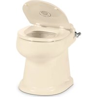
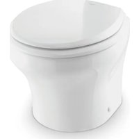
| Product type | Ceramic gravity flush toilet for indoor use in boat or recreational vehicle |
| Brand | Dometic |
| Model | 4410 |
| Series | 4400 |
| Power supply | 12 V DC (direct current) |
| Flush control | Flush switch (touch panel or handle depending on version) |
| Emergency override function | Yes, for manual opening of the flush ball in case of power failure |
| Usage | Boat or recreational vehicle (RV) interior |
| Maintenance | Clean with non-abrasive products; monthly inspection of fittings, wiring, and filters |
| Safety | Disconnect power before maintenance; close water valves for marine applications |
| Recommended spare parts | Flush ball seal, flush ball, electric water valve, vacuum breaker |
| Warranty | Limited warranty, see www.dometic.com/warranty |
| Customer support | Dometic Sanitation Customer Support, phone 1-800-321-9886 |
Frequently Asked Questions - 4410 DOMETIC
User questions about 4410 DOMETIC
0 question about this device. Answer the ones you know or ask your own.
Ask a new question about this device
Download the instructions for your Toilet in PDF format for free! Find your manual 4410 - DOMETIC and take your electronic device back in hand. On this page are published all the documents necessary for the use of your device. 4410 by DOMETIC.
USER MANUAL 4410 DOMETIC
natural_image
Line drawing of a standard toilet with lid and side panel (no text or symbols)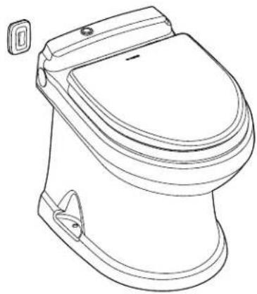
natural_image
Line drawing of a standard two-tone toilet with lid and side door (no text or symbols)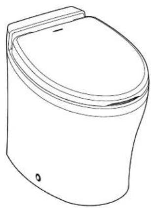
natural_image
Line drawing of a standard open toilet (no text or symbols)4300/4400/6500
EN Full Ceramic Gravity Discharge Toilet
Operation Manual....2
Read these instructions carefully.
These instructions MUST stay with this product.
Contents
1 Explanation of Symbols and Safety Instructions .... 3
1.1 Recognize Safety Information .... 3
1.2 Understand Signal Words....3
1.3 Supplemental Directives....3
1.4 General Safety Messages .... 3
2 Intended Use....4
3 General Information....4
3.1 Recommended Spare Parts .... 4
3.2 Wiring Diagram 4
4 Operation....5
4.1 Using the Flush Touch Panel or Flush Switch .5
4.2 Using the Flush Handle....5
4.3 Using the Bidet Option .... 5
4.4 Understanding the Indicator Lights ..... 6
4.5 Changing the Flush Modes ..... 6
4.6 Initializing the Toilet System ..... 6
4.7 Using the Manual Override Function .....6
4.8 Using the Service Mode Function .....7
5 Maintenance .... 7
5.1 Cleaning the Toilet 7
5.2 Setting an Inspection Schedule ..... 7
5.3 Preparing the Toilet for an Extended Period of Non-Use....7
5.4 Winterizing the Toilet 8
6 Troubleshooting 8
6.1 Troubleshooting Guide....9
7 Service Procedures....11
7.1 Aligning the Cam Switch/Flush Ball.....11
7.2 Removing the Toilet from the Floor ..... 12
7.3 Replacing the Flush Ball Seal ..... 12
7.4 Replacing the Flush Ball .....12
7.5 Replacing the Rotor Shaft 13
7.6 Replacing the Rotor Shaft Cam....13
7.7 Replacing the Motor Drive Arm ..... 13
7.8 Replacing the Drive Linkage ..... 13
8 Disposal 14
LIMITED WARRANTY 14
Customer Support....28
1 Explanation of Symbols and Safety Instructions
This manual has safety information and instructions to help you eliminate or reduce the risk of accidents and injuries.
1.1 Recognize Safety Information

This is the safety alert symbol. It is used to alert you to potential physical injury hazards. Obey all safety messages that follow this symbol to avoid possible injury or death.
1.2 Understand Signal Words
A signal word will identify safety messages and property damage messages, and will indicate the degree or level of hazard seriousness.

DANGER!
Indicates a hazardous situation that, if not avoided, will result in death or serious injury.

WARNING
Indicates a hazardous situation that, if not avoided, could result in death or serious injury.

CAUTION
Indicates a hazardous situation that, if not avoided, could result in minor or moderate injury.
NOTICE: Used to address practices not related to physical injury.
Indicates additional information that is not related to physical injury.
1.3 Supplemental Directives
To reduce the risk of accidents and injuries, please observe the following directives before proceeding to operate or service this appliance:
- Read and follow all safety information and instructions to avoid possible injury or death.
- Read and understand these instructions before operation or servicing of this product.
- Any parts installed during servicing must comply with all applicable local or national codes, including the latest edition of the following standards:
U.S.A.
- ANSI/NFPA70, National Electrical Code (NEC)
- ANSI/NFPA 1192, Recreational Vehicles Code
- ABYC guidelines for marine installations
Canada
- CSA C22.1, Parts I & II, Canadian Electrical Code
– CSA Z240 RV Series, Recreational Vehicles
1.4 General Safety Messages

WARNING: ELECTRICAL SHOCK, FIRE, FLOOD, AND/OR EXPLOSION HAZARD. Failure to obey the following warnings could result in death or serious injury:
- Use only Dometic replacement parts and components that are specifically approved for use with the appliance.
- This product must be installed and serviced by a qualified service technician.
- Do not modify this product in any way. Modifi cation can be extremely hazardous.
- Before beginning maintenance or service on this product, be sure that all electrical power to the unit has been turned off, and for marine applications, ensure that seacocks are in the closed or off position.
- For toilets in marine applications connected to any through-the-hull fittings: always close seacocks when the toilet is not in use (even if the boat is unattended for a brief period).
- For marine applications, instruct all passengers on how to safely close the valves when the toilet is not in use.
- For toilets using fresh water for flushing, disconnect any shoreside or municipal water connections when the boat or RV is unattended for any length of time.
NOTICE: RISK OF PROPERTY DAMAGE. Failure to follow the following notices may cause damage to the toilet or toilet system:
- Only flush water, bodily wastes, and rapid-dissolving toilet tissue.
- Do not overfill the holding tank, or serious damage can occur to the sanitation system. Overfilling the holding tank can rupture the holding tank or release tank contents into the bilge or into the RV.
2 Intended Use
The 4300, 4400, and 6500 series toilets are designed and intended for use only inside a boat or recreational vehicle (hereinafter referred to as "RV") for which it is supplied.
Use these instructions to ensure correct operation of the toilet. Dometic Corporation accepts no liability for damage in the following cases:
- Faulty assembly or connection
- Damage to the product resulting from mechanical influences and excess voltage
• Alterations to the product without expressed permission from Dometic Corporation - Use for purposes other than those described in the operating manual
Dometic Corporation reserves the right to modify appearances and specifications without notice.
3 General Information
This section provides reference information on the components, wiring, and recommended spare parts to keep in stock for the toilet.
The images used in this document are for reference purposes only. Components and component locations may vary according to specific product models. Measurements may vary ±0.38 in. (10 mm).
3.1 Recommended Spare Parts
When operating a boat or other vehicle in remote areas, keep the following spare parts on hand to assure continuous toilet system operation.
Name Part Number
| Flush ball seal |
| Flush ball |
| Electric water valve |
| Vacuum breaker assembly |
See separately packaged parts list for part number.
To order spare parts, refer to "Customer Support" on page 28 for contact information.
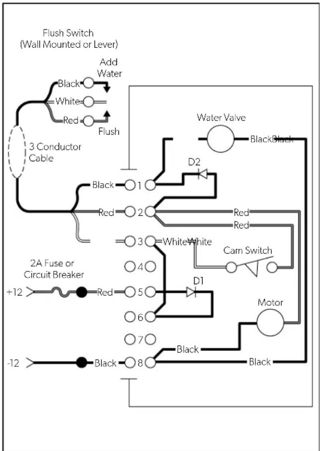
3.2 Wiring Diagram
Figure 1 provides an example of the 4300 and 4400 series toilets wiring specifications.
For the 6500 toilet series, refer to the separately packaged parts list for wiring information.
flowchart
graph TD
    A["3 Conductor Cable"] --> B["Add Water"]
    B --> C["Black"]
    B --> D["White"]
    B --> E["Red"]
    B --> F["Flush"]
    F --> G["2A Fuse or Circuit Breaker"]
    G --> H["+12"]
    G --> I["Red"]
    G --> J["5"]
    G --> K["6"]
    G --> L["7"]
    G --> M["-12"]
    G --> N["Black"]
    G --> O["8"]
    G --> P["D1"]
    G --> Q["D2"]
    G --> R["Water Valve"]
    G --> S["Black"]
    G --> T["Red"]
    G --> U["Cam Switch"]
    G --> V["Motor"]
    G --> W["Black"]
1 4300 and 4400 Series Wiring Diagram
4 Operation
This section has information to help you properly use the basic features associated with the toilet.
4.1 Using the Flush Touch Panel or Flush Switch
This section describes how to properly fill the bowl with water or flush the contents of the bowl, depending on the type of control you have for the toilet.
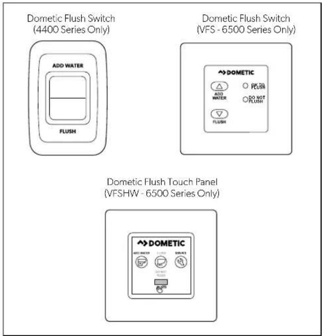
2 Flush Touch Panel and Flush Switch Operation
-
Press and hold the Add Water indicator to fill the bowl. Release the indicator once the desired water level is reached.
-
Press and release the Flush indicator to flush the toilet.
4.2 Using the Flush Handle
4300 Series Only
This section describes how to properly fill the bowl with water or flush the contents of the bowl, using a flush handle.
natural_image
Line drawing of a toilet with a hand valve mechanism inside, showing the lever shift (no text or symbols present)3 4300 Series Flush Handle Operation
- Lift the flush handle to fill the bowl to the desired water level.
- Press the flush handle down, then release it to flush the toilet.
4.3 Using the Bidet Option
6500 Series Only
WARNING: FLOOD HAZARD.
Shut the bidet faucet off completely after use. Failure to obey this warning could result in death or serious injury.
This section describes the proper operation of the bidet function of the toilet.
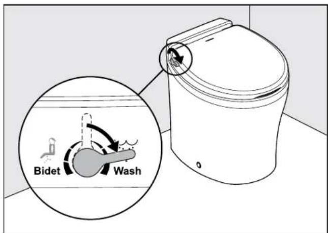
4 6500 Series Wash Function
- Turn the handle toward the front of the toilet to activate the Wash function.
EN
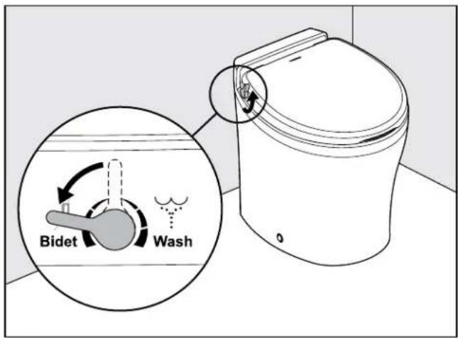
5 6500 Series Bidet Function
- Turn the handle toward the back of the toilet to activate the Bidet function.
4.4 Understanding the Indicator Lights
6500 Series Only
This section explains the indicator lights for the 6500 series toilet control.
Indicator Light Status
| Power on Steady green Electrical power to the toilet is activated | |
| Flashing green Flush mode is changing | |
| Tank level Amber Holding tank is 75% full | |
| Red Holding tank is 100% full | 1 |
The flush actuation is disabled to prevent overfilling the holding tank.
4.5 Changing the Flush Modes
6500 Series Only
This section explains the flush modes available for the 6500 series toilets.
| Flush mode | Action | Volume per flush |
| Normal | Adds water to the bowl after every flush | 1 qt(0.95 L) |
| Dry bowl | Does not add water to the bowl after every flush | 1 pt(0.5 L) |
-
To change modes, press the Flush switch or hold the handle until the power-on light begins flashing (about five seconds).
-
Release the Flush switch or handle.
4.6 Initializing the Toilet System
Before the first use of the toilet system, or before each use after an extended period of non-use, perform the following procedure to get the toilet system ready for operation:
-
Turn on the water supply and electrical power to the toilet.
-
Flush the toilet once to confirm that the toilet functions as expected.
-
Add holding tank deodorant or treatment into the bowl and flush the toilet several times to add additional water into the holding tank (follow the deodorant manufacturer's directions).
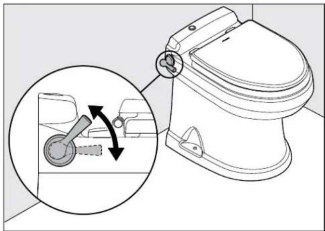
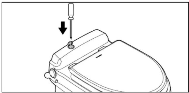
4.7 Using the Manual Override Function
4300 and 4400 Series Only
CAUTION: FLOOD HAZARD.
Shut off the toilet system before performing any service or maintenance tasks and do not leave the vehicle for extended periods of time with the toilet system circuit breaker on. Failure to obey this caution could result in minor or moderate injury.
In the event of a power failure and emergency flushing is required, to clean the toilet bowl or seals, or to perform service or maintenance tasks that require keeping the flush ball open without running water, use the manual override feature.
-
Turn off the main power switch to the toilet.
-
Open the small, round, plastic cover on the back ledge of the toilet.
- Insert a screwdriver or other thin blunt-end rod, and push down on the manual override lever. This opens the flush ball.
natural_image
Line drawing of a toilet with a screwdriver inserted, showing the handle and seat (no text or symbols)6 Manual Override Access
- Perform the desired function.
- Turn on the main power switch to the toilet.
The flush ball closes only after power is restored to the toilet system.
4.8 Using the Service Mode Function
6500 Series Only
To clean the toilet bowl or seals, or to perform service or maintenance tasks that require keeping the flush ball open without running water, use the service switch.
- Push and hold the service switch, located on the control panel, for three seconds.
- Perform the required tasks.
- After the tasks are complete, push and hold the service switch for three seconds to change the toilet mode back to normal operation.
5 Maintenance
NOTICE: Do not use abrasive cleaners, caustic chemicals, or lubricants and cleaners that contain alcohols or petroleum distillates. Failure to obey this notice may cause damage to the toilet's internal seals.
This section provides maintenance procedures recommended to keep the toilet operating correctly.
EN
5.1 Cleaning the Toilet
Use non-abrasive cleaners to maintain the original appearance of the toilet.
Follow this procedure to clean the toilet:
- Add cleanser to the toilet bowl.
- Clean the bowl by following the manufacturer's instructions on the label of the cleanser.
- Flush the toilet in normal mode to clear the bowl of cleanser and debris.
- Wipe down the toilet body using a damp cloth.
5.2 Setting an Inspection Schedule
Set up a monthly and yearly inspection schedule to ensure the toilet system is functioning properly. The following table holds suggested inspection items to include on your schedule.
Schedule Inspection Task
| Monthly Inspect the toilet, plumbing, plumbing connections, wiring, and wiring connections. |
| Open and close all of the plumbing valves, including the seacocks (for marine applications). |
| Check the inline water filters and the vented loops for blockages. |
Yearly Check the water valve inlet filter.
5.3 Preparing the Toilet for an Extended Period of Non-Use
Follow this procedure when not using the boat or RV for an extended period of time:
- Flush the toilet in normal mode.
- Add 4 oz (120 ml) of liquid biodegradable laundry detergent. The laundry detergent should not contain bleach or other environmentally harmful substances.
If sea water is used for flushing:
– Turn off the power to the sea water pump.
- Pour fresh water directly into the bowl during the flush cycle.
- Flush the toilet five times to clear the bowl.
- Turn off the water supply to the toilet.
- Flush the toilet without water four times to clear the remaining water from the system.
- Turn off the power to the toilet.
- Completely pump out the holding tank.
- If the system will be subjected to freezing temperatures, follow the above procedure, then proceed to "5.4 Winterizing the Toilet" on page 8.
5.4 Winterizing the Toilet
WARNING: HEALTH HAZARD.
Do not use an automotive-type antifreeze in fresh-water systems. Failure to obey this warning could result in death or serious injury.
Before an extended period of non-use in a climate where temperatures will fall below freezing, the toilet system should be winterized for storage. Use the following procedure for winterization of the system:
- Thoroughly flush the system with fresh water.
- Drain the potable tank.
- Empty the holding tank.
- Add potable-water antifreeze to the fresh-water tank.
The amount of antifreeze needed may vary, depending on the installation.
- Flush the potable-water antifreeze and water mixture through the toilet and into the entire plumbing system. Each installation is different, so amounts may vary. User discretion is required to assure adequate protection.
- Turn off the power to the toilet.
- Empty the holding tank of any remaining contents.
6 Troubleshooting
This section has information to help you identify and remedy various functional issues associated with your toilet. Refer to "7 Service Procedures" on page 11 for additional information. Any service procedures referenced are intended for emergency purposes.
For additional details on an operational issue, potential cause, or remedy, contact Customer Service. Refer to "Customer Support" on page 28.
6.1 Troubleshooting Guide
| Operational Issue Possible Cause Remedy | ||
| The toilet will not flush and water will not enter the toilet bowl. | The fuse is blown or the circuit breaker is tripped. | ·Check the toilet fuse or circuit breaker at the DC distribution panel.·Check for loose/defective wiring between the power source and the toilet (terminal block pins 5 and 8, for 4300 and 4400 series).·Check for reverse polarity of the incoming power.·For 4300 and 4400 series: check for a defective diode D1 at pin 5 of the terminal block. |
| The toilet will not flush, but water enters the toilet bowl. | There is an electrical or mechanical failure related to the flush valve. | ·Check for loose/defective wiring between the flush switch and the toilet (terminal block pins 2 and 3, for 4300 and 4400 series).·Check for a defective flush switch. Replace if necessary.·Check for loose flush ball motor wires (terminal block pins 2 and 8, for 4300 and 4400 series).·Check for a defective flush ball motor. Replace if necessary.·Check for a motor drive arm failure. Replace if necessary. Refer to section "7.7 Replacing the Motor Drive Arm" on page 13.·Check for a drive linkage failure. Replace if necessary. Refer to section "7.8 Replacing the Drive Linkage" on page 13. |
| The toilet flushes, but water does not enter the toilet bowl. | The water supply is blocked or there is an electrical failure. | ·Check for a blockage in the water line to the toilet. Remove the line and clear the blockage.·Check for a clog in the filter screen at the water valve inlet. Remove the water line and clear the debris.·Check for loose or defective wiring between the water valve and toilet (terminal block pins 1 and 8, for 4300 and 4400 series).·Check for a defective water valve. Replace if necessary. |
| Water does not enter the toilet bowl when the flush handle or the wall switch is in the "Add Water" position. | There is an electrical connection failure. | ·Check for loose or defective wiring between the flush switch and toilet (terminal block pins 1 and 3, for 4300 and 4400 series).·Check for a defective flush switch. Replace if necessary. |
| The water will not shut off and causes the toilet bowl to overflow. | There is a water valve failure. | ·Check for debris in the water valve.·Check for a defective water valve. Replace if necessary. |
| The flush ball constantly cycles between the open and closed position. | There is a component adjustment required or a component is defective. | ·Check the cam switch for adjustment. Refer to section "7.1 Aligning the Cam Switch/Flush Ball" on page 11.·Check for a defective cam switch. Replace if necessary.·Check for defective drive linkage. Replace if necessary. Refer to section "7.8 Replacing the Drive Linkage" on page 13.·Check for shorted wiring between the flush switch and toilet (terminal block pins 2 and 3, for 4300 and 4400 series).·Check for a defective flush switch. Replace if necessary. |
| The flush ball opens slowly or will not open when the manual flush lever is pressed. | A component adjustment is required or there is a defective component. | ·Check for a defective flush spring assembly. Replace if necessary.·Check for excessive drag between the flush ball and the flush ball seal. Lubricate the flush ball and seal it with silicone spray. |
| The flush switch must be held in the "Flush" position to close the flush ball. | There is a defective electrical component. | ·Check for loose or defective wiring (for 4300 and 4400 series, check between the cam switch and terminal block pins 2, 3, and 6).·Check for a defective cam switch. |
| The flush ball does not close completely. | A component adjustment is required or there is a defective component. | ·Check the cam switch for adjustment. Refer to section "7.1 Aligning the Cam Switch/Flush Ball" on page 11.·Check for a defective cam switch. Replace if necessary.·Check that the rotor shaft cam is not loose or defective. If defective, replace the rotor shaft cam. Refer to section "7.6 Replacing the Rotor Shaft Cam" on page 13.·Check for worn drive linkage. Replace if necessary. Refer to section "7.8 Replacing the Drive Linkage" on page 13. |
| A squeaky noise occurs when the flush ball is opening. | Lubrication of the component(s) is required. | ·Check the drive arm/drive linkage joint. Apply lubrication using silicone grease, if necessary.·Check if the flush ball and seal needs lubrication. Use silicone spray if necessary. |
| Water will not stay in the bowl and leaks down through the flush ball seal. | There is an incomplete seal between the flush ball and the rubber seal. | ·Check the cam switch for adjustment. Refer to section "7.1 Aligning the Cam Switch/Flush Ball" on page 11.·Check if the mounting bolts that hold the base assembly to the ceramic toilet needs tightening. Tighten to 20-25 in-lb (2.3-2.8 Nm) of torque. Notice: Excessive tightening of the bolts can damage the toilet.·Check to see if the flush ball seal is worn and needs replacement. Refer to section "7.3 Replacing the Flush Ball Seal" on page 12.·Check for a defective flush ball. Replace if necessary. Refer to section "7.4 Replacing the Flush Ball" on page 12. |
| The toilet flushes in both the "Add Water" and the "Flush" switch positions. | There is a defective electrical component. | ·For 4300 and 4400 series: check for a defective diode D2 on terminal block pins 1 and 2. Replace if necessary. |
| Water will not enter the toilet bowl during the "Flush" cycle. | There is a defective electrical component or the water may be turned off. | ·For 4300 and 4400 series: check for a defective diode D2 on terminal block pins 1 and 2. Replace if necessary.·Confirm the water is turned on and the water valve is open. Turn the water on, and open the water valve, if applicable. |
| Water is leaking from the toilet onto the floor. | There is a loose connection or a defective component. | ·Check for a loose water line connection. Tighten the connection, if necessary.·Check for a loose or defective vacuum breaker. Replace if necessary.·Check for a defective water valve. Replace if necessary.·Check for a defective ball seal.·Check if the mounting bolts that hold the base assembly to the ceramic toilet needs tightening. Tighten to 20-25 in-lb (2.3-2.8 Nm) of torque. Notice: Excessive tightening of the bolts can damage the toilet. |
7 Service Procedures

WARNING: ELECTRICAL SHOCK, FIRE, FLOOD, AND/OR EXPLOSION HAZARD. Failure to obey the following warnings could result in death or serious injury:
- Use only Dometic replacement parts and components that are specifically approved for use with the appliance.
- This product must be installed and serviced by a qualified service technician.
- Do not modify this product in any way. Modifi cation can be extremely hazardous.
• Always disconnect the unit from power before servicing. Confirm that all electrical power to the unit has been turned off, and for marine applications, ensure that seacocks are in the closed or off position.
This section has information to help you service the unit components, if needed. These service procedures are intended for emergency purposes. Contact "Customer Support" on page 28.
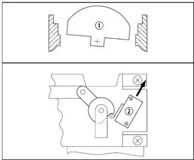
7.1 Aligning the Cam Switch/Flush Ball
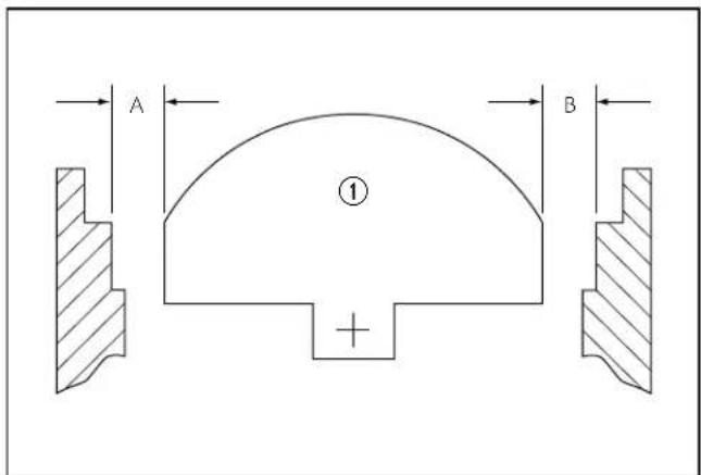
7 Correct Cam Switch/Flush Ball Alignment
① Flush Ball
The flush ball should be properly positioned so that the "A" and "B" distances are equal (see Figure 7).
If the flush ball becomes misaligned, water can leak from the bowl or other flushing problems will occur.
To resolve these problems, perform the following actions as applicable to the over-travel or under-travel condition of the cam switch/flush ball alignment.
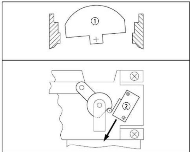
8 Over-Travel Condition and Fix
9 Under-Travel Condition and Fix
① Flush Ball
② Cam Switch
- Turn off water and electrical power to the toilet.
- Disconnect the water line.
- Remove the toilet from the floor. Refer to section "7.2 Removing the Toilet from the Floor" on page 12.
- Loosen the cam switch mounting screws using a 3/32 in. (0.25 mm) hex tool and a 1/4 in. (6 mm) box-end wrench.
EN
- Slide the cam switch up or down depending on the flush ball position:
- Over-travel: The flush ball leans to the back of the toilet. Slide the cam switch down.
- Under-travel: The flush ball leans to the front of the toilet. Slide the cam switch up.
- Tighten the cam switch mounting screws.
- Apply electrical power and check the adjustment.
- Repeat steps 4–7 as necessary.
- After the cam switch and flush ball are properly positioned, reinstall the toilet.
7.2 Removing the Toilet from the Floor
Follow this procedure to remove the toilet when needed for servicing:
- Turn off the water and the electrical power to the toilet.
- Remove the water inlet hose from the toilet.
- Remove the toilet from the floor and turn it upside-down.
Make sure the power wires are secure.
7.3 Replacing the Flush Ball Seal
Follow this procedure to replace the flush ball seal:
- Perform the steps in "7.2 Removing the Toilet from the Floor" on page 12.
- Disconnect the service switch wires at the in-line connectors.
- Remove the three nuts and flat washers securing the base assembly to the toilet bowl, using a 1/4 in. (6 mm) drive ratchet wrench, 7/16 in. (13 mm) deep-well socket, and an extension.
- Pull the check valve out of the sealing grommet located in the rear of the toilet bowl.
- Lift the base assembly from the toilet.
-
Replace the old seals with a new complete seal kit.
-
Reconnect the base assembly to the toilet with the new mounting bolts (L-shaped) included with the seal kit. Tighten the nuts to 20–25 in-lb (2.3–2.8 Nm) torque.
- Reconnect the service switch wires.
- Reattach the water inlet hose to the toilet.
- Reinstall the toilet to the floor.
7.4 Replacing the Flush Ball
Follow this procedure to replace the flush ball:
- Turn off the water to the toilet.
- Open the flush ball in service mode or using manual override, depending on the toilet series. Refer to section "4.8 Using the Service Mode Function" on page 7 or section "4.7 Using the Manual Override Function" on page 6.
- Turn off electrical power to the toilet.
- Disconnect the water inlet hose.
- Remove the toilet from the floor and turn it upside-down.
- Disconnect the service switch wires at in-line connectors.
- Pull the check valve out of the sealing grommet located in the rear of the toilet bowl.
- Remove the three nuts and flat washers securing the base assembly to the ceramic toilet bowl, using a 1/4 in. (6 mm) drive ratchet wrench, 7/16 in. (13 mm) deep-well socket, and an extension.
- Lift the base assembly from the toilet.
- Remove the bowl seal, the flush-ball seal, and the retainer plate to expose the flush ball.
- Loosen the set screw in the rotor shaft cam, using a 1/8 in. (4 mm) hex tool.
- Remove the #8 x 1/4 in. (6 mm) screw and flat washer from the linkage slot.
-
Remove the four screws securing the mounting bracket to the base.
-
Pull the mounting bracket and the rotor cam off the base.
- Rotate the flush ball forward and remove the flush-ball retaining screw.
- Replace the flush ball.
- Reverse the disassembly procedure. Before reassembling the entire toilet:
- Push the rotor cam all the way onto the rotor shaft and tighten the set screw.
– Lubricate the moving parts with silicone grease.
- Check the cam switch for adjustment. See "7.1 Aligning the Cam Switch/Flush Ball" on page 11.
7.5 Replacing the Rotor Shaft
Follow this procedure to replace the rotor shaft:
- Follow the disassembly steps in "7.4 Replacing the Flush Ball" on page 12.
- Pull the rotor shaft out from inside the base.
- Lubricate the O-rings on the new shaft using silicone grease.
- Align the flat section on the rotor shaft with the flat section in the cam.
- Push the rotor shaft cam fully onto the rotor-shaft. Tighten the set screw.
- Lubricate all moving parts using silicone grease.
- Reverse the disassembly procedure. Before attaching the base to the toilet, check the cam switch for adjustment. See "7.1 Aligning the Cam Switch/Flush Ball" on page 11.
7.6 Replacing the Rotor Shaft Cam
Follow this procedure to replace the rotor shaft cam:
- Follow disassembly steps under "7.4 Replacing the Flush Ball" on page 12.
- Remove the linkage pin clip and pin.
- Attach the new rotor shaft cam to the linkage, using the pin and clip.
EN
- Lubricate all moving parts using silicone grease.
- Reverse the disassembly procedure.
- Reverse the disassembly procedure. Before attaching the base to the toilet, check the cam switch for adjustment. See "7.1 Aligning the Cam Switch/Flush Ball" on page 11.
7.7 Replacing the Motor Drive Arm
Follow this procedure to replace the motor drive arm:
- Follow the disassembly steps in "7.4 Replacing the Flush Ball" on page 12.
- Remove the four motor-mounting screws.
- Remove the motor from the mounting bracket.
- Loosen the drive-arm set screw using a 3/32 in. (0.25 mm) hex tool.
- Remove the old drive-arm.
- Install the new drive arm and push it on the motor shaft as far as possible.
- Tighten the set screw.
- Lubricate all moving parts using silicone grease.
- Reverse the disassembly procedure. Before attaching the base to the toilet, check the cam switch for adjustment. See "7.1 Aligning the Cam Switch/Flush Ball" on page 11.
7.8 Replacing the Drive Linkage
Follow this procedure to replace the drive linkage:
- Follow the disassembly steps in "7.4 Replacing the Flush Ball" on page 12.
- Remove the linkage pin clip and pin at the rotor shaft cam.
- Remove the flush spring retaining screw and washer from the retaining post.
- Remove the flush spring from the old linkage.
- Insert the flush spring to the new linkage
-
Reattach the spring to the retaining post.
-
Attach the linkage to the rotor shaft cam using the pin and clip.
- Lubricate all moving parts using silicone grease.
- Reverse the disassembly procedure.
8 Disposal
Place the packaging material in the appropriate recycling waste bins, whenever possible. Consult a local recycling center or specialist dealer for details about how to dispose of the product in accordance with all applicable national and local regulations.
LIMITED WARRANTY
LIMITED WARRANTY AVAILABLE AT WWW.DOMETIC.COM/WARRANTY.
IF YOU HAVE QUESTIONS, OR TO OBTAIN A COPY OF THE LIMITED WARRANTY FREE OF CHARGE, CONTACT:
DOMETIC CORPORATION SANITATION CUSTOMER SUPPORT CENTER 13128 STATE ROUTE 226 BIG PRAIRIE, OHIO, USA 44611 1-800-321-9886
Lire attentivement ces instructions. Ces instructions
Customer Support.....28
natural_image
Line drawing of a toilet with a hand valve mechanism inside, showing the lever mechanism and its rotation (no text or symbols)natural_image
Line drawing of a toilet with a screwdriver inserted, showing the handle and seat (no text or symbols)For the Authorized Service Center near you, call between 8:00 a.m. and 5:00 p.m., Monday through Friday, or contact the nearest Parts Distributor. Hours may vary.
DOMETIC
www.dometic.com
Dometic Sanitation Division
Customer Support Center
13128 St. Rte. 226
Big Prairie, OH 44611
+1 800-321-9886 (USA and Canada)
+330-439-5550(International)
+330-496-3097(USA and Canada)
+330-439-5567(International)
AUSTRALIA
Dometic Australia Pty. Ltd.
1 John Duncan Court
Varsity Lakes QLD 4227
1800212121
昌+61755076001
Mail: sales@dometic.com.au
AUSTRIA
Dometic Austria GmbH
Neudorferstraße 108
A-2353 Guntramsdorf
+43 2236 908070
吕+43223690807060
Mail: info@dometic.at
BENELUX
Dometic Branch Office Belgium
Zincstraat 3
B-1500 Halle
+32 2 3598040
吕+32 2 3598050
Mail: info@dometic.be
BRAZIL
Dometic DO Brasil LTDA
Avenida Paulista 1754, conj. 111
SP 01310-920 Sao Paulo
+551132513352
马+551132513362
Dometic Group Asia Pacific
Suites 2207-11 · 22/F · Tower 1
The Gateway · 25 Canton Road,
Tsim Sha Tsui · Kowloon
+85224611386
+852 2 4665553
Mail: info@waeco.com.hk
HUNGARY
Dometic Zrt. Sales Office
Kerékgyártó u. 5
H-1147 Budapest
+3614684400
+3614684401
Domettic Italy S.r.l.
Via Virgilio, 3
I-47122 Forlì (FC)
+39 0543 754901
品+390543754983
Mail: vendite@dometic.it
JAPAN
Dometic KK
Maekawa-Shibaura, Bldg. 2
2-13-9 Shibaura Minato-ku
Tokyo 108-0023
+81 3 5445 3333
+81354453339
Mail: info@dometic.jp
MEXICO
Circuito Médicos No. 6 Local
Colonia Ciudad Satélite
CP 53100 Naucalpan de Juárez
Estado de México
+52 55 5374 4108
+52 55 5393 4683
Mail: info@dometic.com.mx
NETHERLANDS
Dometic Benelux B.V.
Ecustraat 3
NL-4879 NP Etten-Leur
+31 76 5029000
日+31765029019
Mail: info@dometic.nl
NEW ZEALAND
Dometic New Zealand Ltd.
PO Box 12011
Penrose
Auckland 1642
16496221490
+6496221573
Mail: customerservices@dometic.co.nz
NORWAY
Dometic Norway AS
∅sterøyveien 46
N-3232 Sandefjord
宮+4733428450
14733428459
Mail: firmapost@dometic.no
POLAND
Dometic Poland Sp. z o.o.
Ul. Puławska 435A
PL-02-801 Warszawa
+48 22 414 3200
+48 22 414 3201
Mail: info@dometic.pl
PORTUGAL
Dometic Spain, S.L.
Komsomolskaya square 6-1
RU-107140 Moscow
+7 495 780 79 39
+7 495 916 56 53
Mail: info@dometic.ru
SINGAPORE
Dometic Pte Ltd
18 Boon Lay Way 06-140 Trade Hub 21
Singapore 609966
+65 6795 3177
+65 6862 6620
Mail: dometic@dometic.com.sg
SLOVAKIA
Dometic Slovakia s.r.o. Sales Office
Bratislava
Nádražná 34/A
900 28 Ivánka pri Dunaji
円/目 +421245529680
Mail: bratislava@dometic.com
SOUTH AFRICA
Dometic (Pty) Ltd.
Regional Office
South Africa & Sub-Saharan Africa
2 Avalon Road
West Lake View Ext 1
Modderfontein 1645
Johannesburg
+27114504978
+27114504976
Mail: info@dometic.co.za
SPAIN
Dometic Spain S.L.
Avda. Sierra del Guadarrama, 16
E-28691 Villanueva de la Cañada
Madrid
134918336089
+34 900 100 245
Mail: info@dometic.es
SWEDEN
Dometic Scandinavia AB
Gustaf Melins gata 7
Dometic Switzerland AG
Riedackerstrasse 7a
CH-8153 Rümlang
+41 44 8187171
+41 44 8187191
Mail: info@dometic.ch
UNITED ARAB EMIRATES
Dometic Middle East FZCO
P.O.Box17860
S-D 6, Jebel Ali Freezone
Dubai
+97148833858
+97148833868
Mail: info@dometic.ae
UNITED KINGDOM
Dometic UK Ltd.
Dometic House, The Brewery
Blandford St. Mary
Dorset DT11 9LS
+44 344 626 0133
E +44 344 626 0143
Mail: customerservices@dometic.co.uk
USA & CANADA
Dometic Marine Division
2000 North Andrews Avenue
Pompano Beach, FL 33069
+1800-542-2477
E+1954-979-4414
Mail: marinesales@dometic.com
Dometic RV Division
1120 North Main Street
Elkhart, IN 46515
+1 574-264-2131
Dometic Sanitation Division
13128 St. Rte. 226
Big Prairie, OH 44611
需+1800-321-9886
+330-496-3097