EY7202 - Screwdriver PANASONIC - Free user manual and instructions
Find the device manual for free EY7202 PANASONIC in PDF.
| Product type | Cordless impact driver |
| Brand | Panasonic |
| Model | EY7202 |
| Dimensions (L) | 167 mm (6-9/16") |
| Weight (with battery) | 1.85 kg |
| Power supply | Rechargeable battery 12 V DC (Ni-MH or Ni-Cd) |
| Included battery | EY9201 (3.5 Ah Ni-MH) |
| Charger | EY0110 with charging time 55 min for EY9201 |
| Motor | DC motor 12 V |
| No load speed | Soft mode: 0-2000 rpm; Medium mode: 0-2450 rpm; Hard mode: 0-2600 rpm |
| Maximum torque | 120 Nm |
| Impacts per minute | Soft mode: 0-2000; Medium mode: 0-2500; Hard mode: 0-2800 |
| Chuck | Quick hex 6.35 mm (1/4") |
| Main functions | Digital clutch (16 levels + F), single percussion impact function, impact power mode selection (soft/medium/hard), LED light, adjustable belt hook |
| Safety | Reversing lever with center lock, automatic overload shut-off, immediate bit brake |
| Maintenance | Clean with a dry, clean cloth; do not use water, solvent, or volatile cleaner |
| Spare parts and repairability | Batteries and charger available separately; technical support at authorized dealer |
Frequently Asked Questions - EY7202 PANASONIC
User questions about EY7202 PANASONIC
0 question about this device. Answer the ones you know or ask your own.
Ask a new question about this device
Download the instructions for your Screwdriver in PDF format for free! Find your manual EY7202 - PANASONIC and take your electronic device back in hand. On this page are published all the documents necessary for the use of your device. EY7202 by PANASONIC.
USER MANUAL EY7202 PANASONIC
Operating Instructions
Bedienungsanleitung
Cordless Impact Driver
Before operating this unit, please read these instructions completely and save this manual for future use.
YkpaHcbka: CtopiHa 114
FUNCTIONAL DESCRIPTION
FUNKTIONSBESCHREIBUNG
DESCRIPTION DES FONCTION
DESCRIZIONE DELLE FUNZION
FUNCTIEBESCHRIJVING
DESCRIPCION FUNCIONAL
FUNKTIONSBESKRIVELSE
FUNKTIONSBESKRIVNING
FUNKSJONSBESKRIVELSE
TOIMINTOJEN KUVAUS
ФУHKЦИОHAЛьНОПСАн
ФУHKЦIOHAЛьНОПС
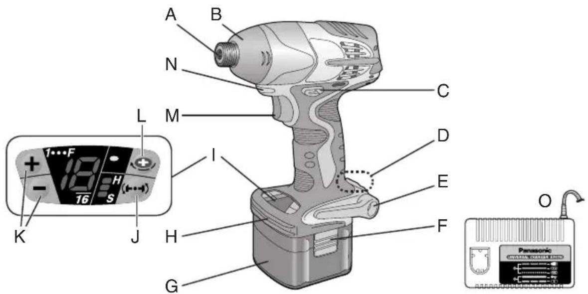
Fig. 1
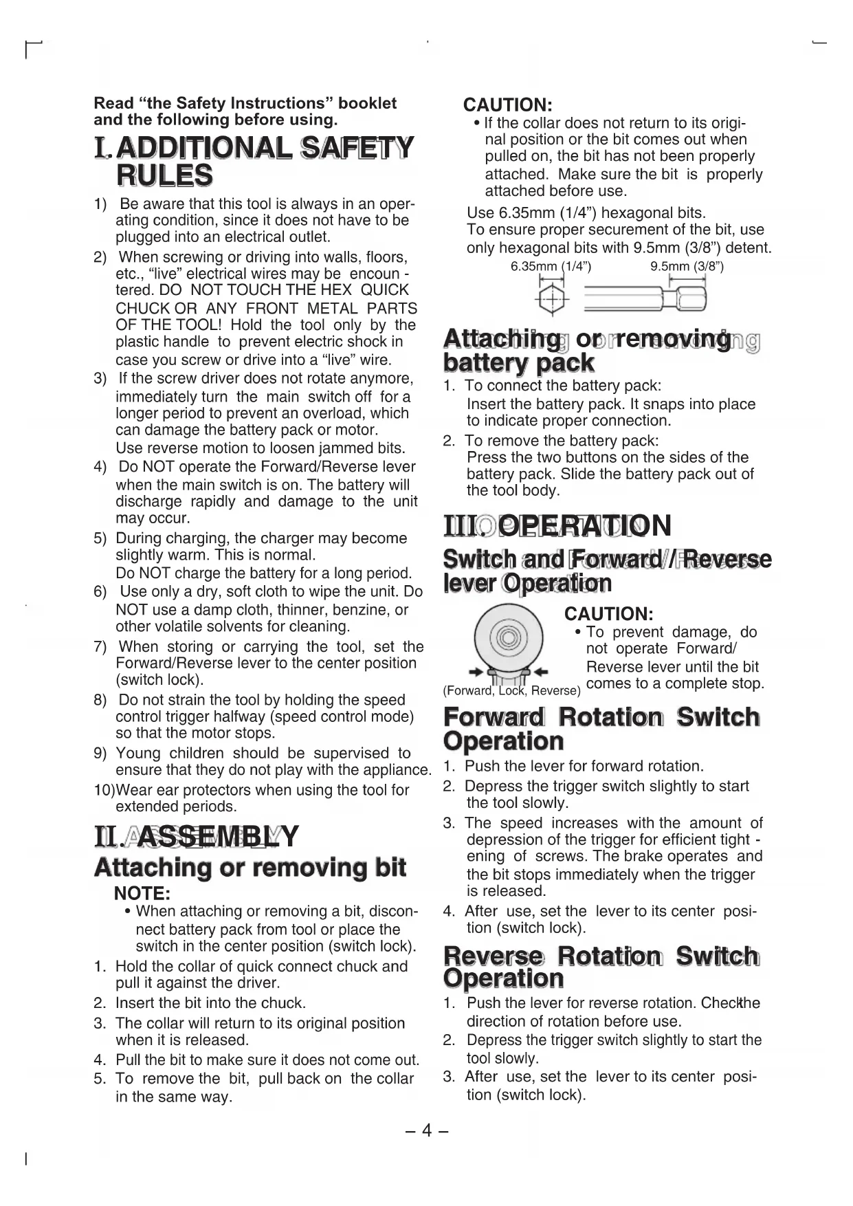
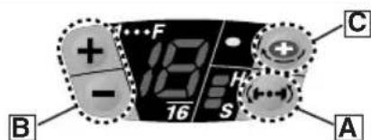
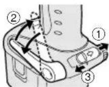
| A | 6.35 mm (1/4") hexrapnuck neck chuck 6.35 mm (1/4") Sechskant-Schnellaufspannffutter Mandrin de connexion rapide hexagonal de 6,35 mm (1/4") Mandrino esagonale di collegamento rapido da 6,35 mm (1/4") 6,35 mm zeskantboorkop met snelkoppeling Mandril hexagonal de conexión rápida de 6,35 mm (1/4") Snabbchuck med 6,35 mm sexkantshylsa 6,35 mm (1/4") hexartgikolingschuck 6,35 mm (1/4") kuusipikaistukka 6,35 MM (1/4") uestirpanhny latpnoh blyctrogo noedocnne 6,35 MM (1/4") uestirpanhny latpno h wibidko prncdahnna | B | Nose protector Frontabdeckung Protection du bec Protezione frontale Neusbesserer Protector del morro Nesebeskyter Nosskydd Nesebeskyter Kärjen suojus Pecnipatop Pecnipatop | C | Forward/Reverse lever Vorwärts/Rückwartshelbe Levier d' inversion marche avant/marche arriere Leva di avanzamento/inversione Links/rechtschakelaar Palanca de avance/marcha atrás Greb til forlaens/baglæns retining Riktningsomkopplare Forover-/bakoverbtryter Eteenpäin/taaksepiin vipu Рычаг поеклочени вперед/назд Вaxьль поемкинь вперед/назд |
| D | Belt hook lock lever Riemenhaken-Verriegelungshebel Levier de verrouillage du crochet de cointure Leva di blocco gancio da cintura Borghendel voor riemclip Palanca de bloqueo del gancho de cinturo Låsehandtag til bæltekrog Låsknapp für båteskrok Läsespak for beltekrok Vyölenkin luktusvipu Бухаг Фкcaцни посно крюka Вaxínbø φíckaüi посно крюka | E | Belt hook Riemenhaken Crochet de cointure Gancio da cintura Riemclip Gancho del cinturón Bæltekrog Bäteskrok Beltekrok Vyölenkki Посhornо крю Посhornо крю | F | Battery pack release button Akku-Entriebungsknopf Bouton de libération de batterie autonome Tasto di rilascio pacco batteria Accu-ontgrendeloets Botón de liberación de batería Udløserknaptil betarpakning Frigöringsknapp für batteri Utløserknapp für batteripakke Akkupaketin irrotuspainike Конда освобождени варейного блажа Конда виевленья варейного等相关 |
| G | Battery pack (EY9201) Akku (EY9201) Batterie autonome (EY9201) Pacco battery (EY9201) Accu (EY9201) Batteria (EY9201) Batteripakning (EY9201) Batteri (EY9201) Batteripakke (EY9201) Akku (EY9201) Батарийкий (EY9201) Батарийкий (EY9201) | H | Bit holder (inside of the body) Einsatzhalter (im Maschinenkorper) Porte-mèche (intérieur du corps) Portabit (all'interno della struttura) Bithouder (geintegreerd in de behuizing) Soporte de broca (en el interior del cuerpo) Bitholder (indvendig i vaerktojet) Bithallare (inuti holjet) Bitholder (inne i maskinhuset) Terän pidin (rungon sisälä) Остес对于我们 xanpenées有很大変 (BHytrpi koprnyca) Bvdsekдд захалень有很大変 (Bcepeini koprnyca) | L | Control panel Bedienfeld Panneau de commande Pannello di controllo Bedieningspaneel Panel de control Kontrolpanel Kontrollpanel Kontrollpanel Saatöpaneeli Панель уразаленя Панelier уразаленя |
| J | Impact power mode button Schlagkraftmodustaste Bouton de mode de puissance d'impact Tasto modalità potenza impatto Slagkracht-functietoets Botón de modo de potencia de impact Slagkraftfunckionsknap Slagkraftsväljare Innstillingsknapp for slagstyrke Iskutehomoodon painike Конда ржима мошосту уда Конда ржиму посту уда | R | Digital clutch button Digitalkupplungs-Einstelllasten Bouton de réglage d'embrage numérique Tasto regolazione frizione digitale Insteltoetsen voor digitaile koppeling Botoon de ajuste de embrace digitale Knap til digital koblingsindstilling Knapper for installingv van digital koppling Innstillingsknapp for digital clutch Digitalainen noyktemen sātöpanike Конда уstačobankи有很大変 (BHytrpi koprnyca) Конда устови有很大変 (Bcepeini koprnyca) | L | One-shot impact button One-Shot-Schlagmodustaste Bouton d'impact à une seule percussion Tasto percussione unica Eén-shot slagfunctietoets Botón de impacto de un disparo Knap til engangsslag Knapforbitvis slagskruvdragning One-shot slagknapp Kertaiskupainike Конда ржима одиноч然是有很大変 Конда ржиму одиноч然是有很大変 |
| M | Variable speed control trigger Elektronikschalter Gächette de commande de vitesse Grilletto di controlo velocità variabile Startschakelaar met variabile torentalregeling Disparader del control de velocidad variable Kontroludloser for variabel hastighed Avtryckare med variabel varvtalsregeling Hovedbryter, trinnlos Noopedensäätokytkin Пerekenhoatele ржимову рeremenenский Пerekenmikanay рereнковань змін hoішvidektо | LED light LED-Leuchtte Lumière DEL Luce LED LED-lampje Luz indicadora LED-lys LED-ljus LED-lys LED-valo С被告оind�ая有很大変 (BHytrpi koprnyca) С被告оind�ая有很大変 (Bcepeini koprnyca) | O | Battery charger (EY0110) Ladegerät (EY0110) Chargeur de batterie (EY0110) Caricabatteria (EY0110) Acculader (EY0110) Cargador de baterias (EY0110) Batterioplader (EY0110) Batteriladdare (EY0110) Batterilader (EY0110) Akkulaturi (EY0110) Зарадноу有很大変 (EY0110) Зарадноу有很大変 (EY0110) |
Read "the Safety Instructions" booklet and the following before using.
I. ADDITIONAL SAFETY RULES
1) Be aware that this tool is always in an operating condition, since it does not have to be plugged into an electrical outlet.
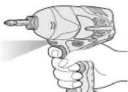
2) When screwing or driving into walls, floors, etc., "live" electrical wires may be encountered. DO NOT TOUCH THE HEX QUICK CHUCK OR ANY FRONT METAL PARTS OF THE TOOL! Hold the tool only by the plastic handle to prevent electric shock in case you screw or drive into a "live" wire.
3) If the screw driver does not rotate anymore, immediately turn the main switch off for a longer period to prevent an overload, which can damage the battery pack or motor. Use reverse motion to loosen jammed bits.
4) Do NOT operate the Forward/Reverse lever when the main switch is on. The battery will discharge rapidly and damage to the unit may occur.
5) During charging, the charger may become slightly warm. This is normal. Do NOT charge the battery for a long period.
6) Use only a dry, soft cloth to wipe the unit. Do NOT use a damp cloth, thinner, benzine, or other volatile solvents for cleaning.
7) When storing or carrying the tool, set the Forward/Reverse lever to the center position (switch lock).
8) Do not strain the tool by holding the speed control trigger halfway (speed control mode) so that the motor stops.
9) Young children should be supervised to ensure that they do not play with the appliance.
10)Wear ear protectors when using the tool for extended periods.
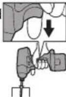
II.ASSEMBLY Attaching or removing bit NOTE:
-
When attaching or removing a bit, disconnect battery pack from tool or place the switch in the center position (switch lock).
-
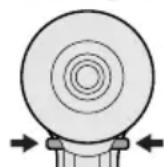
Hold the collar of quick connect chuck and pull it against the driver.
- Insert the bit into the chuck.
- The collar will return to its original position when it is released.
- Pull the bit to make sure it does not come out.
- To remove the bit, pull back on the collar in the same way.
CAUTION:
- If the collar does not return to its original position or the bit comes out when pulled on, the bit has not been properly attached. Make sure the bit is properly attached before use.
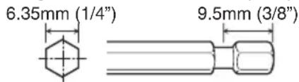
Use 6.35mm (1/4") hexagonal bits.
To ensure proper securement of the bit, use only hexagonal bits with 9.5mm (3 / 8^ ) detent.
Attaching orremoving battery pack
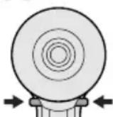
- To connect the battery pack: Insert the battery pack. It snaps into place to indicate proper connection.
- To remove the battery pack: Press the two buttons on the sides of the battery pack. Slide the battery pack out of the tool body.
IIIOPERATION
Switch and Forward/Reverse lever Operation
(Forward, Lock, Reverse)
CAUTION:
To prevent damage, do not operate Forward/ Reverse lever until the bit comes to a complete stop.
Forward Rotation Switch Operation
- Push the lever for forward rotation.
- Depress the trigger switch slightly to start the tool slowly.
- The speed increases with the amount of depression of the trigger for efficient tightening of screws. The brake operates and the bit stops immediately when the trigger is released.
- After use, set the lever to its center position (switch lock).
Reverse Rotation Switch Operation
- Push the lever for reverse rotation. Check the direction of rotation before use.
- Depress the trigger switch slightly to start the tool slowly.
- After use, set the lever to its center position (switch lock).
CAUTION:
- To eliminate excessive temperature increase of the tool surface, do not operate the tool continuously using two or more battery packs. Tool needs cool off time before switching to another pack.
LED light
CAUTION:
- The built-in LED light is designed to illuminate the small work area temporarily.
- Do not use it as a substitute for a regular flashlight, since it does not have enough brightness.
Depress the trigger switch, then LED light turns on. When the trigger switch is released, the light turns off automatically. The light illuminates with
very low current, and it does not adversely affect the performance of the driver during use or its battery capacity.
This product has the built-in LED light. This product is classified into "Class 1 LED Product" to EN 60825-1
Class 1 LED Product
Caution: DO NOT STARE INTO BEAM.
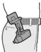
How to use the belt hook
WARNING!
- Be sure to attach the belt hook securely to the main unit with the screw firmly fastened. When the belt hook is not firmly attached to the main unit, the hook may depart and the main unit may fall. This may result in an accident or injury.
Periodically check screw for tightness. If found to be loose, tighten firmly.
-
Be sure to attach the belt hook firmly and securely onto a waist belt or other belt. Pay attention to the unit not slipping off from the belt. This may result in an accident or injury.
-
When the main unit is held by the belt hook, avoid jumping or running with it. Doing so may cause the hook to slip and the main unit may fall.
This may result in an accident or injury.
- When the belt hook is not used, be sure to return it to the storing position. The belt hook may catch on something.
This may result in an accident or injury.
- When the unit is hooked onto the waist belt by the belt hook, do not attach driver bits to the unit. A sharp edge object, such as a drill bit, may cause injury or an accident.
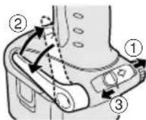
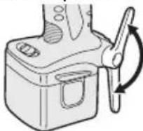
To set the belt hook angle position
- Slide the belt hook lock lever ① and hold it to unlock the belt hook.
2.Pull the belt hook from storing position ② and set it as desired angle.
-
Release the belt hook lock lever to lock the angle of belt hook.
-
Make sure the belt hook is firmly locked ③ Also make sure the belt hook is firmly locked into position.
The belt hook cannot be locked in this position. Firmly lock it into position before use.
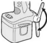
To return the belt hook to the storing position, Follow step 1. and 2. above, then lower the belt hook.
To secure the lock, follow 3 and 4 above.
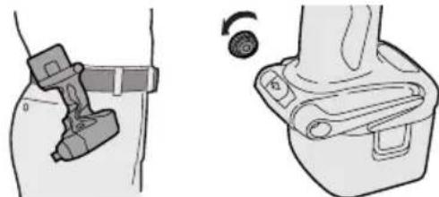
To change the belt hook location side
The belt hook can be attached to either side of the unit.
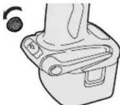
- Set the belt hook at storing position.
- Loosen the screw turning it counterclockwise, using a coin or a flat blade screw driver.
- Take out the belt hook and insert into the other side of the slot on the main unit.
- Fasten the screw firmly, turning it clockwise.
The belt hook can be taken out from the main unit only when it is at storing position.
Additional Power Control Functions
Quick Reference for Features and Functions
■ Impact power mode select: A (See p.6.)
→ This unit is equipped with impact power mode button. By pressing impact power mode
button, softimpact mode, medium impact mode and hard impact mode can be selected (3 settings).
- Please use this together with digital clutch setting.
Digital clutch: (See p.7.)
This unit is equipped with the digital clutch function.
The driver rotation will stop when the set clutch load is reached.
- Please use this together with impact power mode select.
This digital clutch is not intended for controlling the accuracy of the fastening torque.
Example application not to be used;
- To control the shut-off torque used to tighten screws and bolts for manufacturing and assembly.
Do not use the digital clutch when tightening screws with a low tightening torque into materials, such as thin plastic.
Example applications not to be used;
- When tightening screws into lightweight steel sheet which thickness is 0.8mm or less.
- When tightening screws into soft surface materials, such as interior finish - ing materials.
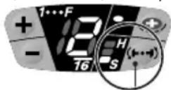
One-shot impact function : C (See p.7.)
Set the one-shot impact function to tighten screws slightly to adjust the screw head flush to the material surface. Select the clutch setting to match the application. This is used when readjust -ing is continuously required.
The driver automatically rotates approximately half round and stops each time the trigger switch is depressed. (For bolts, it stops after approximately 5 impacts.)
Within 1 sec. after the trigger switch is released once, if it is depressed again, the one-shot impact function will automatically operate.
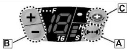
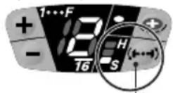
■ Indication lights on the control panel
The indication lights will go off in the following cases.
The driver is not operated for 5 min.
- When the battery is replaced.
Depressing the trigger switch again, then indication lights go on in the previous condition.
Main recommended applications and setting guidelines.(see p.11.)
- Be sure to set the impact power mode and digital clutch to match the material and screws being used for the application.
- Adjust the settings from low to high while checking them to settle on a final setting for impact power mode select and for digital clutch setting.
- When driving screws into wood, use the screws of less than 90mm long and avoid knots of wood materials.
*One-shot impact function requires the impact power mode select and digital clutch settings.
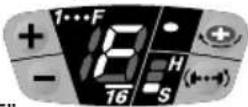
Impact Power Mode Select
- Selecting the impact power among 3 modes (Soft, Medium, Hard).
Impact power mode button
Press the impact power mode button to set it. The mode changes to hard, medium, or soft each time the button is pressed. To use automatic mode shifting, press the button for a period (0.6 sec. or more). It is recommended that the impact power mode select be used together with the digital clutch setting and one-shot impact function.
The driver is preset to "hard" impact mode setting when shipped from the manufacturer.
Recommended work guideline table
When maximum power is required in each impact mode, set the clutch to the "F" mode.
| Impact Power mode Display | Recommended Application |
| H Approx. 2,800R.P.M.(Max.) | For hard impact power mode. • Fastening long wood screws. • Tightening bolts when installing devices, etc. |
| M Approx. 2,500R.P.M.(Max.) | For medium impact power mode. • Fastening small diameter screws into hard materials. • Driving machine screws when installing devices. |
| S Approx. 2,000R.P.M.(Max.) | For soft impact power mode. • Installing gypsum board. • Installing soft metal window flame. • Installing interior finishings. |
One-Shot Impact Function
This function helps adjust the screw head flush to the material surface.
The driver rotates half round* and automatically stops each time the trigger switch is depressed while tightening a screw. The driver will give impact about 5 times and automatically stop while tightening a bolt even though the trigger switch is depressed. The one-shot impact function is also available in reverse rotation. The impact force is set by the impact power mode select and digital clutch settings.
NOTE:
- The one-shot impact function operates after impact. Over-tightening may occur when tightening screws into soft materials as the tool does not impact.
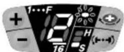
Using the one-shot impact function
When the trigger switch is released and it is depressed fully within 1 sec., one-shot impact function operate. Then the one-shot impact LED light will blink.
Wait at least 1 sec. after trigger is released, not to operate the one-shot impact function.
Keeping the bit head to the screw head to use this function.
When the screw is sticking up quite a ways, increase the clutch setting.
Using the one-shot impact function continuously
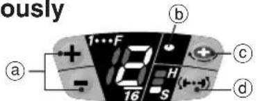
Refer to the guideline table (See p.11.) and check the application. Press the impact power mode button (d) to select the setting. Select the digital clutch setting (a) that matches the application. To set the one-shot impact function, press the button (c) then light (b) turns on. Depress the trigger switch fully to adjust the screw tightening until the one-shot impact function operates. The amount of screw fastening rotation by one-shot impact will differ depending on the impact power mode and digital clutch settings. To turn off the one-shot impact function, press the button (c) once more then light (b) turns off.
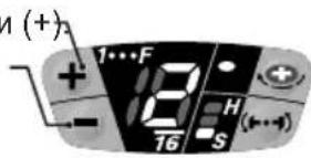
Digital Clutch
The digital clutch automatically stops the driver rotation when the load is reached to the select setting. Depress the trigger switch fully to tighten the screws until the digital clutch operates. If the screw head is not flush to the material surface, release the trigger switch and then within 1 sec. depress it again. This will operate the one-shot impact function.
To select digital clutch setting.
Refer to the guideline table and check the application. (See p.11.)
Press the impact power mode button to set the impact power mode. (See p.6.)
Press the digital clutch setting buttons and select the setting to match the application.
The digital clutch setting increases each time (+) button is pressed.
The setting decreases each time (-) button is pressed.
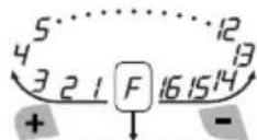
Digital clutch setting range
Setting is available from 1 to 16 stages to match the application.
Keep pressing the and button 0.6 sec. or more will automatically shift the setting to "F". (Digital clutch is turned off in the each impact power mode.)
Turn off the digital clutch.
Press the digital clutch setting button to change the setting to "F."
NOTE:
- When selecting the digital clutch setting, first start at a low setting and a soft impact mode. Then gradually select to higher settings. Try on a scrap piece of the material to determine the best setting beforehand. Too high setting could result in over-tightening of the screws.
- Keep the trigger switch fully depressed while tightening one screw to operate the digital clutch. Do not release the trigger switch until digital clutch operates.
The clutch setting remains the same when the driver is changed from forward to reverse rotation while the clutch is set. To drive in reverse at full power, change the clutch setting display to "F" and turn off the digital clutch.
The driver is preset to "F" full power (digital clutch is off) and the one-shot impact function is off when shipped from the manufacture.
CAUTION:
- When the clutch is set to 1 or 2 stage, the impact power mode is automatically set at "Soft" impact mode regardless of the impact power mode select display setting.
- When the clutch is set to 3 or 4 stage, the impact power mode is automatically set at "Medium" impact mode even in the "Hard" impact mode display setting.
| Clutch setting and operating impact force | Impact Power Mode Display | ||
| 1.2 | 3.4 | 5~16 | |
| Soft Medium Hard | H | ||
| Soft Medium Medium | M | ||
| Soft Soft | S | ||
Important remarks when using the digital clutch and one shot impact functions
The digital clutch setting could be used only as a guideline. The suitable setting will vary depending on the hardness of the material, the force being applied to the tool, and the type of screw.
- Uneven material hardness could result in less-tightening or over-tightening depending on the position on the material.
- If the battery pack capacity is low, the driver might not fully tighten the screws.
Usage
- When driving screws into wood, use the screws of less than 90mm long and avoid knots of wood materials.
- Be sure to set the impact power mode and digital clutch to match the material and screws being used.
- When selecting the digital clutch settings, start from low to high stage while checking the setting (on a scrap piece of the material) to determine the best setting. Too high setting could result in over-tightening of the screws.
Depress the trigger switch fully when using
the digital clutch and/or one-shot impact function during one period of operation. Using low speed by trigger switch could result in a discrepancy in work results.
- When using the digital clutch, depress the trigger switch fully until the digital clutch operates. Do not release the switch until the rotation stops. Releasing the switch to stop rotation before finishing tightening a screw could result in not being fully tightened. (If this happens, start from the beginning of fastening.)
Applications not recommended for these functions
- Tightening screws into easily breakable materials, such as thin plastics.
- Tightening screws into lightweight steel sheet which thickness is 0.8mm or less.
- Tightening TEKS screws into soft surface materials, such as interior finishing materials.
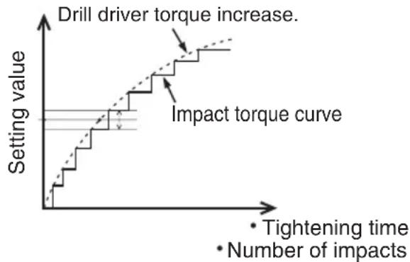
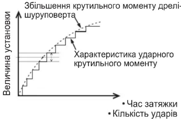
Reason: The impact function is a mechanical sidewalk impact. The tight -ening torque increases instantly step by step when the hammer impacts. Therefore, fastening torque of impact driver is not generally increased as a drill driver. (The accuracy also varies depending on the material.)
Impact torque curve
Tightening torque (load)
- To control the tightening torque for screws and bolts during factory manufacturing and assembly.
Reason: The digital clutch uses a sensor and microcomputer to deduce the load from the number of motor rotation between impacts and then stop the rotation when the load reaches to the set clutch load. To deduce this load requires at least 4 or 5 impacts, This is not suitable for materials which requires a low tightening load, as impact may not occur 4 or 5 times.
The digital clutch cannot operate accurately when the connecting surface material is soft and the fixing base sheet is hard. Example applications for which it cannot be used;
- Attaching gypsum board on hard wood.
- Tightening screws with different lengths, diameters, thread pitches, etc., even if they are the same type of screw.
For Appropriate use of Battery pack
Ni-MH Battery pack (EY9201)
- Charge the Ni-MH battery fully before storage in order to ensure a longer service life.
- The ambient temperature range is between 0^ (32^) and 40^ (104^) . If the battery pack is used when the battery temperature is below 0^ (32^) , the tool may fail to function properly. In that case, charge the battery until charging is completed for appropriate functioning of the battery.
- When battery pack is not in use, keep it away from other metal objects like: paper clips, coins, keys, nails, screws, or other small metal objects that can make a connection from one terminal to another. Shorting the battery terminals together may cause sparks, burns or a fire.
- When operating with a Ni-MH battery pack, make sure the place is well-ventilated.
Battery Pack Life
The rechargeable batteries have a limited life. If the operation time becomes extremely short after recharging, replace the battery pack with a new one.
Battery Recycling
ATTENTION:
For environmental protection and recycling of materials, be sure that it is disposed of at an officially assigned location, if there is one in your country.
Charging
NOTE:
When you charge the battery pack for the first time, or after prolonged storage, charge it for about 24 hours to bring the battery up to full capacity.
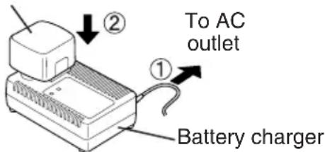
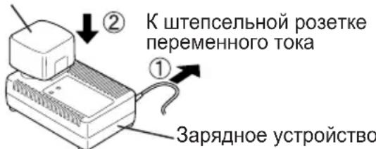
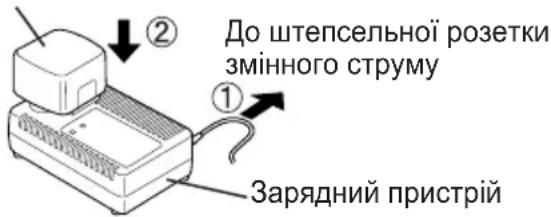
Battery charger (EY0110)
- Plug the charger into the AC outlet.
NOTE:
Sparks may be produced when the plug is inserted into the AC power supply, but this is not a problem in terms of safety.
- Insert the battery pack firmly into the charger. Battery pack
-
During charging, the charging lamp will be lit. When charging is completed, an internal electronic switch will automatically be triggered to prevent overcharging.
-
Charging will not start if the battery pack is warm (for example, immediately after heavy-duty operation).
The orange standby lamp will be lit until the battery cools down. Charging will then begin automatically.
- When charging is completed, the charging lamp will start flashing quickly in green color.
- When in any of the conditions that battery pack is too cool, or the battery pack has not been used for a long time, the charging lamp is lit. In this case charging takes longer to fully charge the battery pack, than the standard charging time.
- If a fully charged battery pack is inserted into the charger again, the charging lamp lights up. After several minutes, the charging lamp may flash quickly to indicate the charging is completed.
- If the charging lamp does not light immediately after the charger is plugged in, or if after the standard charging time the lamp does not go off, consult an authorized dealer.
NOTE:
- When charging a cool battery pack (below 5^ (41^) ) in a warm place, leave the battery pack at the place and wait for more than one hour to warm up the battery to the level of the ambient temperature. Otherwise battery pack may not be fully charged.
Cool down the charger when charging more than two battery packs consecutively. - Do not insert your fingers into contact hole, when holding charger or any other occasions.
CAUTION:
To prevent the risk of fire or damage to the battery charger.
- Do not use power source from an engine generator.
- Do not cover vent holes on the charger and the battery pack.
- Unplug the charger when not in use.
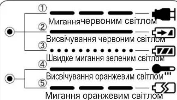
IV. LAMP INDICATIONS
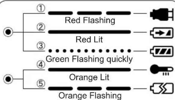
① Charger is plugged into the AC outlet. Ready to charge.
② Now charging
③ Charging is completed.
4 Battery pack is warm. Charging will begin when temperature of battery pack drops.
⑤ Charging is not possible. Clogged with dust or malfunction of the battery pack.
V. MAINTENANCE
Use only a dry, soft cloth for wiping the unit. Do not use a damp cloth, thinner, benzine, or other volatile solvents for cleaning.
VI.TIGHTENING TORQUE
The power required for tightening a bolt will vary, according to bolt material and size, as well as the material being bolted. Choose the length of tightening time accordingly. Reference values are provided below. (They may vary according to tightening condition)
Factors Affecting Tightening Torque
The tightening torque is affected by a wide variety of factors including the followings. After tightening, always check the torque with a torque wrench.
1) Voltage
When the battery pack becomes nearly discharged, the voltage decreases and the tightening torque drops.
Bolt Tightening Conditions
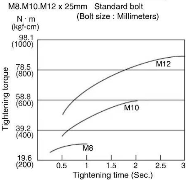
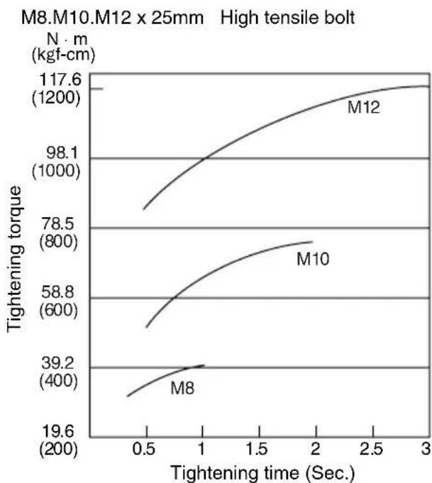
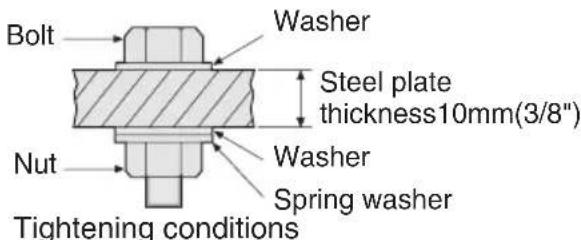
The following bolts are used. Standard bolts:Strength type 6.8 High tensile type 12.9
2) Tightening time
Longer tightening time results in increased tightening torque. Excessive tightening, however, adds no value and reduces the life of the tool.
3) Different bolt diameters
The size of the bolt diameter affects the tightening torque.
Generally, as the bolt diameter increases, tightening torque rises.
4) Tightening conditions
-
Tightening torque will vary, even with the same bolt, according to grade, length, and torque coefficient (the fixed coefficient indicated by the manufacturer upon production).
-
Tightening torque will vary, even with the same bolting material (e.g. steel), according to the surface finish.
- Torque is greatly reduced when the bolt and nut start turning together.
5) Socket play
Torque is lowered as the six-sided configuration of the socket of the wrong size is used to tighten a bolt.
6) Switch (Variable speed control trigger)
Torque is lowered if the unit is used with the switch not fully pulled out.
7) Effect of Connecting Adaptor
The tightening torque will be lowered through the use of a universal joint or a connecting adaptor.
VII. ACCESSORIES
Use only bits suitable for size of chuck.
VIII. APPENDIX
MAXIMUM RECOMMENDED CAPACITIES
| Model | EY7202 | |
| Screw driving | Wood screw | φ 3.5 - φ9.5 mm (1/8" - 3/8") |
| Self-drilling screw | φ 3.5 - φ6 mm (1/8" - 1/4") | |
| Bolt fastening | Standard bolt : M6 - M12 High tensile bolt: M6 - M10 | |
GUIDELINE TABLE
| Fixing material (thickness) | Base material | Screw (Size) | Impact power mode | Clutch setting stage reference | ||||||||||||||||||||
| H M S | 1 | 2 | 3 | 4 | 5 | 6 | 7 | 8 | 9 | 10 | 11 | 12 | 13 | 14 | 15 | 16 | ||||||||
| 2×4" Material 2 | ×4" Material | Drywall screw φ4.2×75 (3/16"×3") | ● | ● | ||||||||||||||||||||
| Plywood 12 mm (1/2") | 2×4" Material | Drywall screw φ3.8×28 (1/8"×1-1/4") | ● | ● | ● | |||||||||||||||||||
| Gypsum board 12 mm (1/2") | 2×4" Material | Drywall screw φ3.8×28 (1/8"×1-1/4") | ● | |||||||||||||||||||||
| SPC 1.2 mm (1/16") | SPC 1.2 mm (1/16") | Self-drilling screw φ4×1.3 (3/16"×1/2") | ● | ● | ||||||||||||||||||||
| 2×4" Material 2 | ×4" Material | Coach screw φ9×50 (3/8"×1-15/16") | ● | |||||||||||||||||||||
NOTE:
- When screwing TEKS screws into hard materials, use the lighter digital clutch's setting to avoid slippage which may chip or damage the screw. For the final tightening, use the one-shot impact function.
- Depending on the type of screw or the hardness of the material, the screw may not be completely flush with the surface. When working with cabinet boards or other more decorative materials where screws need to sit flush on the surface, use the lighter digital clutch's setting to avoid damaging the material, and then finish using the one-shot impact function.
IX. SPECIFICATIONS
MAIN UNIT
| Model EY7202 | ||
| Motor DC Motor 12 V | ||
| No load speed | soft mode 0 - 2000 /min | |
| medium mode 0 - 2450 /min | ||
| hard mode 0 - 2600 /min | ||
| Maximum torque 120 Nm (1220 kgf-cm, 1060 in-lbs.) | ||
| Impact per minute | soft mode 0 - 2000 /min | |
| medium mode 0 - 2500 /min | ||
| hard mode 0 - 2800 /min | ||
| Overall length 167 mm (6-9/16") | ||
| Weight (with battery pack : EY9201) 1.85 kg (4.1 lbs) | ||
BATTERY PACK (EY9201 is included with shipment.)
| Model EY9201 E | Y9200 | EY9106, EY9107 | EY9101 | EY9001, EY9006 | |
| Battery voltage 12 V DC (1.2 V × 10 cells) | |||||
| Storage Battery | Ni-MH Battery | Ni-Cd Battery | |||
| Capacity | 3.5 Ah | 3.0 Ah | 2.0 Ah | 1.7 Ah | 1.2 Ah |
BATTERY CHARGER
| Model | EY0110 |
| Rating | See the rating plate on the bottom of the charger. |
| Weight | 0.78 kg (1.72 lbs) |
| Charging time | 55 minutes (EY9201) |
NOTE:
- Do not charge "Y" type Ni-Cd battery packs.
- For applicable battery packs to this charger, see the label on the charger or the latest general catalog.
ONLY FOR U.K.
X. ELECTRICAL PLUG INFORMATION
FOR YOUR SAFETY PLEASE READ THE FOLLOWING TEXT CAREFULLY
This appliance is supplied with a moulded three pin mains plug for your safety and convenience.
A 3 amp fuse is fitted in this plug.
Should the fuse need to be replaced please ensure that the replacement fuse has a rating of 3 amp and that it is approved by ASTA or BSI to BS1362.
Check for the ASTA mark or the BSI mark on the body of the fuse.
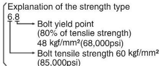
If the plug contains a removable fuse cover you must ensure that it is refitted when the fuse is replaced.
If you lose the fuse cover the plug must not be used until a replacement cover is obtained.
A replacement fuse cover can be purchased from your local Panasonic Dealer.
IF THE FITTED MOULDED PLUG IS UN-SUITABLE FOR THE SOCKET OUTLET IN YOUR HOME THEN THE FUSE SHOULD BE REMOVED AND THE PLUG CUT OFF AND DISPOSED OF SAFELY.
THERE IS A DANGER OF SEVERE ELECTRICAL SHOCK IF THE CUT OFF PLUG IS INSERTED INTO ANY 13 AMP SOCKET.
If a new plug is to be fitted please observe the wiring code as shown below.
If in any doubt please consult a qualified electrician.
IMPORTANT:
The wires in this mains lead are coloured in accordance with the following code:
Blue:Neutral
Brown: Live
As the colours of the wire in the mains lead of this appliance may not correspond with the coloured markings identifying the terminals in your plug, proceed as follows.
The wire which is coloured BLUE must be connected to the terminal in the plug which is marked with the letter N or coloured BLACK.
The wire which is coloured BROWN must be connected to the terminal in the plug which is marked with the letter L or coloured RED.
Under no circumstances should either of these wires be connected to the earth terminal of the three pin plug, marked with the letter E or the Earth Symbol 1一
How to replace the fuse: Open the fuse compartment with a screwdriver and replace the fuse and fuse cover if it is removable.
This apparatus was produced to BS800.
LED-PRODUKT DER KLASSE 1
VORSICHT: SEHEN SIE NICT IN DEN STRAHL.
VerwendendesRiemenhakens
WARNING!
(Framat, Last, Bakat)
VIKTIGT:
Skala for digital clutch
CBeToOnoNHOe H3dJIne Knacca1
BHHMaHHe:HE CMOTPETb HA JIyU.
Kak monb30BaTbCnNOaHbIM KpIOKOM
OCTOPOXHO!
- Y6eIInTeCb, yTO NOrCHOn KpIOK HAdEJHO npIKpeJIeH K OCHOBHomy 6nOky npu NOMoUINnoTHO 3aTAYtOrO BnHTa. EcN NoAChOH KpIOK He npIKpeJIeH HAdEJHO K OCHOBHomy 6nOky, KpOK MOKeT OToITN U OCHOBHO 6nOK MoKeT yNaCTb. 3To MOKeT npINBeCTN K HeCuaCTHOMy CnyaIO INI TpaBMe.
- PepnoDnueckn npOBepaIte BnHT Ha nnOTHOCTb. Ecnn obHApxKntcra, yTO OH HennlOTHo 3aTaryr, nnotHO 3aTAHnte erO.
- Y6eIntecb, yTo nOraCHOn KpIK IIOTHo HnadeJxHO npIKpeHEn K NOrCHOMy pEmHOn nnDpyROMy pEMHIO. BHNMaTeJIbHO cneIHTe 3a TeM, yTObbl 6nOK He COCKONb3HyJ C NOraCa. 3TO MoKET npINBeCTN K HeCHaCTHOMy CnyaIO nn TpaBMe.
- Ecnn OCHOBHO 6nok ydepXnBaETC NOCHbIM KpIOKOM, N36beraIte npbIraTb N beratb C HmM. 3TO MOKET pINBECTN K COCKaJIb3bIBaHNIQ KpOKA IN NaDeHNI OCHOBHO 6noka. 4TO MOKET pINBECTN K HechactHOMy CNYaHO NN TpaBMe.
- Ecnn noaHoi KpOHe nCnoB3yeTcya6eNTecb,yTO OH BO3BpaueH B NOIOKeHne dIy XpaHEnn. IoAChO KpOK MoXe 3aueNtbcr 3a yTo-Jn6o. 3TO MOxET npVBecTI K HeCuaCTHOMy CnyaHOnn TpaBMe.
- EcIIN 6JOK NOBEWeH Ha NORCHOM pEmHe npi NOMOUI NORCHO KpIoka, He 3aKpePnIe H Hero HacaIK WypynOBepTa.Obbekt C ocTpbIMN KpOMkAM, TAKOI KAK HacaIka IJIa CBepJeHnM MoKET nPiBecTI K HeCuaCTHOMy CnyauIO INI IN TpaBMe.
YTO6bI yCTaHOBNTbByrOJI NOBOPoTa NORCHOrO KpIOKa
1.CBnBte pbyar Kcaun NoaCHoro Kpoka ① n yepKnaIte erO, T06bpa36nKnpoBaTb NOACHO KpIK.
- Notaryte noarchoi KpOK n3 noLoXeHnA dJa XpaHeHnA ② N yCTaHOBnte ero nD HyXhblm yrIOM.
-
OTnyctnte pbuhar ФИКСАЦN NOЯСHOrO KpIOKa, ЧТБЛ 3aФИКСИРОВАТ bYrOЛ ПОВОТА NOЯСHOrO KpIOKa.
-
y6eDntecb, yTO nOraCHo KpOK npOuHO 3a6nokupoBaH ③. TaKKe y6eDntecb, yTO nOraCHO KpOK npOuHO 3a6nokupoBaH B
IPOCHON KPOK He MoXeT 6bITb 3a6nOKnpOBaH B DaHHOM N0JoxKeHN. IpepeNcNoJIb3OBAHNem npOuHO 3a6nOKnpynte erO B HUxHOM N0JoxKeHN.
UTo6bI BepHyb IIOCHOH KpOK B NOJIOXeHne DnI XpaHeHn, CNeDyHTe BblweONHbIM DeNCTBnM NYHKTOB 1 n 2, 3aTEM ONyCTnTE NOCHO KpOK. UTo6bI 3a6NkOpiOBaTb QHKcatOp, CNeDyHTe BblweONHbIM DeNCTBnM NYHKTOB 3 n 4.
4to6bln3MeHnTb CToPOHy pa3MeueHnIIOEHOKpOka
IPOAHOK KPIOK MOKeT 6bITb pa3MeUeH HaJIIO60n3 CTOpOH 6JIOka.
1.YctaHOBtTe NOrCHoN KpK B NoNoXeHne JnXpaHeHn.
2.Ocna6bTe BnHT, Bpauaeraero npOTNB YacBOB CTpeJKN, INCNOJb3yra dIa 3TOro MOHETKU NIN PLOCKYIO OTBepTKY.
3. BbHbTe NORCHON KIOK IN BCTaBbTe eRO B DpyryIO CTOPOHY OTBepCTnHa OCHOBHOM 6NoKe.
4.ПNotHO 3aTЯHnTe BnHT,ВpaUaJ erO no YacOBoN CTpeJIke.
IPOCHOH KPIOK MOKET 6bITb BbHyT n3 OCHOBHO 6noka TOnbKO eCIN OH HAXOINTcB NOJIOXeHn Dn XpaHeHn.
DOnoJIHnTeJIbHbIe cyHKcnn KOHTPOJIaMOUHOCTN
KpaTkoe pyKOBOcTBo NO CBOIcTBaM N cyHKnA
BbI6oppeXIMMaMOUHOCTuYdApA(CM. cTp.107.)
→Данhoe yctpoiCtBO OCHaUeHO KHONKOB bIbopa peKIMa MOuHocTn ydapa.HaxaTneM KHOKN Bblbopa peKIMa MOuHocTn ydapa, MOxET 6bITb BblbpaH MraKn peKIM ydapa, cpeHN pEXm ydapa n JecTkni peKIMydapa (3 yCTaHOBKn).
* IoxaanyuCTa, nCNoB3yUte 3OT pexkMBecTe C yctAHOBKOn UnpoBOm MyTbl.
LcnpoBa myta: B (Cm. ctp. 108.)
→Данhoe yctpoiCTBO OCHaIeHO ΦyHKUneu UΦpOBoMуΦTbI.
BpaueHne uypynOBepTa 6ydt octaHO Bnnpn DOCTNXeHN yCTaHOBNEHHO 3HaueHn Hary3Kn Ha MyDy.
*IoxaanyuCTa,ncnoB3ynte 3TOT peKm BmecTe C BB6opom peKMa MOUHcTn ydapa.
DaanhaunpobarmytaHe npda3haeHa DnKoHTPOJrTOHOCmMoneHa 3aTAKN.
PpIMep npIMeHnHa, KOtOpoe He DoJxHo NCNoJIb3OBaTbcR:
KoHTpOJa MOMeHTa 3aTJKKn, NcNoJIb3OBAHHORO dIra 3aTJKKu WypynOB u 6oNTOB B npOn3BOIDCTBe n c6OpKe.
He ncononb3yTe uHcpoByo MycTy npn 3aTAAKKe WypynOB C Hn3KNM MOMENTOM 3aTAAKKN B TaKne MaTePnaJbl, KaK PnlaCTMaCCa.
PpIMep npIMeHnKOTOpoe He DoJxHO nCNoIb3OBaTbcR:
- Pn3aTajke uypynOB B JERKNE cTaJIbHbIe IINCTbl, TOJIuHa KOTOpbIX paBHa 0,8 MM MeHee.
- Pn 3aTjXke WypynOB B MaTePnaJIbIC MraKoN NOBepxHOCTbIO, TAKNE KAK MaTePnaJIbI DnB BYHTpeHHei OTJeJKN.
HaxmTe KhoNk yCTaHOBKn CnΦpOBoM MyoTbI N BbI6epnte YcTaHOBky, KOtopa COOTBeTCTByET PnIMHeHIO.
YcTaHOBka CnΦpOBMyΦTbI yBéJIuHNaeTcπPn
KaJDOM HaKATNU KHONKUcTahOBka uOPOBOMyTbI yMeHbIaETcNpN KaJDOM HaKATNUKHONK(-).
Dnana3OH yCTaHOBOK uΦpOBoM MyΦTbI
OCTyNHbI yCTaHOBKn OT 1 Do 16 CTyneHn B COOTBeTCTBn C pImMeHeHnEM.
NoHHa MOUHOCTb
Pn npoJONKHTeHbHom HaxkTnn KHOJOK+N-B TeueHne 0,6cekyHdbI Nn6OJee, ABTomTuYeCKn BKJIOHTcYCTaHOBKa "F". (Unpobar MyTa OTKnIOHaETcB KaXdOM pexIme OINHOHOrO yDapa.)
BbIKIouHeHne cnppOBoMyΦTbI
HaxMITE KONky yCTaHOBKn UnpoBou MyTbI DnI N3MeHeHn yCTaHOBKn B 3HaueHne "F".
ПРИМЕЧАНЕ:
- Pn BbIbope yCTaHOBKn CUnpOBoM MyfTbi, CHaHana HaHInTe C HN3KoY cTaHOBKn N peXIMa MraKoro Ydapa. 3aTeM NoCTeNEHHo BbIbpaIte 60Jee BbcOKne yCTaHOBKn. 3apaHee nonpo6ynte nx Ha oTpe3Ke MaTePnAna Jn OnpdeJeHnHaNlyUwey cTaHOBKn.CnUkOM BbcOKa YcTaHOBKa MoXeT npVBecTN K Upe3MePHo 3aTJxKke Wypynob.
- YdepKNaTe NyCKOBn BbIKNoaTeNb NOHocTbIO HaxaTbIM npn 3aTjXke OndHO Wypyna, UTo6bI NCNoJb3ObaTb CnpPObyo MypTy. He OTnyckaTe NyCKOBn BbIKNoHaTeNb, noka pa6oTaet cnpPOBaMyfTa.
- YctaHOBka MyΦTbI OCTaETcnaPexKHe, ecnN WypynOBepT nepeKIOuayetc n3 BpaueHnBnepeHa BpaueHne Ha3ad npn ycTaHOBJIeHHoMyΦTe.ДЯ BpaueHn Ha3ad C NOHON MOUHOCTbIO N3MeHNTe 3NaueHne yCTaHOBKn Ha "F" N BBIKNUHTe cnpPOByo MyΦTy.
UpynoBepnepBOHaayabHo yCTaHOBneH B3NaueHne NOnHO MOuHOCTN “F" (UnpOBAMyoBbIKNoeHa) OTKIOUeHHyO OyHKUO ODNHOYdapa npN OTnpaBKe OT pON3BOOnTeJI.
BHIMAHNE:
- Ecni MyfTa yCTaHOBHeHa B CTyPeHb 1 nnn 2,peKIM MOUHOCTn yDapa aBTOMaTNUeCKn yCTaHABJINBaETcB "MrkN peKIM yDapa He3aBNCmO OT yCTaHOBKn 3HaueHnpeKIMMa MOUHOCTn yDapa.
- Ecnn MyfTa yCTaHOBHeHa B CTyneHb 3 nnn 4, pexnM MoIHOCTn yapa aBTOMaTHueCKn yCTaHaBnBaETcB "CpeHn" peXm
yda pa daKe npu yctaHOBe 3HaueHnpeKIma MoUHOCTn yda pa "KeCTkn"
Cpok cnyx6bI 6aTapeHoro 6Joka
AkkymyIaTOPhIe 6aTapeu IMeIoT
OrpaHnueHHbI cPOK cnYk6bl. Ecnn nocne
3apJKn BpeMf yHKUHOHPOBaHnCtAHOBITcR
4pe3MepHo KOpOTKm, 3aMeHnTe 6aTapeHbI
6lOk Ha HOBbI.
Yttnn3aun 6atapen
BHIMAHNE:
B ueJx 3aunTbI OKpykaIoUeN cpebl I yTuIN3aUIM MaTePnAIOB, y6eINTEcB, UTO OHa yTuIN3InPOBaH B OOnuAnbHO npEHa3NaueHHom MeCTe, eCNI TaKOBbie ecTB B BaWei cTpaHe.
3apяdka
ПОНМЕЧАНЕ:
Pn nepBoN 3apAKe 6aTapeHOro 6Joka,
IIN NOCNE DInTeBHO XpaHEnn, 3apJkaIte ero B TeueHne Okono 24 YacOB, UTO6bl DOBeCTN 6aTapeIO Do NOHN 3apJdHOEMKOCTN.
3apndnoe yctpoiCTBO (EY0110)
- BkIIOHTe 3apAHOe yCTpoiCTBO B WTeNCEbHyo po3ETky nepemEHoro TOka.
ПОНМЕЧАНО:
Pn PNOKIOUeHn WTeNCEJbHOB BNKn K NCTOUYHKY NITaHNA nepemEHORo TOKa MOrYT NOBtBCrNCKpbI, HO 3TO He npedctabJAreT npobemy C ToUK 3peHna 6e3OnacHOCTn.
2.ПЛOTHO BCTaBbTe 6aTapeHbI 6JOKВЗapdHoe yCTpoINCTBO.
BaTapeHbI 6JIOK
3.BoBpem3apAdkn6ydtropeT lamnoqka 3apAdkn.
Pocne 3aBepseHn 3apAKn aBTOMaTHueckn cpa6oTaet BHyTpEnHHN 3JeKtpoHHbI nepeKIOuataeIb, npedOTBpaaJype3MepHyIO 3apAky.
3apka He NaHcHcTc, ecn6bTaapeHbI 6bnok cnsKOM ropnyi (Ha npimep, HenocpeDCTBeHHo Nocne cyHKUHOHPOBaHn npn 60nbwo Harpy3ke).
OpaHkeBaIaMNoUkapeXIMaOxNlaHnna 6ydet ropeTdoTexnop,noka 6aTapeR He octbIHET.3aTeM 3apJkHauchetcra ABTomatNuYeCKn.
-
Nocne 3aBepWeHn 3apAn KaamnoUka 3apAnn HauHET 6bICTPO MrrA Tb 3eJeHbIM CBTOM.
-
PnI NIO6OM n3 ycNOBn, KOrda 6atapeHbI 6NOK CnIIKOM XOLOHbI, IIN6o 6atapeHbI 6NOK He NCNoJIb3OBaIcR dInTeJbHOe BpEm, NaMNoUka 3aprKn 6ydt ropeT. B TakOM cnyae 3aprKa 3aMomet 60one npOdoJXnTeJbHOe BpEm, NOka 6atapeHbI 6NOK noHocTbIO He 3apraNTcR, B CpaBHeHH CO cTaHApTHbIM BpEmHeM 3aprKn.
-
Ecnn nolnoctbIO 3apjxeHHbI 6aTapeHbI 6nOK cHOBA BCTaBNTb B 3apJdHoe yCTPOINCTBO, 3arOpNTcJaMNoUka 3apJdKN.
Yepe3 HeckoIbKO MmHyT IaMNoUka 3apAdkn MOKeT Haatb 6bICTPO MmraTb, NOKa3bIBaJ, YTO 3apAdka 3aBepWeHa.
- Ecnn JAmnoka 3apJKn He 3aRopTcHn HEnocpeDCTBHeHNO nOcne BKNIOueHn 3apJHO yCTpOuCTBa, INe ecn JAmnoka He NOrachET NO nCTeueHn CTaNapTHoro BpeMeHN 3apJKn, ObaPHTecb B yNOLHOMOeHHbI CepBnCHbI ueHTp.
ПРИМЕУAHNE:
-ПиЗзэрдкхлонго6ат apeHoro 6noka(c TempepaTypoi Hxke 5^ (41^) BTeTnOMMeCTe,OCTaBbTe6aTapeHbI 6JOKB3TOMMeCTeNIOQxdTe6oJee ODHoro Yaca,NOKA6aTapeHarpeetcdo yPOBnA TeMnePaTypbl OkpykaIoUe n Cpebl.B npOTNBHom clyuae,6aTapeHbIM 6JOKMOKETHe3apdntcnoJIHOCTbI.
- OxanaIte 3apAnHoe yCTpoiCTBO npn nocJeIOBateIbHOJ 3apJKe 6Oonee Yem DByx 6atapeHbIX 6lOKOB.
He BCTaBnIte Baun naIbCuI B KOHTaKTHbIe OTBepCTNu, KOrDa Bbl DePKeTc 3apJHoe yCTpOInCTBO,a TaKKe B Dpyrnx Cnyuax.
BHIMAHNE:
IpypeIOBpaueHn npCKa noKapa nn NOBpeXDeHn 3apAnHO yCTpoNCTBa.
He nCnoJb3yIte B KaueCTBe NcToUHnKa nHTaHn rHepeaTOP DnurTaTeJI.
- He 6IokpyTe BeHTnIaIIOHHbIe OTBepCTnHa 3apJHOM yCTpOINCTBe n 6aTapeHOM 6Ioke.
BbIKHouHe 3apAHOe yCTPOIcTBO n3 WTeNCEJIbHOJ po3ETKn, eCIN OHO He NCNoJIb3yETcJ.
IV.CBETOBblE INHdNKATOPbl
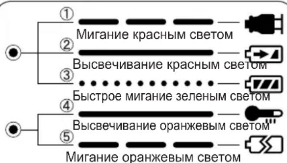
① 3apAnHoe yCTpoiCTBO NOKlnHoyeHO K WTeNcIbHOn po3eTke nepemEHoro TOka. TOTOBK3apJKe.
②BbInonHReTc3apRka.
③ 3apraKa 3aBepweHa.
④БатAPEинь 6лOK ropayn.3apяdka NaHETcK, KOrda TempepaTypa 6batapeHoro 6Ioka ynaTeT.
⑤3apKa HeBO3MOxHa. BaTapeHbI 6JIOK 3acOpEn NblbIO ININ HeNCpPaBeH.
V. OBCJNYKBAHNE
Длг npotnpaHn yctpoiCTBa nCNoIb3yInTe cyxyu Mrgkyu TkaHb. He nCnoIb3yInTe dIra OUNCTKBIAJHXHy TO KaHb, pa36abNTeJIb, 6eH3IN INI npOue neTyue pactBopnteIN.
VI.KPYTAYI MOMEHT 3ATJKKN
Cnla, Heo6xOdIma JIJI 3aTJkN 60JTA MOKeT OTnUaTbC8 B 3aBucmocTn OT MaTePnAna 60JTa N erO pa3Mepa, a TaKke OT MaTePnAna, KOtOpbIK CKpePNIEcTc. COOTBeTCTBeHNO Bbl6uPaETc4IINTEJIbHOCTb BpEmHn 3aTJkN. HxKe IpeDCTabJIeHbI peKOMeHdyEmbie 3HaueHn. (Ohn MOryT MeHrTbcR B 3aBucmocTn OT YcNoBn 3aTJkN.)
IX TEXHnueCKNE XAPAKTEPNUCTNKN
OCHOBHOE YCTPOICTBO
- WypynOBepT He BnKOpNCTOByeTBcH npotra 5 XBUNH.
3amHeHo 6aTapeKo.
Pn noBtOPhOMy HATNCKaHHi NyCKOBORo BmKaua, IHnKaTOpN 3aRopYbC8 B nonepdHbomy pekmi.
OchOBHI BnKOpNCTaHH, zo peKOMeHdyIOTbCЯ i Bka3iBKN no yctaHOBkax. (ДиВ.стор. 123.)
- IpekeKaHTeCg, 10 Bn BCTaHOBN pexm NotyXHoCTi ydApY i uppOBy MyfTy y BiNobIDHOCTI DO MaTePiany i wypynib, kki BnKOpNCTOByOTbCdI DaHOro 3acToCyBaHHa.
BidperyIIOte yCTaHOBky BID Hn3bKOIO DO BVCOKOI, NpeBipraOHy IX Npeed TUM, JK BCTaHOBTN B JAKoCTIOCTaTOHOOY UCTaHOBKN DЯ pEXKIMy NOTyXHOCti yApy i DIA YCTaHOBKn CnΦpOBoi MyΦTn. - Pn 3aBnHcyBaHHi Wypynib y DepeBO, BnKOpNCToBnyTe WypynI DOBXNHO MOHe96 90 MM i YnKaaiTe cykib y DepeB'HNX MaTepiJax.
*FyHKiO OINHOHOro yIapy noTpe6ye Bn6Opy pexmMy nOtJxHocTi yIapy i yCTaHOBKn UΦpOBoI MyΦTN.
Bn6ip pexmnynoTyXhocti ydapy
Bn6ip nOtjxHocti ydapy 3 3 peKmIB (M'kni, cepenHni, KOpctKn).
KhONka peXmMy nToTyxHocTi ydApy
HaTnCHiB KhONkpy pexIMy NOTyXHocTi ydapy, 06 BCTaHObUTn Ioro. PexIM 3MiHIOeTBcA Ha JOpCTKn, cepedHi a6o M'KKn KOxHOrO pa3y, KOJI Na HTnCKaETbCn KHONka.ДЯ BnKOpNCTaHHa peXIMy ABToMaTHUHOr OpeMnKaHHa, HATnCHiB KhONkHa DeAkn Yac (0,6 cek Ta 6IbWe).PekomeHdyETbcR BnKOpNCTOBYBaTN Bn6ip pexIMy NOTyXHocTi pa3OM 3ycTaHOBkoU cHpOBoi MyΦtn i φynKciEo OOnHOHOrO ydapy. 1ypnoBepT nooyKOBO BCTaHObNeHn B "KOpCTKn" pexIM ydAp npi BiDnpabCi BiD BnPo6nka.
Ta6nua Bka3iBok no poboti, zo peKomeHdyIOTbcra
KIO B KOXHOMy 3 peXIMIB yApy NOTpe6yCTbCMAKcImaIbHa NOTyKHICTb, BCTaHOBIT MyΦTy BpeXIM "F".
| Идениця рекиму notyxkhocti уdapy | Викорисань, сю pekomehduyotbcry |
| Приблиз.2800 об/xв (макс.) | Д�� жорст кого рекимуnotyxkn уdapy. • 3агвинчынгаяdoesmwxшурni у deprево. • 3атяжka相关内容пri востановлес мен менизмib, i.T.I. |
BnKOpncTaHn, 0 He peKoMeHdyIOTbcra IaHnx yHKci
3aTjKaIuPyNIB TaKINJaMKnX MaTePiaJax, Rk TOHki INaCTMaCn.
3atjka wypnib B nerki cTanebi nctn, TOBUNHa knx dopibHIOc 0,8 MM i MeHwe.
3aTgka wypyniB TEKS B MaTepiAn 3 M'koIO NOBepxHeO, Taki k MaTepiAn dny BHyTpIshbOrO O3do6JeHH.
PnHHa: YdapHa 6a3yE7bc8 Ha
MexAHCHOMy 6OKOBOMy ydapi. KpyTbHm
Momet 3aTJKK MTTeBO 3pOCTae Wa8
3a WaROM, KOJI Nepopatop 3diChHe
yDap. Tomy, KpyTbHm MOMET 3aTJKK
yDapHoro WypynOBepTa 3pOCTae He NoCTiHo,
kY dpeni-wwypynOBepTa. (ToHicTB taKoX
3MiHOEtBC B 3aJeXHoCTi BiD MaTepiany.)
XapakTepeNTka ydaphHoro KpyTnIbHOro MOMeHTy
KpyTINbHMMOMeHT3aTAXKN(HabaHTaxKeHHA)
-Дя контю мочentу 3atxkN, BUKOPuctaHOrO
ДЯ 3atxkN wypnib Ta 6oTtB y Bnpo6HnTBI ta
36ipci.
PnHnHa: LcnpoBa MyTa BnKOpncTOBye ceHCop Ta MIKpOpoecop DnA BiHImaHHa HabaHTaxKeHH BID YnCna OeptiB OeptaHH MIX ydapAMn i NOTIM 3ynHRe OeptaHH, KOHN HabaHTaxKeHH DOcRHe BCTAHOBJIeHO 3HaueHHa HabaHTaxKeHH MyFTN. DnA BiHImaHH Uboro HabaHTaxKeHH Ntpi6HO k MiHIMyM 4 a60 5 ydApIB. Lc He HEMOXJINBO DnA MaTePIaIb, RKi NOTpe6bYOTb Hn3bkOro HabaHTaxKeHH 3aTAAKK, TAK KMOxHe 6ytN 4 a60 5 ydApIB.
LcnpoBa MyfTa He MoKe ToUHO iIaTI, KaIO KOHTaKtYIOuHa NOBepxH MaTepiAny M'ka,a IINCT fIKcyIOO OCHOBN-TBepn.
PnKJaN BnKOpNCtAHb,ДЯякx ue He MoXHa 3aCTOCOByBaTu:
Kpinnenna rincobux nIIT do TbePdoro depeBa.
3atjka wypnib pi3hoi DOBXHH, diametpy, Wary p3b6n i T.D., HabiTb kIoo BOH npu Cbomy BiIDHOcTbcra OOnHO rna wypniB.
Для наlexног ВИКОпсТаHHЯ 6атapeйног 6лoka
HikeIb-MetanoripnHn 6aTapeHn 6Jok (EY9201)
- Ipeep36epirahnHm NOBHCIO 3apJITb HikeIbMetanoripnHy 6atapeio, 0o6 3a6e3neuHTn
6iIbU TpNBaII N TePmH CnyxK6N.
-ДIANa3OH TempepaTpyn HABKOJIuHbOro cepeIOBua cKnaIaE BiD 0^ (32^) do 40^ (104^)
JaKIO 6aTapeHn 6IOK 6yDe BIKOPNCOTOBYBaTncB npi TemnepaTypi 6aTapei HxKue 0^ (32^) , IHCTpyMeHT MoKe He cyHKioHyBaTu HaJeXHM yHOM. B CbOMy BnnaDky DnAHaJIeXHO r OyHKIOHyBaHHa 6aTapeI NOBHiCTU 3apJITb 6aTapeIO Do 3aBepWeHHaPAnk.
- RaKIO 6aTapeuHn 6Jok He BnKOpNCToByeTbcra, 36epiraTe Ioro nOdaI BiD TaKnx MeTaNEBux peeu, kK cKpiKN, MoHeTN, KJIouHi, ZBxN, Wypyn, a6o IHnx dpi6HNx MeTAneBnx peeu, kKi MOxTy b npN3BeCTN Do KOHTaKTy OndHicI Klemn 3 iHWOIO.
36epirahnHaatapeuHnx 6nokibpa3om moKe CTaTb npunHOIO BUNHKHeHHiaCKp, onikIB a6o nOxKexi.
-Пдчасpo6OTn3HikeNB-MeTaIOriPnIDHM 6aTapeHnM 6JOKOMpekoHaITeCb,IOMiCe do6pe npoBITpOEtbcra.
Tepmin clyx6n 6aataeHoro 6loky
AkymyIaTOpHi 6aTapei MaOb o6MeXeHn TepMin cnyx6n. JaKuo nicn 3apJdku cac yHKIOHyBaHHcTaE HaMipHO KOPOTKM, 3amIHb 6aTapeHn 6bok Ha HOBn.
Ytulizia6atapei
YBAGA:
3 MeTOH 3axnCTy HABKONHbOTo CepeOBuTa Ta yTNIi3aui MaTepiAniB, nepeKoHaITeC8, I0 BOHa yTNIi3OBAHa B OphiUHO Bn3HaueHOM My Micci, kAIO Taki E y BaWi KpaHi.
3apяdka
ПРИМITKA:
Pn nepwomy 3apxjxehhi 6atapeHoro 6boky, a6o nicra Tpnbano 36epirahnna, 3apxjynte noro npotrarom 24 roDIN, oO6 DOBecTN 6atapeIO do nobHOi 3apdHoi EMKICTb.
3apdHn npuctpi (EY0110)
- BbimKHiTb 3apAHHn npucptpiB wTeNceJbHy po3ETky 3MiHHoro cTpmy.
ПРИMITKA:
Pn nikHoueHHI TEnceBHO BUNKn Do
JKepeNa KINBHeHHa 3MiHHM CTpyMOM
MOxTyb 3'ABNTcA iCKpN, aJe Ce He CTBOpyo
PiO6JIeMy 3 Tock N3opy 6e3neKn.
- IlbHO BCTaBTe 6aTapeHn 6JOK B 3apAn H npictpi.
BatapeHH6JIOK
3.ПдчacЗapяdkи6уde ropitnЯмночka 3apяdkn.псязаьершенязapяdkn aBTOMaTHNO cnpaIOE BHytpiShHi eJeKTPoHHN nepeMnKaU, 3anobiraOuHnHaDmipHi 3apraJI.
3apraKa He nouHcBcR, kKIO 6aTapeHn 6bok e HADTo rapyHM (HaPnKnaI, 6e3nocepEHNBO nicJyHKioHyBaHH npi BeNIkOMy HabaHTaxKeHHI).
OpaHKeBa IaMIOUka peKIMy OuyiKyBaHHy 6yde ropitn Do Tnx nip,doKn 6atapee He oxonoHe. DaJI 3apIka nouHeTbcra ABTomATNUHO.
4.ПсЯЗавершенизардлammoчkaзардкINOчHE WBNDKMO MIRATN 3eJIeHIM CBITJOM.
5.Пи 6yIb-ЯКIN 3a3HaueHINx HnKYe yMOB, KOnn 6batapeHnN 6bOK dYxke XoNoDnH, a6o 6batapeHnN 6bOK He BnKOpNCTOByBaBCr TpIBaHn Yac, NaMNoUcKa 3apJKn 6yDe rOpiTn. B TaKOMy BnNaDKy 3apJkA 3aIme 6iNbIbI TpIBaHn Yac, DOKN 6batapeHnN 6bOK NOBHCIO He 3apJNTbcR, B NopIBHnHI 3i CTAHdAPTHIM Yacom 3apJKN.
- YKUO NOBHCIO 3apJxKeHNI 6aTapeHNI 6NOK 3HOBY BCTaBNTN B 3apJHNI pNCTpii, 3aROpITbcN JAMNoYKa 3apJKn. Ypee3 DeKiJIbKa XBNJIN H JAMNoYka 3apJKN MOKe NOnaTN UWBNO MMRaTN, NOKa3yUOuN, IIO 3apJkKa 3aBepSeHa.
6.ЯкpoIamnoka 3apdKn He 3aropntbC8 6e3nocepndhbo nicnBmkaHnra 3apdHoro npictpO, a6o kpoIamnoka He norache nicna 3akInueHHraCTaHdpTHORO yacy 3apdKn, 3BepHiTbcr Do ynoBHOBaKeHOrO cepBichoro ueHTpy.
ПРИМITKA:
- Ppi 3apraDi xoJOnHoro 6aTapeHoro 6bOKy (3 TempepaTyPO HnXue 5^ (41^) B TeNLOMy Micu, 3aNNuTe 6aTapeHNb 6bOK B cboMy Micu Ta NoeKaIte NOHaOd ONDHy rOINHy, DOKN 6aTapeHarpiEhcbcdo pIBHr TempepaTyPi HABKOINHbOrO cepeoBnu. B npOTnneKHomy BNpaDky, 6aTapeHNI 6bOK MoKe He 3apAHTncra NobHicTIO.
- Oxonodit 3apdHn npncptpi npn nocjIOBHI 3apdci 6ibh HIX DBOX 6atapeHHX 6nokIB.
- He BCTaBnIe BaWi nalbci B KOHTaKTHi OTbOpN, KOnn Bn TpMaTe 3apdHn npncTpi, a TaKoX B IHUnx BnnaKax.
YBAGA:
YnKHeHH np3Nky noKexi a60 nowkoJKeHH 3apdHoro npncTpOIO.
He BnKOpNCToBnyTe B kocTi DxKepeNa KINBJIeHHra RehepaTOp DNbIgHa.
He 6IokyTe BEHTnlaui Hi OTBOp Ha 3apHOMy npncTpoi Ta 6atapeHOMy 6noi.
BumkhHbapnncp3wtencehbo po3eKn, kBO HHe BnKOpNCOByc.
IV.CBITIOBIIHHANKATOPN
①3apAnn npncptpi nikKluoyehn do wTeencbHOI po3eTKN 3MIHHORO ctpyTOBNI DO 3apAn.
② BnkoHyeTbc3apdka.
③ 3apraKa 3aBepweHa.
④ BaTapeHnN 6IOK rapAyn. 3apJxKeHH NOUHeTbC, KOJI N TEMpepaTypa 6aTapeHoro 6Ioka BnaJe.
⑤ 3apJxehnHc HEmoxKINBm. BaTapeHn6NOK 3acMueHHnnIOM a6o HecnpaBHn.
V. OBCJIYTOBYAHHЯ
Дя npotnpaHЯ npictpoB BnKOpncTOBynte cyxMy kkyTKaHHy. He BnKopncTOBynte dny OunseHH BONORY TKAHNHy, po3piKdyBauchen a60 iHwi neTyqi po3uHHNKn.
VI. KPYTINbHIM MOMENT 3ATRKKN
Cnla,uo Heo6xinda 3aT8KKn 60JMa MoKe BiDpi3HrTNCB 3aJeXHOCTBi MaTePiaNy 60nta i Ioro po3mipy,a TAKoK BID MaTePiaNy, 10 cKpinJIeTbcra. BiNIOBIOHObnpacTbcr TpNBAnictb yacy 3aT8KKn.HnKYe HabeDeHi 3HaHeHHa,io peKOMeHNyTObCn.(BOHMOKyTb 3MIHOBaTNCB 3aJIeXHOCTBi YMOB 3aT8KKn.)
ΦaKTopn, ξΟ BπΠNaIOTb Ha KpyTnJIbHm MOMeHT 3aTαxKn.
Ha kpytnbHm MOMENT 3aT8KK BnINBaE LIMPOKe pi3HomAHITTA qakTopiB, BKJIHOaOHn HAcTyHI. Iic7raKk, 3aBKn NepeBipRyTe kpytnbHm MOMENT 3a DOnOMOHO BmIMIPBOaHORo KIOHa.
1) Hanpyra
KoII 6aTapeHnI 6nok cTaE MaJXKe
po3pIxKeHIM, Hanpyra 3HIXyETbCra I KpyTINbHIM
MOMeHT 3aTJKKn NaJaE.
yMOBN3aTAAKK6oNTa
M8,M10,M12×25MM CtaHapTHN6oNT H·M (Po3mip 6oNTa : Minimetpn)
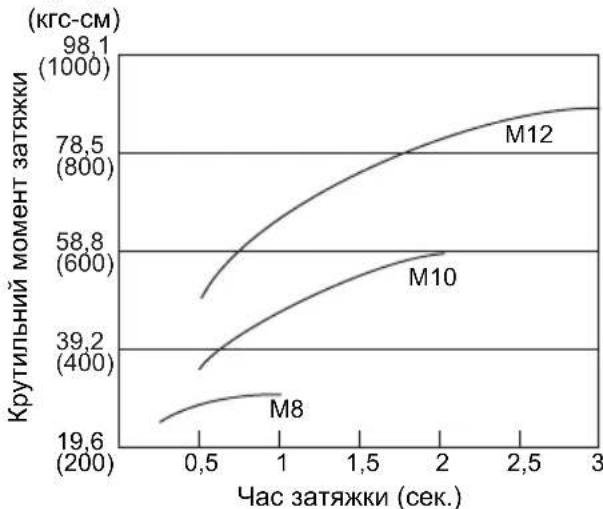
M8,M10,M12×25MMBucokoeJactuHn6oHT H·M
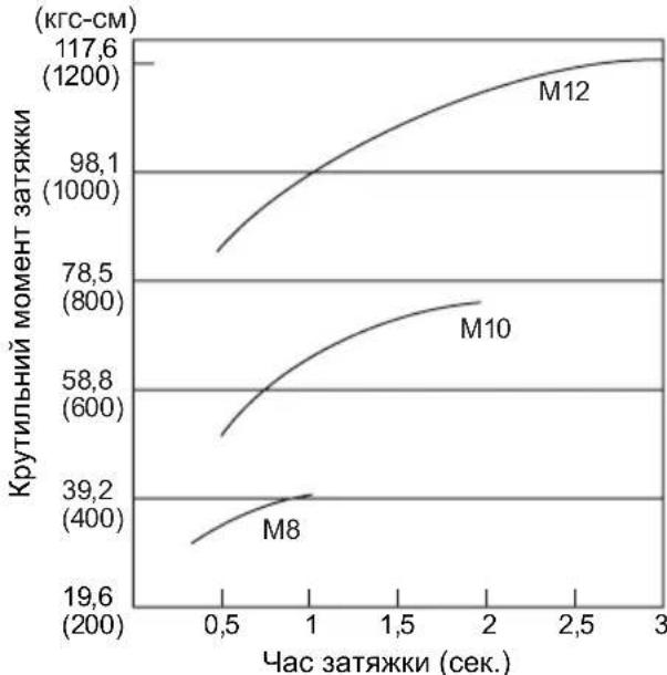
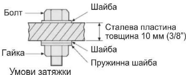
BukopncToByoTbcHacTynHi 60ntn.
CTaHdaptHi 60ntn: TnMIuHocTi 6,8
BucokoeJactNHyn Tn12,9
IPOsHHeHHa DO TnNy MiHocTi 6.8 Meka Tekyocti BoTa (80% Mexi MiHocTi Ha po3pNB) 48 Krc/MM² (68000 FyHT/KB. IIOIM) Meka MiHocTi Ha po3pNB 60% KrcfM (85000 FyHT/KB. IIOIM)
2) Yac 3aTAAKU
BilbI TpINBaIIH Yac npN3BOIDtB Do 3poCTaHH KpyTnIBHO MOMeHTy 3aTJKKN.
HaMipHa 3aTgKa, OHaK, He noiInuYc kOcTi i ckOpoye cTpOK ekCnnyatauHCTpyMeHTy.
3) Pi3hi diameTpns 6oJTa
Po3mip diAmetpy 6oJTa BnInBae Ha KpyTunbHIM MOMENT 3aTAAKKN.
Ja npabuno, 3i 36ilbweHHm diamepy 6oTata 3pocTaKpyTNbHIM MOMeHT 3aTAAKN.
4) yMOBn 3aTAAKKN
KpyTbHn MOMENT 3aTJxKn 6yNe BiDpi3HrTncn HABITdIg 6oNTiB OHaKOBOrO KNaCy,IOBXHH I) KOeepiciEHTy KpyTbHOrO MOMHTy (NoCTiHn KoeepiciEHT, IO Bka3yETbcR BnPo6HnKOM Ha npOdykii).
KpyTbHm MOMeHT 3aTJkN 6yDe BiDiP3HrTnC HABiTb DnA 6oNTiB 3 Ondoro MaTepiany (Ha npKnaI, ctaJI), B 3aJeXHOCTi BiD DOBODKn NOBepxHi.
KpyTnIbHm MOMENT 3HaUHO 3HNJyETbcra, kso 6oNT i raKa nouHaOTb o6ePtaTncpa30M.
5) 3a3op B natapoHi
KpytnbHm MOMENT 3HNKyEeTbcra, kUO dna 3aTAAKKN 6oNTa BnKOpNCTOBcYeTbcra NaTPOH WeCTurpaHHoI cOpMn HeiDNOiDHoro po3Mipy.
6) Bumkaay (nepeMkaay peryIIOBaHHa 3MiHHOI WbNIOKCTi)
KpytnbHm MOMENT 3HNKyEcBcRA, kUO npictpi BnKOpNCTOByEcTbcR 3 He NOBHicTIO HaxaTM BmNkauem.
OCHOBHNI IPIPNCPTPII
Matsushita Electric Works, Ltd.
Osaka, Japan