EY4542 - Saw PANASONIC - Free user manual and instructions
Find the device manual for free EY4542 PANASONIC in PDF.
| Product Type | Cordless Circular Saw |
| Brand | Panasonic |
| Model | EY4542 |
| Motor Voltage | 14.4 V DC |
| No-Load Speed | 3600 min⁻¹ (rpm) |
| Blade Diameter | 135 mm (5-3/8") |
| Blade Arbor | 20 mm (25/32") |
| Maximum Cutting Depth | 0 - 46 mm (0" - 1-13/16") |
| Total Length | 329 mm (12-61/64") |
| Weight (with battery EY9L40/EY9L41) | 2.65 kg (5.7 lbs) |
| Battery Type | Rechargeable Li-ion |
| Compatible Battery Capacities | EY9L40 (3 Ah) / EY9L41 (3.3 Ah) |
| Charger | EY0L80 |
| Cut Materials | Wood, non-hardened ferrous metals, non-ferrous metals, plastic |
| Recommended Blade Types | Carbide for metal (EY9PM13C), wood (EY9PW13A), plastic (EY9PP13B) |
| Dust Collection | Integrated dust box + vacuum adapter (EY9X012E) |
| Lighting | Integrated LED light |
| Protections | Automatic lower blade guard, blade brake, overheat and over-discharge protection |
| Maintenance | Clean with a dry cloth; have repairs done at an authorized center |
| Warranty | See included warranty card |
Frequently Asked Questions - EY4542 PANASONIC
User questions about EY4542 PANASONIC
0 question about this device. Answer the ones you know or ask your own.
Ask a new question about this device
Download the instructions for your Saw in PDF format for free! Find your manual EY4542 - PANASONIC and take your electronic device back in hand. On this page are published all the documents necessary for the use of your device. EY4542 by PANASONIC.
USER MANUAL EY4542 PANASONIC
Before operating this unit, please read these instructions completely and save this manual for future use.
English: Page 6 Dansk: Side 109
Deutsch:Seite 24 Svenska:Sidan 126
Français: Page 41 Norsk: Side 143
Italiano: Pagina 58 Suomi: Sivu 160
YkpaHcbKa: CtopiHa 193
This tool is a Multi Purpose Cutter. By changing the blade, it can be used to cut wood, metal, and plastic. Dust can be collected by an integrated dust case or via a connected vacuum (by attaching the hose to the tool).
DANGER
This product is a cutting tool, designed to cut through metal and wood. It has a rotating blade which is capable of cutting you deeply, causing serious injury or death. As a result, please read this manual and the cautionary markings on the tool carefully, and obey all of the Safety Instructions to avoid such injury.
WARNING
To avoid injury, never insert your finger or any other object into any opening of the tool.
WARNING
Read all safety warnings and all instructions.
Failure to follow the warnings and instructions may result in electric shock, fire and/or serious injury.
How to Use This Manual
- Please read this manual completely before starting to cut with your tool. If you let someone else use the tool, make sure they either read this manual or are fully instructed in the proper use and all safety precautions concerning the tool.
- Please keep this manual for future reference. It contains important safety information that you must follow to use the tool safely.
- This manual and product use the following signal words:
NOTE
Notes provide additional information that you should know about the tool.
CAUTION
Caution indicates a potentially hazardous situation, which could result in minor or moderate injury if not avoided. Cautions also alert you to unsafe practices to be avoided.
WARNING
Warning indicates a potentially hazardous situation, which could result in serious injury or death if not avoided.
DANGER
Danger indicates an imminent hazard which will result in serious injury or death if not avoided.
Read "the Safety Instructions" booklet and the following before using.
II. ADDITIONAL SAFETY RULES
Safety instructions for all saws
DANGER
1) Keep hands away from cutting area and the blade. Keep your second hand on auxiliary handle, or motor housing. If both hands are holding the saw, they cannot be cut by the blade.
2)Do not reach underneath the workpiece. The guard cannot protect you from the blade below the workpiece.
3) Adjust the cutting depth to the thickness of the workpiece. Less than a full tooth of the blade teeth should be visible below the work-piece.
4) Never hold piece being cut in your hands or across your leg. Secure the workpiece to a stable platform. It is important to support the work properly to minimize body exposure, blade binding, or loss of control.
5) Hold power tool by insulated gripping surfaces when performing an operation where the cutting tool may contact hidden wiring or its own cord. Contact with a "live" wire will also make exposed metal parts of the power tool "live" and shock the operator.
6) When ripping always use a rip fence or straight edge guide. This improves the accuracy of cut and reduces the chance of blade binding.
7) Always use blades with correct size and shape (diamond versus round) of harbour holes. Blades that do not match the mounting hardware of the saw will run eccentrically, causing loss of control.
8)Never use damaged or incorrect blade washers or bolt. The blade washers and bolt were specially designed for your saw for optimum performance and safety of operation.
Further safety instructions for all saws
Causes and operator prevention of kickback:
- kickback is a sudden reaction to a pinched, bound or misaligned saw blade, causing an uncontrolled saw to lift up and out of the work-piece toward the operator;
- when the blade is pinched or bound tightly by the kerf closing down, the blade stalls and the motor reaction drives the unit rapidly back to-ward the operator;
- if the blade becomes twisted or misaligned in the cut, the teeth at the back edge of the blade can dig into the top surface of the wood causing the blade to climb out of the kerf and jump back toward the operator.
Kickback is the result of saw misuse and/or incorrect operating procedures or conditions and can be avoided by taking proper precautions as given below.
1) Maintain a firm grip with both hands on the saw and position your arms to resist kick-back forces. Position your body to either side of the blade, but not in line with the blade.
Kickback could cause the saw to jump backwards, but kickback forces can be controlled by the operator, if proper precautions are taken.
2) When blade is binding, or when interrupt - ing a cut for any reason, release the trigger and hold the saw motionless in the material until the blade comes to a complete stop. Never attempt to remove the saw from the work or pull the saw backward while the blade is in motion or kickback may occur.
Investigate and take corrective actions to eliminate the cause of blade binding.
3) When restarting a saw in the workpiece, center the saw blade in the kerf and check that saw teeth are not engaged into the material.
If saw blade is binding, it may walk up or kickback from the workpiece as the saw is restarted.
4) Support large panels to minimize the risk of blade pinching and kickback.
Large panels tend to sag under their own weight. Supports must be placed under the panel on both sides, near the line of cut and near the edge of the panel.
5) Do not use dull or damaged blades.
Unsharpened or improperly set blades pro
duce narrow kerf causing excessive friction, blade binding and kickback.
6) Blade depth and bevel adjusting locking levers must be tight and secure before making cut.
If blade adjustment shifts while cutting, it may cause binding and kickback.
7) Use extra caution when making a "plunge cut" into existing walls or other blind areas.
The protruding blade may cut objects that can cause kickback.
Safety instructions for this saw
1) Check lower guard for proper closing before each use. Do not operate the saw if lower guard does not move freely and close instantly. Never clamp or tie the lower guard into the open position.
If saw is accidentally dropped, lower guard may be bent. Raise the lower guard with the retracting handle and make sure it moves freely and does not touch the blade or any other part, in all angles and depths of cut.
2) Check the operation of the lower guard spring. If the guard and the spring are not operating properly, they must be serviced before use.
Lower guard may operate sluggishly due to damaged parts, gummy deposits, or a buildup of debris.
3) Lower guard should be retracted manual - ly only for special cuts such as "plunge cuts" and "compound cuts." Raise lower guard by retracting handle and as soon as blade enters the material, the lower guard must be released.
For all other sawing, the lower guard should operate automatically.
4) Always observe that the lower guard is covering the blade before placing saw down on bench or floor.
An unprotected, coasting blade will cause the saw to walk backwards, cutting whatever is in its path. Be aware of the time it takes for the blade to stop after switch is released.
5) Do not use any abrasive wheels.
6) Wear a dust mask, if the work causes dust.
7) Use saw blades recommended by Manufacture.
8) Wear ear protectors when using the tool for extended periods.
9) The risk of kickback increases as the battery pack discharges.
10) Be sure to inspect material. Avoid cutting other different material.
11) Be careful not to drop the tool.
12) Never swing the tool.
13) Never cover the ventilation slots, and keep them free from dust or other material.
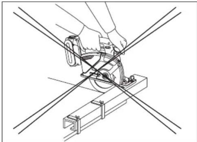
14) Do not clamp the tool in a vise. Never cut with the tool held upside down in a vise. This is extremely dangerous and can lead to serious accidents.
15) Never wear knitted gloves.
16) Be sure no one is below when using the tool in high locations.
17) Do not touch the blade immediately after operation. It may be hot and could burn your skin.
18) Do not touch material after it has been cut. Cut material may be very hot.
19) Do not use cutting oil. This use of cutting oil may cause a fire.
20) Do not cut workpieces covered or stained with gas, oil, solvents, thinners, etc.
Exposure to these materials may damage the transparent guard.
21) Do not remove the transparent and lower guards. If the transparent and lower guards is damaged or missing, return tool to authorized service center for replacement.
22) Do not start the blade when in contact with workpiece. Wait for blade to reach full speed before beginning cut.
Symbol
| Symbol | Meaning |
| V | Volts |
| Direct current | |
| n0 | No load speed |
| ... min-1 | Revolutions or reciprocations |
| A | Amperes |
WARNING
- Do not use other than the Panasonic battery packs that are designed for use with this rechargeable tool.
- Do not dispose of the battery pack in a fire, or expose it to excessive heat.
- Do not drive the likes of nails into the battery pack, subject it to shocks, dismantle it, or attempt to modify it.
- Do not allow metal objects to touch the battery pack terminals.
- Do not carry or store the battery pack in the same container as nails or similar metal objects.
- Do not charge the battery pack in a high-temperature location, such as next to a fire or in direct sunlight. Otherwise, the battery may overheat, catch fire, or explode.
- Never use other than the dedicated charger to charge the battery pack. Otherwise, the battery may leak, overheat, or explode.
- After removing the battery pack from the tool or the charger, always reattach the pack cover. Otherwise, the battery contacts could be shorted, leading to a risk of fire.
III. ASSEMBLY
Attaching or Removing Battery Pack
CAUTION:
Before inserting battery pack, check that the power switch in the tool actuates properly and returns to the "OFF" position when released.
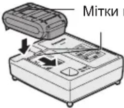
- To connect the battery pack (See Fig. 2)
Line up the alignment marks and attach the battery pack.
- Slide the battery pack until it locks into position.
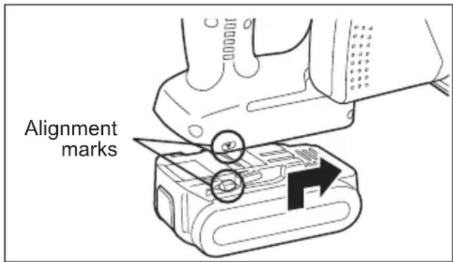
Fig. 2
- To remove the battery pack (See Fig. 3) Push on the button from the front to release the battery pack.
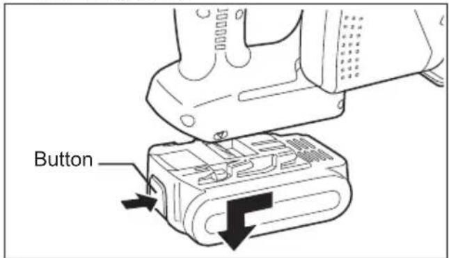
Fig. 3
IV. OPERATION Before Using the Tool
This tool is intended to cut unhardened ferrous metal, nonferrous metal, wood, and plastic. Refer to the "Accessories" section for a list of blades to be used for the proper applications of this tool. The following precautions must be followed to reduce the risk of injury;
- Do not cut stacked materials. Cut one piece at a time.
- Do not cut hardened steel.
- Cut materials with the wider edge of the shoe over the clamped side of the material.
- Do not touch the saw blade, workpiece, or cutting chips with bare hands immediately after cutting; they may be hot and could burn skin.
Each time you use the tool, you must make sure it is in good operating condition.
Use the following checklist:
- Is the blade installed in the correct direction? The arrow on the blade must point in the same direction as the arrow on the upper blade cover.
- Is the blade installed properly?
Make sure the hex bolt is tightened securely. (See Fig. 6) - Does the blade look alright? Replace the blade immediately if there are any cracks in it or if any teeth are broken.
- Does the lower guard close properly?
WARNING
To avoid injury, do not use the tool if the lower guard does not close quickly over the blade.
-
Is the transparent guard securely installed?
-
Is the battery pack charged and inserted firmly to the tool?
- Is the depth adjustment nut for cutting securely tightened?
- Is the workpiece securely clamped on a saw horse or bench?
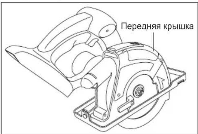
- Is the dust case or front cover clogged with dust?
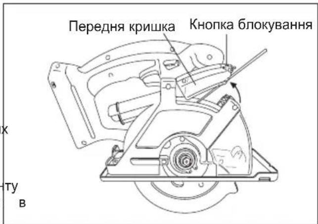
Disengage the front cover lock button and remove any dust that has become clogged inside the cover. If the cover is clogged, use a long object such as a manual screwdriver to unclog it. After doing so, close the front cover. (See Fig. 4)

Fig. 4
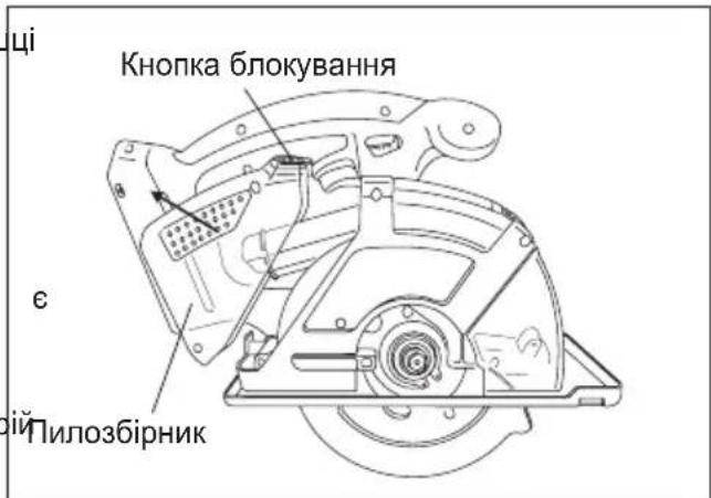
If there is dust inside the dust case, disengage the dust case lock button, detach the dust case, and remove the dust. After doing so, reattach the dust case. (See Fig. 5)
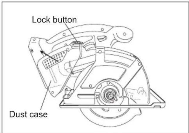
Fig. 5
Installing Blade
Follow these steps:
- Remove the battery pack from the tool.
- Remove any cutting debris from blade area.
- Use the retracting handle to retract (open) the lower guard.
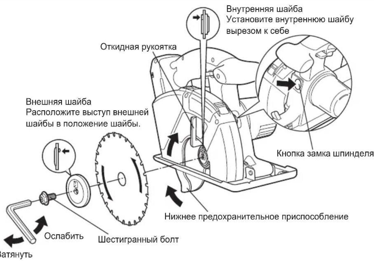
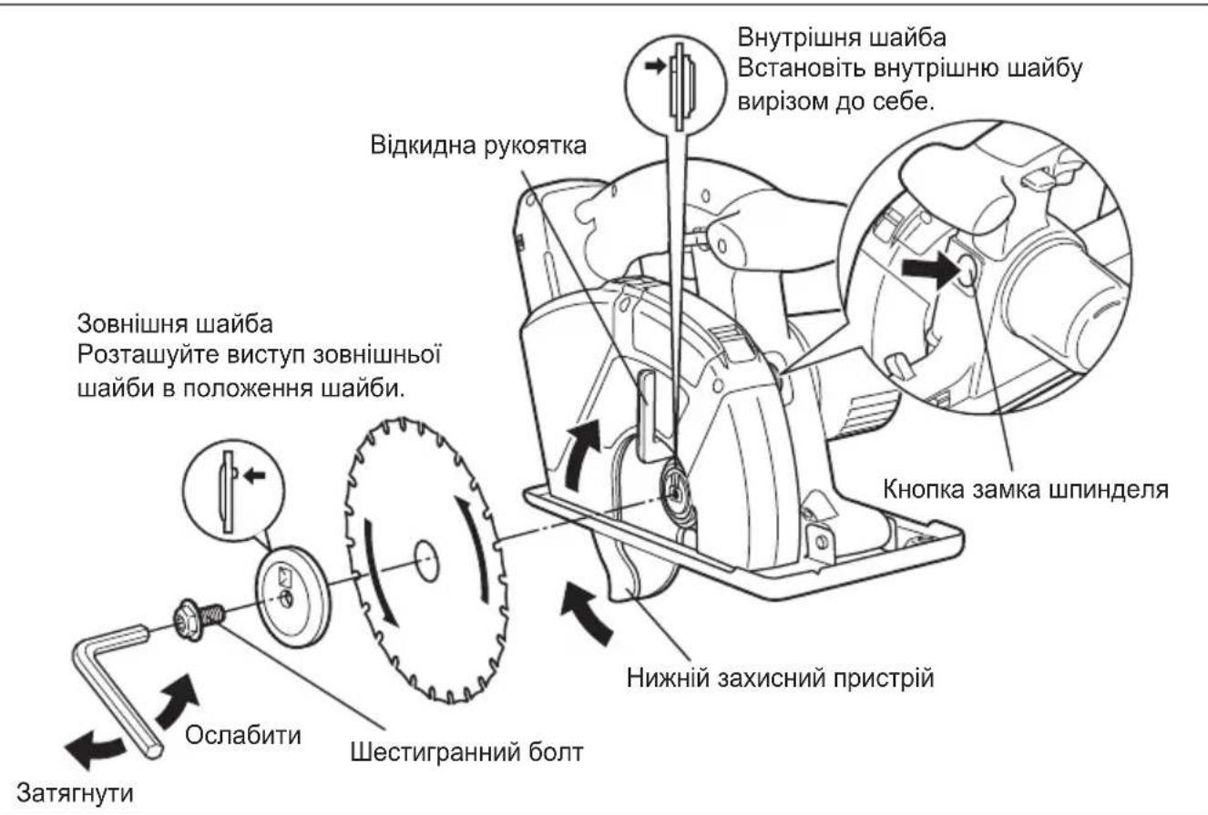
- Install the blade as illustrated. (See Fig. 6)
Make sure that both the direction arrow on the blade and the direction arrow on the transparent guard point in the same direction. - Set the outer washer in place.
- Insert the hex bolt.
- Hold the spindle lock button down. This prevents the blade from rotating.
- Tighten the hex bolt securely with the provided hex wrench. Store the hex wrench.
NOTE:
Keep the hex wrench in the storage slot on the tool's body when not using it.
WARNING
Failure to follow these instructions can result in serious personal injury.
Removing Blade
CAUTION:
The blade will be hot right after cutting. Be sure to let the blade cool down before removing it.
Follow these steps:
- Remove the battery pack from the tool.
- Hold the spindle lock button down. This prevents the blade from rotating.
- Use the provided hex wrench to loosen the hex bolt.
NOTE:
Keep the hex wrench in the storage slot on the tool's body when not using it.
- Remove the hex bolt and outer washer.
- Use the retracting handle to retract (open) the lower guard.
- Carefully remove the blade.
- Clean the tool if necessary.
CAUTION:
Be careful to avoid cutting your hands on the blade.
- When disposing of a blade, secure it inside heavy or corrugated paper. This will help prevent anyone from being cut by the discarded blade.
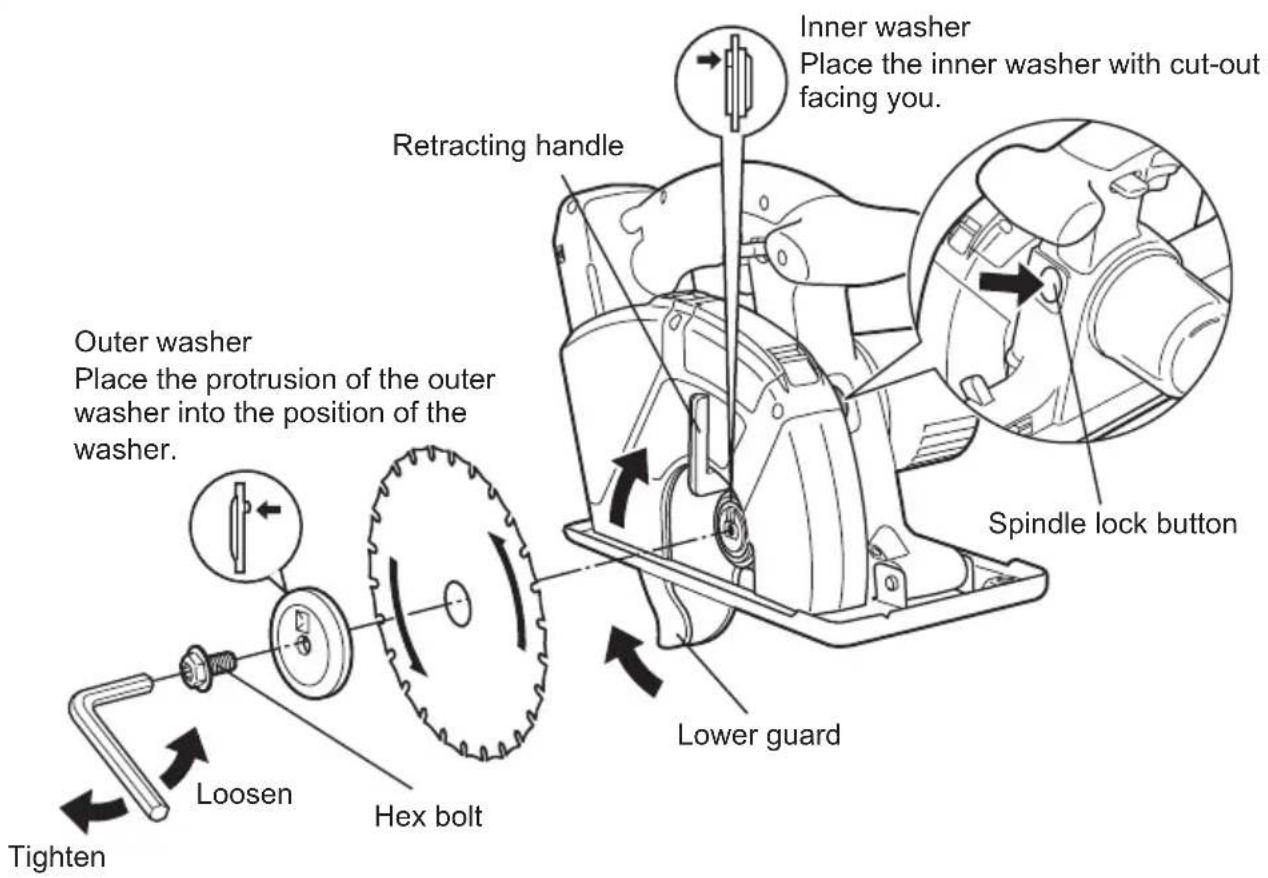
Fig. 6
Using the Tool
CAUTION:
To reduce the risk of injury read the Safety Instructions at the front of this manual before using the tool.
△WARNING
To reduce the risk of injury, wear safety goggles or glasses with side shields while using the tool. Additionally, wear a dust mask when cutting materials that generate excessive particulate matter. Do not use tool in the rain. Doing so may result in electric shock or cause the tool to emit smoke.
Do not cut materials on which there is any paint thinner, gasoline, oil, or similar build-up. Doing so may cause the dust case to crack, resulting in injury.
Follow these steps:
Hold the tool with both hands. (See Fig. 8) Do not attempt to remove cut material when blade is moving.
- Line up the sight line on shoe with your cut - ting line. (See Fig. 7)
Alignment with cutting line
- Position the notch on the shoe over the cutting line, aligning the top and bottom corners of the diamond-shaped opening with the line. As the cutting position may differ depending on the blade, do a trial cut beforehand.
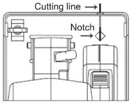
Fig. 7
- Press the switch lock lever down, then squeeze the power switch to start the motor, and then release the switch lock lever.
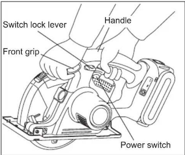
Fig. 8
CAUTION:
- Check that the switch lock lever works. If power switch can be activated without depressing the switch lock lever, discontinue use immediately. Take the tool to an authorized service center.
Always hold the handle with one hand and the front grip with the other. (See Fig. 8) Maintain a firm grip and depress the switch fully. - The blade should not touch the cutting material before you start the motor. Wait until the blade reaches full speed before starting a cut.
- This tool has no provision to lock the power switch in the "ON" position, and you must not attempt to secure it in the "ON" position.
- Start cutting when the blade reaches full speed.
- During cutting, keep your cutting line straight. Move the tool forward at a steady speed, while looking at the tip of the blade through the transparent guard.
WARNING
- To prevent dangerous kickback, keep the shoe of the tool flat on the surface of the material being cut.
-
Never force the tool. Use light and continuous pressure.
-
If the motor become too warm, stop cutting. Let the tool cool down before continuing work.
- It is always a safe practice to remove the battery pack after use and before storing the tool.
Cutting depth adjustment
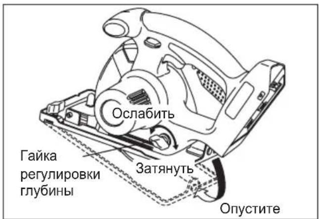
- Remove battery pack.
- Loosen the depth adjustment nut and adjust the cutting depth, using the graduations on the lower guard to gauge the depth. Once finished adjusting the depth, tighten the depth adjustment nut securely.
- When wood material is 10 mm (3/8") or less thick, adjust the cutting depth so that the blade protrudes approx. 5 mm (3/16") from the bottom of the material.
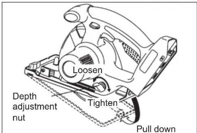
Fig. 9
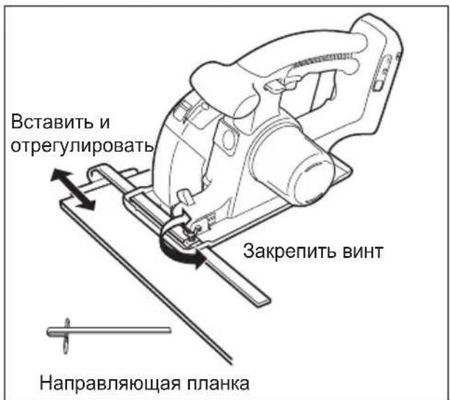
Rip fence (EY3500B7727)
(Available as an accessory, not included) Rip fence is convenient for rip cuts and repeated cuts of uniform width.
- Remove battery pack.
- Insert rip fence and adjust cutting width. (See Fig. 10)
- Fasten screw securely to fix rip fence.
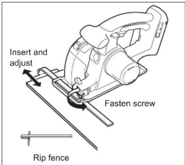
Fig. 10
Collecting Dust
WARNING
- Before cutting metal materials, always empty the dust case, open the front cover and remove the dust.
- Use the tool with the flammable materials in the dust case to cut metal materials may result in fire
- When cutting metal materials, always use the tool with the dust case attached.
- Flying sparks and metal chips may cause injury.
- When cutting metal materials, do not attach a vacuum cleaner.
Sparks and hot metal chips may cause the vacuum to be caught in fire. Operate the vacuum cleaner in accordance with its instructions.
(1) Collect dust in the dust case.
- Empty the dust case when it is filled up with dust.
- Empty the dust case before storing the tool.
-
Dust case capacity
-
When cutting electrical conduit with a diameter of 25mm (1"), approximately 130 cuts
- When cutting 45 ~mm (1 - 25 / 32^ ) × 45 ~mm (1 - 25 / 32^ ) lumber, approximately 150 cuts
NOTE:
Some materials may cause dust to become clogged inside the front cover when cutting those materials.
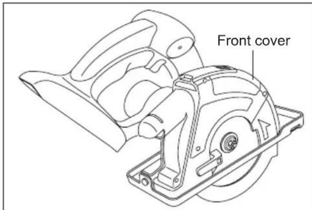
Fig. 11
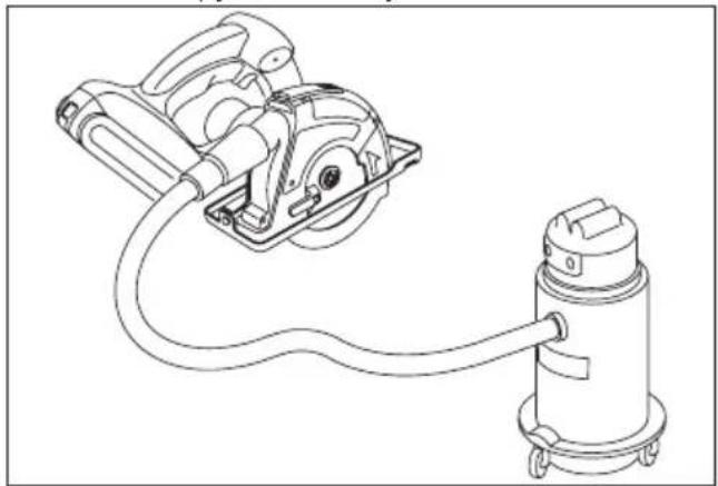
(2) Use with vacuum cleaner to collect dust.
- Connect the tool to the hose using the EY9X012E vacuum cleaner hose adapter (sold separately).
Compatible hose inner diameter: 25 mm (1") to 38 mm (1-2/1") - Operate the vacuum cleaner obeying its instructions.
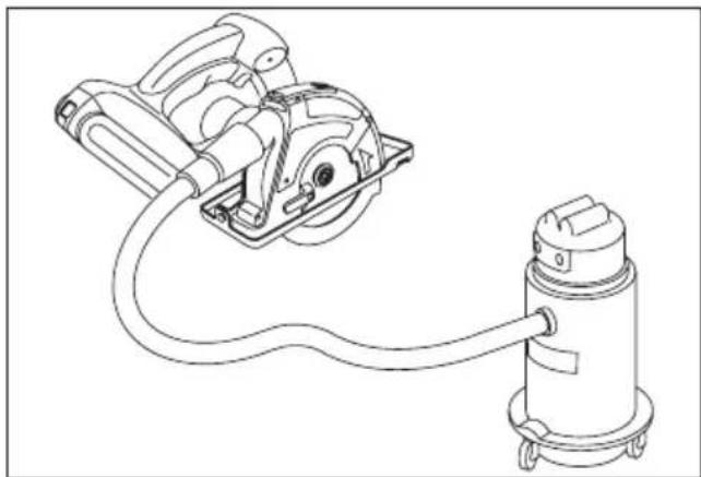
Fig. 12
NOTE:
When the tool has difficulty in ejecting or collecting dust, the dust outlet may be clogged with dust. Open the front cover and remove any dust.
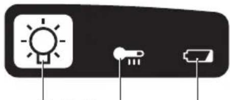
Control Panel
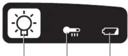
(1) (2) (3)
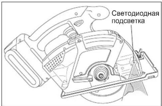
(1)LED light
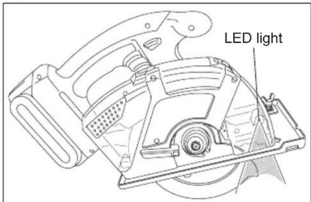
Fig. 13
Before the use of LED light, always pull the power switch once.
Press the LED light on button.
The light illuminates with very low current, and it does not adversely affect the performance of the tool during use or its battery capacity.
CAUTION:
- The built-in LED light is designed to illuminate the small work area temporarily.
- Do not use it as a substitute for a regular flashlight, since it does not have enough brightness.
- LED light turns off when the tool has not been used for 5 minutes.
Caution: DO NOT STARE INTO BEAM.
Use of controls or adjustments or performance of procedures other than those specified herein may result in hazardous radiation exposure.
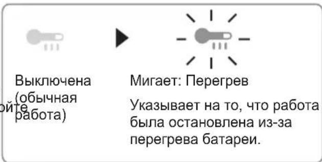
(2) Overheat warning lamp
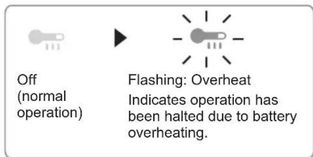
The overheating protection feature halts tool operation to protect the battery pack in the event of overheating. The overheat warning lamp on the control panel flashes when this feature is active.
- If the overheating protection feature activates, allow the tool to cool thoroughly (at least 30 minutes). The tool is ready for use when the overheat warning lamp goes out.
- Avoid using the tool in a way that causes the overheating protection feature to activate repeatedly.
(3) Battery low warning lamp
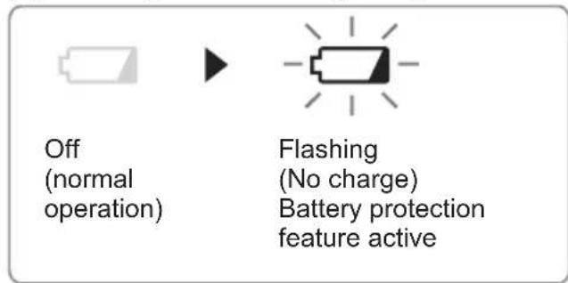
Excessive (complete) discharging of lithium ion batteries shortens their service life dramatically. The tool includes a battery protection feature designed to prevent excessive discharging of the battery pack.
The battery protection feature activates immediately before the battery loses its charge, causing the battery low warning lamp to flash.
If you notice the battery low warning lamp flashing, charge the battery pack immediately.
For Proper Use (Further Detail)
WARNING
To prevent the risk of serious personal injury:
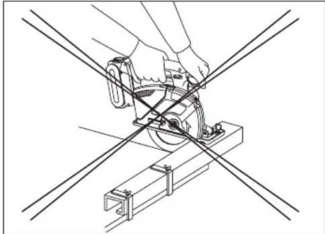
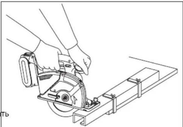
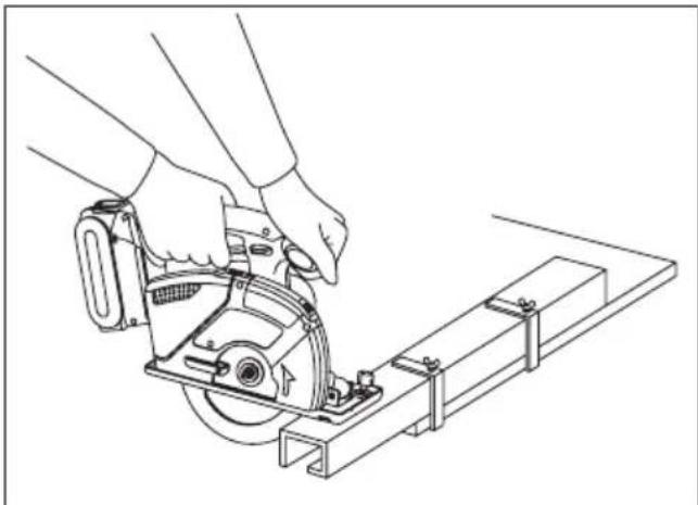
It is important to use an appropriate device to hold the material being cut properly, and to hold the tool firmly with both hands to prevent loss of control which could cause personal injury.
Figure 14 shows proper cutting position.
Note that hands are kept away from cutting area.
- Make sure bystanders are away from work area and from underneath of workpiece.
- When cutting, do not try to hold the material with your hand.
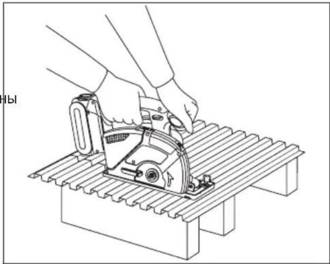
Cutting large sheets;
Support large sheets. Be sure to set the depth of the cut so that you only cut through the workpiece, not through the supports. (See Fig. 15)
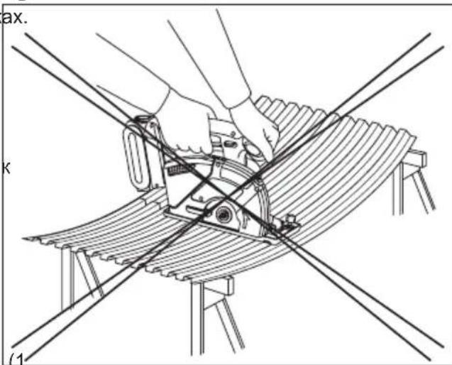
Large sheets sag or bend if they are not correctly supported. If you attempt to cut without levelling and properly supporting the workpiece, the blade will tend to bind, causing kickback. (See Fig. 16)
- Don't support the material away from the cut.
Cutting thin or corrugated materials;
Cut thin and corrugated materials at least 25 mm (1") from the edge of the workpiece to avoid injury or damage to the tool caused by thin strips of metal being pulled into the upper guard.
- Use sharp blades only. Clean and sharp blades minimize stalling and kickback.
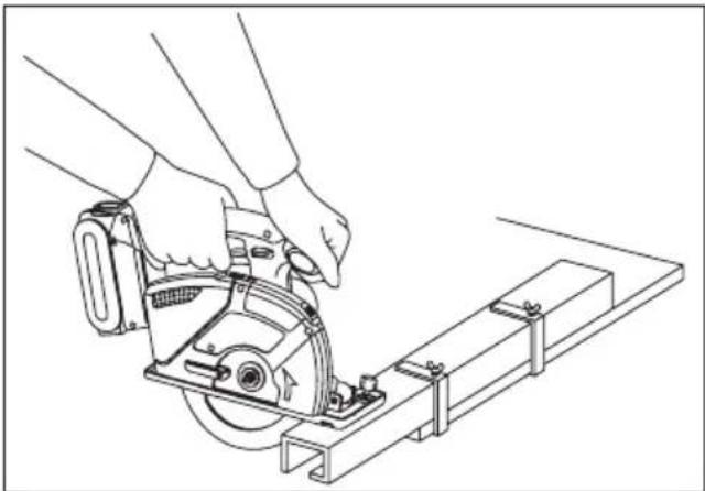
Fig. 14
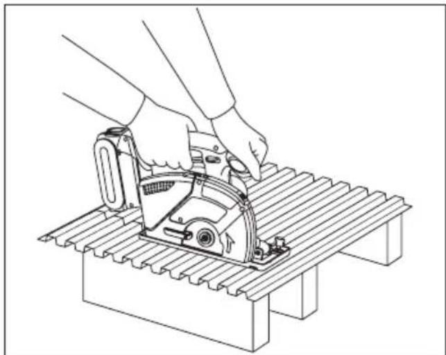
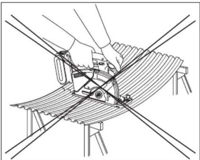
Fig. 15
Fig. 16
WARNING
To prevent the risk of serious personal injury:
- When making an incomplete cut or cutting is interrupted, or blade is binding or tool is stalling; release the power switch immediately and hold the tool motionless in the material until the blade comes to a complete stop.
- To avoid kickback, never attempt to remove the tool from the work or pull the tool backward while the blade is in motion. Make sure the blade has come to a complete stop, then remove tool from cut.
-
To resume cutting, start tool, allow the blade to reach full speed, reenter the cut slowly and resume cutting.
-
Place the wider part of the shoe on the part of the work piece which is solidly supported (See Fig. 17), never on the section that will fall off when the cut is made. (See Fig. 18)
Hold the tool firmly to prevent loss of control. Working carelessly can cause severe personal injury.
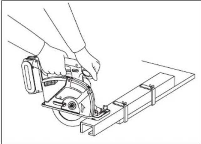
Fig. 17 Fig. 18
- Make sure the blade stops.
Even though your tool has a brake, before setting the tool down, make sure the blade has come to a complete stop and the lower guard has closed.
- Do not use if anything seem unusual. Remove battery pack immediately.
If the tool body becomes very hot, or does not work properly, remove the battery pack and do not use. Have it checked by an authorized service center.
WARNING
To prevent the risk of serious personal injury or fire, do not try to repair the tool by yourself. Never disassemble or modify the tool body. There are no user-repairable parts inside.
- NEVER ALLOW THE TOOL TO COME IN CONTACT WITH YOUR BODY.
After completing a cut, do not allow the tool to brush against your leg or side.
Since the lower guard is retractable, it could catch on your clothing and expose the blade. Keep clothing away from tool. Be aware of the exposed blade sections that exist in both the upper and lower guard areas.
△WARNING
Because cutting metal creates sparks;
Always use safety goggles.
- Do not use tool near any flammable substance or in an area where flammable substances are used. Fire and burn injury could result.
- Never engage the spindle lock while blade is running, or engage in an effort to stop the tool. Never turn the switch on when the spindle lock is engaged. Serious damage to your tool will result.
[Battery Pack]
For Appropriate Use of Battery Pack
Li-ion Battery Pack (EY9L40/ EY9L41)
- For optimum battery life, store the Li-ion battery pack following use without charging it.
- When charging the battery pack, confirm that the terminals on the battery charger are free of foreign substances such as dust and water etc. Clean the terminals before charging the battery pack if any foreign substances are found on the terminals.
The life of the battery pack terminals may be affected by foreign substances such as dust and water etc. during operation.
- When battery pack is not in use, keep it away from other metal objects like: paper clips, coins, keys, nails, screws, or other small metal objects that can make a connection from one terminal to another.
Shorting the battery terminals together may cause sparks, burns or a fire.
- When operating the battery pack, make sure the work place is well ventilated.
- When the battery pack is removed from the main body of the tool, replace the battery pack cover immediately in order to prevent dust or dirt from contaminating the battery terminals and causing a short circuit.
Battery Pack Life
The rechargeable batteries have a limited life. If the operation time becomes extremely short after recharging, replace the battery pack with a new one.
Battery Recycling
ATTENTION:
For environmental protection and recycling of materials, be sure that it is disposed of at an officially assigned location, if there is one in your country.
[Battery Charger]
Charging
Cautions for the Li-ion Battery Pack
- If the temperature of the battery pack falls approximately below -10^ ( 14^ ), charging will automatically stop to prevent degradation of the battery.
Common Cautions for the Li-ion/Ni-MH/Ni-Cd Battery Pack
The ambient temperature range is between 0^ (32^) and 40^ (104^) .
If the battery pack is used when the battery temperature is below 0^ (32°F), the tool may fail to function properly.
- When charging a cool battery pack (below 0^ (32^) ) in a warm place, leave the battery pack at the place and wait for more than one hour to warm up the battery to the level of the ambient temperature.
- Cool down the charger when charging more than two battery packs consecutively.
- Do not insert your fingers into contact hole, when holding charger or any other occasions.
CAUTION:
To prevent the risk of fire or damage to the battery charger.
- Do not use power source from an engine generator.
- Do not cover vent holes on the charger and the battery pack.
- Unplug the charger when not in use.
Li-ion Battery Pack
NOTE:
Your battery pack is not fully charged at the time of purchase. Be sure to charge the battery before use.
Battery charger (EY0L80)
- Plug the charger into the AC outlet.
NOTE:
Sparks may be produced when the plug is inserted into the AC power supply, but this is not a problem in terms of safety.
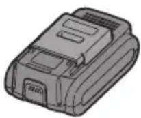
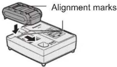
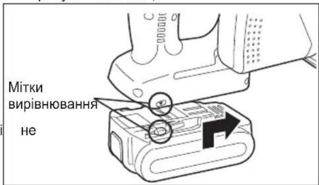
- Insert the battery pack firmly into the charger.
1 Line up the alignment marks and place the battery onto the dock on the charger.
2 Slide forward in the direction of the arrow.
-
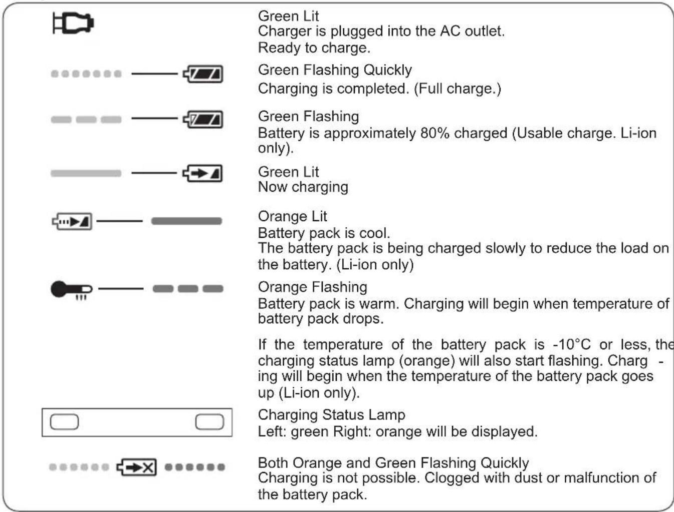
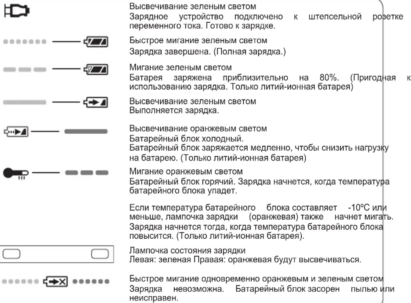
During charging, the charging lamp will be lit. When charging is completed, an internal electronic switch will automatically be triggered to prevent overcharging.
-
Charging will not start if the battery pack is warm (for example, immediately after heavy-duty operation).
The orange standby lamp will be flashing until the battery cools down.
Charging will then begin automatically.
- The charge lamp (green) will flash slowly once the battery is approximately 80% charged.
- When charging is completed, the charging lamp will start flashing quickly in green color.
- If the temperature of the battery pack is 0^ or less, charging takes longer to fully charge the battery pack than the standard charging time.
Even when the battery is fully charged, it will have approximately 50% of the power of a fully charged battery at normal operating temperature.
- If the power lamp does not light immediately - ly after the charger is plugged in, or if after the standard charging time the charging lamp does not flash quickly in green, consult an authorized dealer.
- If a fully charged battery pack is inserted into the charger again, the charging lamp lights up. After several minutes, the charging lamp may flash quickly to indicate the charging is completed.
Ni-MH/Ni-Cd Battery Pack
NOTE:
When you charge the battery pack for the first time, or after prolonged storage, charge it for about 24 hours to bring the battery up to full capacity.
Battery charger (EY0L80)
- Plug the charger into the AC outlet.
NOTE:
Sparks may be produced when the plug is inserted into the AC power supply, but this is not a problem in terms of safety.
- Insert the battery pack firmly into the charger.

-
During charging, the charging lamp will be lit. When charging is completed, an internal electronic switch will automatically be triggered to prevent overcharging.
-
Charging will not start if the battery pack is warm (for example, immediately after heavy-duty operation).
The orange standby lamp will be flashing until the battery cools down. Charging will then begin automatically.
- When charging is completed, the charging lamp will start flashing quickly in green color.
- If the charging lamp does not light immediately after the charger is plugged in, or if after the standard charging time the charging lamp does not flash quickly in green, consult an authorized dealer.
- If a fully charged battery pack is inserted into the charger again, the charging lamp lights up. After several minutes, the charging lamp may flash quickly to indicate the charging is completed.
Lamp Indications
Information for Users on Collection and Disposal of Old Equipment and used Batteries

These symbols on the products, packaging, and/or accompanying documents mean that used electrical and electronic products and batteries should not be mixed with general household waste.
For proper treatment, recovery and recycling of old products and used batteries, please take them to applicable collection points, in accordance with your national legislation and the Directives 2002/96/EC and 2006/66/EC.
By disposing of these products and batteries correctly, you will help to save valuable resources and prevent any potential negative effects on human health and the environment which could otherwise arise from inappropriate waste handling.
For more information about collection and recycling of old products and batteries, please contact your local municipality, your waste disposal service or the point of sale where you purchased the items.
Penalties may be applicable for incorrect disposal of this waste, in accordance with national legislation.
For business users in the European Union
If you wish to discard electrical and electronic equipment, please contact your dealer or supplier for further information.
[Information on Disposal in other Countries outside the European Union]
These symbols are only valid in the European Union. If you wish to discard these items, please contact your local authorities or dealer and ask for the correct method of disposal.
Note for the battery symbol (bottom two symbol examples):
This symbol might be used in combination with a chemical symbol. In this case it complies with the requirement set by the Directive for the chemical involved.
V. MAINTENANCE
WARNING
To avoid severe personal injury, always remove the battery pack from the tool before starting any maintenance procedure.
CAUTION:
To assure product SAFETY and RELIABILITY, servicing should be performed by an authorized service center. Always insist on genuine Panasonic replacement parts.
Cleaning Tool
Keep your tool clean for good cutting performance, and to help keep it safe to use.
Follow these steps:
- Remove the battery pack from the tool.
- Wipe the tool with a dry, soft cloth. Do not use a wet cloth or cleaning liquids.
They could damage the tool's finish.
- Be sure to rub off any oil or grease which could make the tool slippery or hard to handle.
- Remove the blade and brush off any dust.
CAUTION:
To avoid injury or damage to the unit, never immerse any part of the tool in a liquid.
Transparent Guard
WARNING
If the guard is cracked, or is broken, take the tool to an authorized service center for replacement.
Do not attempt to operate tool. It could result in serious personal injury.
Never use your tool with a damaged transparent
guard or without the transparent guard installed
Flying chips could result in serious injury.
VI. ACCESSORIES
WARNING
- The use of any accessories not specified in this manual may result in fire, electric shock, or personal injury. Use recommended accessories only.
- Use of a blade on material that is thicker or thinner than that recommended for that blade will result in a rough cut, and could increase the risk of "kickback" or other injury.
Carbide-tipped Blade for Metal
- EY9PM13C
For cutting unhardened ferrous material
Thickness of material
0.5 mm - 6.0 mm (1/32" - 1/4")
Carbide-tipped Blade for Thin Metal (Optional accessory)
- EY9PM13D
For cutting unhardened thin ferrous thin material that clean cutting edge required
Thickness of material
0.5mm - 6.0mm (1 / 32^ - 1 / 4^ )
Carbide-tipped Blade for Wood (Optional accessory)
- EY9PW13A
For cutting wood in general
Carbide-tipped Blade for Thin Wood (Optional accessory)
- EY9PW13B
For cutting thin wood that clean cutting edge required
Recommended thickness of material up to 12 mm
Carbide-tipped Blade for Plastic (Optional accessory)
- EY9PP13B
For cutting plastic
Recommended thickness of material acrylic and vinyl chloride plates:
2.0 mm - 5.0 mm (5/64" - 3/16")
corrugated pates, pipes
0.8 mm - 5.0 mm (1/32" - 3/16")
Vacuum hose adaptor (Optional accessory)
- EY9X012E
Rip Fence (Optional accessory)
- EY3500B7727
For convenience of rip cuts and repeated cut of uniform width
VII. SPECIFICATIONS
| Motor voltage 14.4 V DC | |
| Blade speed 3600 min | -1 (rpm) |
| Blade size Outside diameter 135 mm (5-3/8") Arbor size 20 mm (25/32") | |
| Maximum cutting depth 0 – 46 mm (0" – 1- | 13/16") (φ135 mm blade) |
| Overall length 329 mm (12-61/64") | |
| Weight (with battery pack: EY9L40/EY9L41) | 2.65 kg (5.7 lbs) |
| Noise Vibration | See the included sheet. |
BATTERY PACK
| Model EY9L40 EY9L41 | ||
| Storage battery Li-ion Battery | ||
| Battery voltage 14.4 V DC (3.6 V × 4 cells) | ||
| Capacity | 3 Ah | 3.3 Ah |
BATTERY CHARGER
| Model | EY0L80 |
| Rating | See the rating plate on the bottom of the charger. |
| Weight 0.95 kg (2.1 lbs) |
[Li-ion battery pack]
| Charging time | 3 Ah | 14.4 V | 21.6 V | 28.8 V |
| EY9L40 | EY9L60 | EY9L80 | ||
| Usable: 35 min. | Usable: 45 min. | Usable: 55 min. | ||
| Full: 50 min. | Full: 60 min. | Full: 70 min. |
| Charging time | 3.3 Ah | 14.4 V | ||
| EY9L41 | ||||
| Usable: 45 min. | ||||
| Full: 60 min. |
[Ni-Cd/Ni-MH battery pack]
| Charging time | 7.2 V | 9.6 V 12 | V 15.6 V 18 | V 24 V | |||
| 1.2 Ah | EY9065 | EY9080 | EY9001 | ||||
| EY9066 | EY9086 | ||||||
| 20 min. | |||||||
| 1.7 Ah | EY9180 | EY9101 | |||||
| EY9182 | EY9103 | ||||||
| 25 min. | |||||||
| 2 Ah | EY9168 E | Y9188 | EY9106 | EY9136 | EY9116 | ||
| EY9107 | EY9117 | ||||||
| 30 min. | 60 min. | ||||||
| 3 Ah | EY9200 | EY9230 | EY9210 | ||||
| 45 min. | 90 min. | ||||||
| 3.5 Ah | EY9201 | EY9231 | EY9251 | ||||
| 55 min. | 65 min. | ||||||
NOTE: This chart may include models that are not available in your area.
Please refer to the latest general catalogue.
NOTE: For the dealer name and address, please see the included warranty card.
ONLY FOR U.K.
VIIIELECTRICAL PLUG INFORMATION
FOR YOUR SAFETY PLEASE READ THE FOLLOWING TEXT CAREFULLY
This appliance is supplied with a moulded three pin mains plug for your safety and convenience.
A 3 amp fuse is fitted in this plug.
Should the fuse need to be replaced please ensure that the replacement fuse has a rating of 3 amp and that it is approved by ASTA or BSI to BS1362.
Check for the ASTA mark or the BSI mark on the body of the fuse.
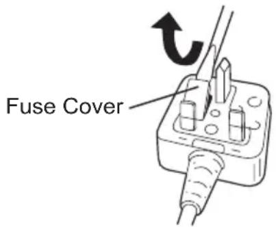
If the plug contains a removable fuse cover you must ensure that it is refitted when the fuse is replaced.
If you lose the fuse cover the plug must not be used until a replacement cover is obtained.
A replacement fuse cover can be purchased from your local Panasonic Dealer.
IF THE FITTED MOULDED PLUG IS UNSUITABLE FOR THE SOCKET OUTLET IN YOUR HOME THEN THE FUSE SHOULD BE REMOVED AND THE PLUG CUT OFF AND DISPOSED OF SAFELY.
THERE IS A DANGER OF SEVERE ELECTRICAL SHOCK IF THE CUT OFF PLUG IS INSERTED INTO ANY 13 AMP SOCKET.
If a new plug is to be fitted please observe the wiring code as shown below.
If in any doubt please consult a electrician.
IMPORTANT:
The wires in this mains lead are coloured in accordance with the following code:
Blue: Neutral
Brown:Live
As the colours of the wire in the mains lead of this appliance may not correspond with the coloured markings identifying the terminals in your plug, proceed as follows.
The wire which is coloured BLUE must be connected to the terminal in the plug which is marked with the letter N or coloured BLACK.
The wire which is coloured BROWN must be connected to the terminal in the plug which is marked with the letter L or coloured RED.
Under no circumstances should either of these wires be connected to the earth terminal of the three pin plug, marked with the letter E or the Earth Symbol 1一
How to replace the fuse: Open the fuse compartment with a screwdriver and replace the fuse and fuse cover if it is removable.
This apparatus was produced to BS800.
qualified
I. EINLEITUNG
0,5 mm - 6,0 mm (1/32"-1/4")
0,5 mm - 6,0 mm (1/32"-1/4")
2,0 mm - 5,0 mm (5/64" - 3/16")
Wellplatten, Rohre
0,8 mm - 5,0 mm (1/32" - 3/16")
2,0 mm - 5,0 mm (5/64" - 3/16")
Pacco battery Li-ion
NOTA:
2,0 mm - 5,0 mm (5/64" - 3/16")
lastre, tubi ondulati
0,8 mm - 5,0 mm (1/32" - 3/16")
[Pacco battery Li-ion]
| Tempo di caricamento | 3 Ah | 14,4 V 21,6 V 28,8 V | ||
| EY9L40 | EY9L60 | EY9L80 | ||
| Utilizzabile: 35 min. | Utilizzabile: 45 min. | Utilizzabile: 55 min. | ||
| Completa: 50 min. | Completa: 60 min. | Completa: 70 min. | ||
| Tempo di caricamento | 3,3 Ah | 14,4 V | ||
| EY9L41 | ||||
| Utilizzabile: 45 min. | ||||
| Completa: 60 min. |
[Pacco battery Ni-MH/Ni-Cd]
| Tempo di caricamento | 7,2 V | 9,6 V 12 | V 15,6 V 18 | V 24 V | |||
| 1,2 Ah | EY9065 | EY9080 | EY9001 | ||||
| EY9066 | EY9086 | ||||||
| 20 min. | |||||||
| 1,7 Ah | EY9180 | EY9101 | |||||
| EY9182 | EY9103 | ||||||
| 25 min. | |||||||
| 2 Ah | EY9168 EY9188 | EY9106 | EY9136 | EY9116 | |||
| EY9107 | EY9117 | ||||||
| 30 min. | EY9108 | 60 min. | |||||
| 3 Ah | EY9200 | EY9230 | EY9210 | EY9210 | |||
| 45 min. | 90 min. | ||||||
| 3,5 Ah | EY9201 | EY9231 | EY9251 | EY9251 | |||
| 55 min. | 65 min. | ||||||
2,0 mm - 5,0 mm (5/64" - 3/16")
No裱 up with the ingredients.
No裱 up with the ingredients.
No裱 up with the ingredients.
No裱 up with the ingredients.
Forma de utiliser este manual
2,0 mm - 5,0 mm (5/64" - 3/16")
2,0 mm - 5,0 mm (5/64" - 3/16")
2,0 mm - 5,0 mm (5/64" - 3/16")
Rekommenderad materialtjocklek for korrugerade plattor eller ror:
0,8 mm - 5,0 mm (1/32" - 3/16")
Slangadapterfordammsugare(valfritttillbehör)
- EY9X012E
Mothall (valfritt tillbehör)
·EY3500B7727
2,0 mm - 5,0 mm (5/64" - 3/16")
bølgeplater, rør
0,8 mm - 5,0 mm (1/32" - 3/16")
Kobling for stovsugerslange (tilleggsutstyr)
- EY9X012E
Kloygjerde (tilleggstyr) - EY3500B7727
2,0 mm - 5,0 mm (5/64" - 3/16")
aaltolevyt, putket
0,8 mm - 5,0 mm (1/32" - 3/16")
Otdaaya yBJIeTcpe3yJbTaTom HnpaBnIbHOn 3KcNpyataunnn nJIbln HApUWeHn TExHnKn
BbINOJIHHeHnpa6OTnnTexHnueCKOcoCToHnIe MoXHO n36ExKaTb, PpINHMaHaJLeXaUne MepbI IpeDIOCTOPOXHOCTN, KOToPbI pInBeDeHbI HNXe.
1) Kpenko ydepxnbAte nny o6eHmny pykamn B TAKOM NIOXKeHH, KOtOpoe NO3BOJNTnpOTNBODeIcTBoBaTb cIaAM OTdauH. BCTaHbTe TaK, YTO6bl Bawe TeNo haxOAnNoCb C KaKoJ-Nn60 H3 CTOpOH OTHOCHTbHO NOnOTHa Nnbl, Ho He Ha ODHON JINHN C NOnOTHom.
OTdaua MoKeT cTaTb npuHoi CkaKa nnBIB
obpaTHOM HAnpaBHeHn, HO OepaTop DoJxHe H
noTepeTb cnoc6HoCTb ynpaBHeHn BCJeDcTBnE
CNI OTdaHn, ecn OH 6ydt PrnHMaTb
HaIneKaune MepbI npeOcTOPOXHOCTN.
2)ПиИСКРИВЛЕн ИОЛТHA,ИИnpпперьIBaHn ПpoUeCCA pe3aHЯ NO KaKoI-NI6O npuHHe,OTnyCTte NyCKaTeJIb U ydepxNBAHTe NIIy HEnOДВIXHOB MaTePnaJIe Do TEX NOP, nOKa NOLOTHO NOLHOCTbO He OCTaHOBNTcR. HNKOrda He nbITaHTecb BblHyTB NIIy I3 DeTaNn IIN NotaHTb NIIy B O6paTHOM HAnpaBJIeHN BTO BpeM, KOrDa NOLOTHO HaxODITcR B DBHXJEHH, INaYe MoXeT NocJeDObaTb OTdauA. BbIByTE npuHHy IckpIBJIeHЯ IN ppeIprIMITE HeO6xOДMbIe DeIcTBnI DnI yCTpaHEHЯ IIJIb npuHbI NCKPUBJIeHЯ.
3)При NOВTOPHOM 3anycke DBURAteJIЯ, KOrda
нолOTHO ПИльи HaxODNTcB HByTpN IprOIIa
obpa6aTbIBaEMoI DeTJIH, BbyIpOBHЯIe
nOLOTHO B npONIIe N npOBepbTe, He
3actPJIIN 3y6bIpyNIbI B MaTePNaIe.
EcnI NOJOTHO ПИльи NCKpNBITcR, OTdaua MoKet
NoJeCTBOBaTb Ha obpa6aTbIBaEmyIO DeTaNb B
JIIO6OM HAnpaBHeHIn Prn IOBTOPHOM 3anycke
DBURAteJIЯ nIJbl.
4) Hadejxho noidepKnBaIte 6oJIbIe TOHKe Iockn dIg TORO, YTO6bl CBeCTN K MmHMMy pIck 3aUeMJIeHn NOJOTHa N OTdauN.
Bolbne TOHKe IOCKN IMeOT TEHNCHIO KIOBnCAHIO NOI CBOIM CO6CTBeHHbIM BECOM.
NoepKNaOuNe ONOpbl Heo6XoDIMO
pacnoJoxntb NOI DOCKO C O6eHX CTOPOH, PdOM
c LInHne pa3pe3a n OKOLO Kpa JDOCKN.
5) He nClojb3yTe TynbIe nn NobpeKdEHHbIe noJIoTHa.
He3aToueHHbIe HINHe npabnBHOyCTaHOBJIeHHbIE NOIOTHa CnyKAT npuHNO y3KOrO npOnnA, YTO npBEdT K Upe3MepHomy TpeHIO, NCKpNBJeHHIO NOIOTHa I OTdauYe.
6) PbIyArn 6IOKuPoBKn rIy6HbI nHaKNoHa NOIOTHa DOJXHbI 6bITb TOHOb BbICTaBJeHbI n HaJExHO 3aΦHKcnpoBaHbI nepeD hauaON pe3aHn.
Ecn npncnoc6neneHna yctahOBKn noIOxehnnoIOTHa CdbHyTCB BO BpeMa pe3AHN, 3TOMOKETcTaTb npuHOn HCKpNBHeHn nOTdauH.
7)Ппмnte ДОПНHTeHbHbIe МерblnpedocTopoxHoctn npn BbINOJIeHnN“Bpe3aHnN”Byxke cyuecTBYIOUcne cTeHbI nIIN dpyrHe HeoctynHbIe DJIaOCMOTpa yuaCTKn. BbICTyanaIOUee BnpeD noIoTHO MOKeT haHaTb pe3aHnE npdMeTOB, KOTOpbIe cTaHyT npuHHOI OTdaH.
Hnctpykunno6e3onacchoCTn DnnaHHoNnIbl
1)пөрд haayanom 3крлуаци кждь pa3 npobepaHTe npabnIbHocTb 3akpbITna HxKHeRo npedoxpaHTeIbHoro npncnoc6JIeHn. He 3крлуatnpuyte nny, ecn HxKHee npedoxpaHTeIbHOe npncnoc6JIeHne He 6ydet cBo6OdNo DBuRaTbcr N HeMeJTeHNO 3akpbIBaTbcra. HNKOrda He 3akpenJaTe HxKHee npedoxpaHTeIbHOe npncnoc6JIeHne B OTKpbITOM NOLOXKeHn Pn NOMOOn 3axNMOB nn XOMYTOB. B cnyae naDEHn RAHHee npedoxpaHTeIbHOe npncnoc6JIeHne MOKe T nOHyTbcra. NodHMITE HxKHee npedoxpaHTeIbHOe npncnoc6JIeHne C NOMOuBu OTKnIDHOpyKoTkn N y6eDInTEcb, YTO npn NIObIx yrrnx rny6Hne pe3aHnO OHO CBO6OdHo nepemeuaeTcR n KacaetcnoTHa NNbl NIN KAKO-NINO DeTaTI.
2)ПровьтefункционpoBaHne npyxHBi HxKHero npedoxpaHTeIbHOro npncnoC6JIeHn. Ecnn npedoxpaHTeIbHoe npncnoc6JIeHn He npyXHa He 6ydtФyHKUONHOPOBaT HaIeXaUM O6pa3OM, INx HxJxHO OTPMOHTuPoBAr NpeD 3KcNlyaTaun. HxKHee npedoxpaHTeIbHOe npncnoc6JIeHn MOKeT FyHKUONHOPOBaT HeIOCTaTOUHO 6bICTpo BCJeCTBn IOBpeXdEHNr DeTaNe, HAKONJIeHn INIKNX OTLOKeHn, INI IOnaDaHn O6JOMKOB.
3) HnXHHe npEdoxpaHntbHoe npncnoc6JeHne HxHOb OTKnDbIBaT BpyHyTOIbKO npn BbIOJNHeHH CneuJaBbIX npOnJIOB, TaKnx KaK "Bpe3aHne" n "CNOxHbI npOnJ. POnHMnTe HxHHe npEdoxpaHntbHoe npncnoc6JeHne c NOMOsbIO OTKnIDHO pyKoTkn I ONyCTNe erO, KaT OToBKO NOJOTHO NJIbBOINDET BMATEpHaI. DnA BCex OCTaJIbHbIX BnIOB NN, HxHHe npEdoxpaHntbHoe npncnoc6JeHne DOJXHO FyHKUOHPOBaTB ABTOMATUYeCKN.
4) He 3a6ydbTe npOBepntb, yTo HnXHee 2
npedoxpaHnteIbHoe npncnocobHeHne
3akpbIbAet nOToTHo, nepeT TeM, KaK
noJoxHTb NlNy Ha Bepctak NnHa NoJ.
He3aunuHoe, DnKyuueecr no INhepunn
noJIoTHo cTaHET npuHHoToro, yTO nNla npi
DbHXKeHN B o6paTHOM HappaBHeHn 6yJeT
pe3aTb BCE, yTO nonaTeCra Ha nyTu. NOMHInTe, yTO DJIg OCTaHOBKn NOJIOtha IocJe BbIKIIOUeHnH Heo6xOIMo HEKOToPoE Bpemr.
5) He nCnoNb3yIe HnKaKnx ⅢnΦoBaJIbHbIX DnCKOB.
6) OdeBaIte npOTnBONbIeByIO macky, ecn pe3aHne DeTaN cOnpOBoXdaeTcra 06pa3OBaHHem nbII.
7) Исторы пеловашипогибдддддддддддддддддддддддддддддддддддддддддддддддддддддддддддддддддддддддддддддддддддддддддддддддддддд徴.
8) OdeBaIe HayuHnKn npn nCNoJIb3OBaHHn HnCTpyMeHTa B TeueHne dIITeJIbHoro nepHOda BpeMeHN.
9) Pnck OTdau nOBbiuaetc npn pa3pndke 6atapeHoro 6Ioka.
10) BHHMaTeIbHo 6cneDyIte MaTePnaI.
36eRaIte pe3aHnI dpyrnx MaTePnaIob.
11) Bydte octopoxhbl, YTo6bI He ypoHHTb HcTpyMeH.
12) Hn B Koem cnyuae He noDBeuBaIte nHcTpymeHT.
13) HnKOrda He 6Iokpyte BeHTnIaHNoHHbIe OTBepCTnI n CoepXnTe nx CBO6oHbIMN OT nbIIN dpynx MaTePnaIOB.
14) He 3axnmaTe nHCTpyMeHT B TnCKax. Hn B KOem Cnyae He BbINOJHnTe pe3aHne, 3axaB NHCTpyMeHT B nepeBepHyTOM NOIOXeHN B TnCKax. 3To ype3BbIyauHo OnaCHO mOxKet npNBecTu K cepbe3HbIM HeCchaTHe bIM CnyaM.
15) HnKoIa He oJeBaIe TpNkOtaxHbIe pyKaBnCbI.
16)Пи ИСПОЛБЗОВАнн Ha BbICOTe, y6eДNTecb, YTO BHN3y HNKOrO HeT.
17) He npikacaiTecb K noIOnHy cpa3y nocJe 3KcNlyatauH. OHO MOKeT 6bITb rOpAum N o6keybawy kOxy.
18) He npikacaiTecb K MaTePnany nocne TORO, KaK OH 6bln pa3pe3aH. pa3pe3aHHbI MaTePnAI MoXeT 6blb OueHb rOpAUM.
19) He И сноьзуиTe 3MyЛьснOHhoe MacNo.
Takoe И сноьзOBaHne 3MyЛьснOHoro Macna
MOXKeT Bbl3BaTb NOxAp.
20) He npon3BOOnTe pe3aHn8 o6pa6aTbIbAemorO n3denn, c NOKpbITnem nn PnTHAmN 6eH3nHa, macna, pactBopnteJe, pa36abNTeJe n T.d. Bo3deInCTBne 3tNx MaTePnAnOB MoKeT noBpeDnTB npo3paHoe ppeOxpaHntelbHoe npncnoc6JenHe.
21) He chnmaTe npo3paHoe n HxHHee npedoxpaHTbHoe npncnoc6JeHn. Ecnn npo3paHoe nn HxHHee npedoxpaHTbHoe npncnoc6JeHne NOBpeXdeHO nn OTCyTCTByeT, BepHnte HNCTpyMeHT B yNoJHomOeHHbI CepBnCHbI ueHTp dJa 3aMeHbl.
22) He BKJIOHuaIte HNCTpyMeHT,ecJIN IOJIOTHO KacaetcO6pa6aTbIBaEMoRO H3JeJIH. IIOJOKdTe,IOKA POJIOTHo HE JOCTnHET IIOJHO CKOpocTH,IpexKe Yem HaUNHaTb pe3aHHe.
23) B COOTBETCTBHH C ΦeepaJIbHbIM 3aKOHOM Pocnn "O 3aIHTe IpaB IOTpe6nteJe", cpoK Clyk6bl IJRA DAHHOR O3JeINPABeH 7 roam, 1200 3apAikam (TOJIbKO IJRA 6aTaapeHoro 6Ioka) C dAtbI IPOHN3BOIDCTBa IIpyUCIOBH, qTO H3dJIne HcIOJIb3yETCBA CTporom COOTBETCTBHH C HACTOUIE INHCT pyKIIe IIO EK CIIy aTaIHN IIpIMHeHMbIMN TexHHueCKHMn CTAHApTAMn. IIHaHACOHNK 3JIeKTPNK BOpK Co., JIT.
CIMBOJIbI
BydTe octopokhbl, yTo6bI He nope3aTb Baun pyKn nOJOTHOM.
Bb6paCbBAI NOIOTHO,3aBepHnTe ero B IIOHTHyU ININ roPpnpOBaHHyO 6yMAY. 3TO NOMOXET PpeoTbPaTb Iope3bl Koro-Jn60 Bbl6poeHHbIM IIOITHom.
C
Pereynipobka rny6nbl pe3aHna
CHIMMTe 6aTapeHbI 6JOK.
Ocna6bTe raKy perynipOBKn rny6nHbI n otperynpyte rny6nHy pe3aHnC nOMoCbIO DeleHn, HaHeceHHbIX dIy n3MepeHn rny6nHb HA HxKHee npdoxpaHntelbHoe npncno6JIeHne Pocne 3aBepSeHnpeRynipOBKn rny6nHbI npOHO 3aTAHTE raKy perynipOBKn rny6nHbl.
* Ecni TOniHa DpeBecnHb CoCTaBnIe 10 MM (3/8 IIOMa) NII MEnbIe, OtperyNpyTe rny6Hpe3AHNA TaKIM o6pa3OM, YTO6bl NOnOTHO BbICTynano np6bn3ntelbHo Ha 5 MM (3/16 IIOMa) C HIXHe CTOpOHb MaTePnAna.
Pnc.9
Hapablaioa nnahy3500B772
(BnEeTc npHaJnEeKHOCTbIO, He BKnIOueHa B KOMnNEKT)
HanpaBnaIooaI nnAHa yO6Ha IJIpe3aHnnpope3eNIOBTOPOUoEoCpe3aHnOOnHaKOBOnuPInbI.
- CHIMITE 6aTapeHbI 6JOK.
BctabbTe hnpabnnoyio nnaHky n Otperynpyte rny6nHy pe3aHn. (Cm.Pnc.10)
HaJExKHO 3aTAHNTe BnHT, 3TO6bl 3aФИКСИРОВАТБ HAnpaBJIHOUyU ПlaHKy.
Pnc. 10
C6op nbln
OCTOPOXHO
*Bcerda ouHuaTe nbIeSc6OpHnK nepepe3aHnEM MeTAna, oTKpoIte nepeDHeepedeOxpaHntelbHoe npncnocobneHne uYdAnTe nbIb.
IcnoB3OBAHne pe3aka c orHeonacbIMMaTePnAJaMn B nbIe6OpHnke dIpe3aHnMeTaNMA MOKeT npVBecT N BO3ROPaHnO.
-
PpH pe3aHm MeTaIIa BcerIa NcNoJIb3yIte JIe3ak C npNKpeHneHHbIM nbJIec6OpHkOM.
-
JIeTaeHne NCKpbI H MeTaJIINueeCKne CTpyKMOrY TnpuBecTN K NOJyHeHIO TpaBMbl.
-
He noDcoeHnHnTe nbIeCoc npn pe3aHm metanla.
NckpbI n ropnye MeaJIInueckne ctpyKMOrY T BbI3BaTb BO3rOpAHne Nblncocca.BoBpeMpa60tbc NblncocOM co6JHOaTe BCEHnCTpyKcH K Hemy.
(1) C6op nbln c nomoou bno nbIeSc6OpHnka.
- Ecnn nbIiec6opHnK 3aIOnHeN nbIbIO, OChCTnteero.
- Ouiana Te nbIe6opHnK nepeD xpaHeHem pe3aka.
-
EMKOCtB nbJIneC6OpHnKa
-
Pn pe3aHnn 3JIeKtpnueckoro Tpy6oNpOBOda DnaMeTpom 25 MM (1 HOM), np6IIN3NTeJbHO 130 npOnNoB
-Прп pe3aHH DepeBHHOrO 6pycka c pa3Mepam45 MM (1-25/32 Дюма) x 4 MM (1-25/32 Дюма), пиблнЗИтельно 150 прпинов
ПРИМЕЧАНЕ:
Ipnpe3aHnneKoTOpbix MaTePnaIOB nbIbMoXeT cKaanNBaTbcra Ha BHyTpEHHe NOBepxHOCTInpepeHne KpbuKn.
Pnc.11
(2)Использованne nbilencoca дя сбopa nbiln.
* PoiocoeHnHte pe3ak K WlAnHy C NOMOubc aanTepa EY9X012E dna WlAnhra nbInecoca (npoanaetc oTdeNbHo).
BHyTpEHHn DnAmEtP COBmecTUMOro ⅢJHaRa:OT25MM(1DIOIM)do38MM(1-2/1IIOIma)
- Bo Bpempa6oTbIC nbIeCocOM co6HouaTe BCE IHCTpyKuIN K HEmy.
Pnc. 12
ПРИМЕЧАНЕ:
Ecn npn n3BneueHn pe3aka nn c6ope nbInn BO3NkaOT TpydnoCTn. Bo3MOxHo, OTBepCTne Dn Bb6pOa nbInn 3a6nTo nbInbIO. OTKpo nepeDHIO KpbIuKU INoJIHOCTbU ydaJIITe nbInb.
Panaelb ynpaBleHnA
(1) (2) (3)
(1) CBeToIIOHaI IOcBETka
Pnc.13
Bcerda Haxmamte nepeknoateIb nntAHnOdH pa3 nepei nCnoIb3OBaHHe m CBeToNDHOHOcBETKn. HaxmTe KhONky BKNIOueHn BBKIOueHn CBeTONDHO NOcBETKn. IoDCBETKa rOpNT npn OChb HN3KOM Toke OKa3bIBaet He6laornpnTHoro BO3deJCTBnHa npOn3BOOnTeJIbHOCTb INHCTpyMeHTA BO BpEmpa60Tb IIN Ha EMKOCTb erO 6atapeH.
BHIMAHNE:
Bc TpoehHa CBeToNDnOHa Na DCB eTKa npedHa3NaYeHa Dn BpeMeHHoro OCBeUeHn He6oJbIoo pa6Oey 30Hbl.
He nCnoJb3yIte ee B KaueCTBe 3aMeHbI NOCTOHHORo oHaPka, TaK KaK OHa He OblaJaAeT DoCTaTOHOr npKOCTbIO.
- EcnnnHCTpyMeHT He nCnoNb3yETcB TeueHne 5 MNHyT, CBeToOnOHa Ha NoCDcBEtKa BbIKIIOuHTc.
BhimaHne:HE CMOTPetb HA JIyU.
IcnoJb3ObaHne opraHOy npaBHeHn nppeynpoBOK, IIO Bo BbIOJIHHeHne IpOeDyp INbIM o6pa30m, CEM yKa3aHO B DaHHo IHCTpyKuN, MOxET pINBeCTN KNONaDaHnIO NOB 03DeEChTBNe ONaCHOrO n3NyueHn.
(2)празурждаюшаяламночka neperpews
Функця 3auntbI OT neperpeBa ocTaHaBnBaet pa6oty INHCTpyMeHTa DnA 3aunTb6atapeHoro 6noKa B clyuae nepereBa.Bo Bpemra pa60tB 3toi cyHKzni Ha naneN ynpabneHn 6ydet MmraTb npdynpdntelbHa JAMNOka nepereBa.
B Cnyuae BKNIOUeHnФyHKUN 3aunTbI OT npeperpeBa DaIte INHCTpyMeHTY NONHOCTbIO OCTbITb (NO KpaHHeMpe, B TeueHne 30 MNHyT). INHCTpyMeHT 6yET rOTOB K pa6Ote, KOrda npedynpeDInTeNbHa JAmnoUka IORachET.
-136eata nCIOB3OBAHn HNCTpyMeTa BpeXIMe, npKOTOpOM qacto BKJIIOUaETcra yHKun 3aunTbI ot neperpeBa.
IcnoJIb3yIte TOnbKO OCTpbIE NOIOTHa. YnCTbIe N OCTpbIE NOIOTHa yMeHbIaHT 3aCtpeBaHne n OTDAuV.
Pnc. 14
Puc. 15
Pnc.16
OCTOPOXHO
IpypeDToBpaueHn npCKa cepbe3HO TpaBMbl:
- Ecnn pe3aHne He 6ydt 3akOHHeHO nn 6ydt npepBaHO, nn noTHO corHeTcra, nn pe3ak 3actprHer; HEmdJIeHHO OTnycTtpe nepeKIOuAteIb NITAHn ydePxAbaTe pe3ak HenoBHXHO B MaTePnaJe Do Tex nop, noka noJOTHO He OCTaHOBTcra NOHOCbIO.
- UTO6bI N36ExKATb OTdauH, HIKoJa He NbItaTecB BbHyTb pe3ak N3 O6pa6aTBaEMO rN3eHNr IIN NOYtpe3ak Ha3aD B To Bpem, KaN PNOTHO BpaAaETc. Y6eINTecb, YTO NIOHTHO NIOHOCTbIO OCTAHOBNIOCb, a 3aTEM ydaJIte pe3ak N3 pa3pe3a.
-
UTo6bI BO3o6HOBnTb pe3aHne, BKNIOHTpe3ak, daTe NOnOTHy nINbI Ha6paTb NOnHyO CKOpocTb, MeNHeHO BBeInTe erO B npONnI IN BO3o6HOBnTe pe3aHne.
-
IomeaTe 6oJee uHPOkyu OacTb OCHOBaHna Ha aactn o6pa6aTBiBaemoro n3denn, KOtOpoe npOho
3akpenHe (CM.Pnc.17), HNKOrda He nomeauTe Ha Ty aactb, KOTopra OTpndet, KOrda pa3pe3 6ydt cdeHa
(CM.Pnc.18)
Kpenko ydepkinaTe pe3ak, YTO6bl npedotBpATNTb notepIO KOHTpOJa. He6peXHa ra60ta MoKET npUBeCTn K
TjKeJeON TpaBMe.
Pnc.17 Pnc.18
- Y6eIITecb, yTO IIOJIOHO OCTaHOBNIOCb.
HecmotpnaTO, yTo daHHbI uHCTpyMeHT OCHaueH TOpMo3OM, npeD TeM, KaK noIOXHTb uHCTpyMeHT, y6eINTcE 7TO IONOTHO NINbI NOJHOCTbHO OCTaHOBUNOCb HnHXHe ppeOxpaHnteBHOe npncnoc6JeHne 3akpbIto.
- He nCnoJb3yIte uHCTpyMeHT, ecn yTO-JIN60 BByIJIaIIT Heo6bIuHO. HEmeJeHHo CHIMTe 6aTapeHbI 6JIOK.
Ecnn Kopnyc nHCTpyMeHa CnBHO HArpeBaetc nn HNCTpyMeHT He pa6oTaET HaIeXaumm 6pa30M, n3BneKeTe 6ataepnHb N He IcNoJb3ynte erO. O6patNTecb B cepBnchbl cHTp dIra erO npOBepKn.
OCTOPOXHO
UTo6bI npEdupeDntb pNCK cepbe3HO TpaBMBI INI NOXapa, He NbITaHTecb CAMOCToTeNbHO OTPeMOHTPOBaTb HnCTpymEt. Hn B KOem cnyae He pa36upaTe n BINOJ3MeHnTe KOpNc IHCTpymEtA. BHyTpHi Hero HeT qAcTei, npEduHaueHHbIX dIpypeMOHTa ONb3OBaTeNm.
- HNKOΓΑ HE ΠΟ3BOJIΛΥ έTE PE3AKY COπΡΚACATbÇ C BΑΙΜ TΕΝΟΜ.
Pocne okonuaHnpe3aHn, He nO3BOJnTe pe3aKy npKacatbcra K Baue Hore nIi Baewmy 6oky.
NockoBky HxHHee npedoxpaHnteIbHoe npncnocO6neHne ABJETcR OTKdbBaHOUMcR, OHO Mo3aueHtbcra 3a oDeKdy uOrnITb nolOTHO nnbl. Depxnte nHCTpyMeNT noJaIbwe ot odexdJI. He 3abBaHTe 06 oroneHHbIX yuctkax nONOTHa nnbl B paioHe kak BepxHrero, TaK n HxHrero npedoxpAHnter npncnocO6neHn.
OCTOPOXHO
Tak kak pe3aHne MeTaJIa cOnpoBOXJaTeCnCKpAM;
Bcerda oDeBaIte 3aunTHbIe ouKn.
He nCnoJb3yIte HnCTpyMeHT pAOM c KaKIMN-Jn6o OrHeONaChbIMn BeIeCTBaMn, INn B MeCTax, IDe NcNoJIb3yIOTcR orHeONaCHbIe MaTePnaJIbI. 3To MoKet npNBecTn K NoXapy n NOJyEHHIO OKOROB.
- Hn B Koem cnyae He haxmaite Ha 3amok uHHdJe BO BpeM dBHXeHn NOLOTHa NINbI Hne nbTaHTecb TAKIM CnoCobom OCTaHOBNTu INCTpyMeH. Hn B Koem clyae He BKIOuaTe nepeKIOUaTe 3aDeiCTBOBaHHOM 3AMKe uHHdJe. To npueDet K cepbe3Homy NobpeXdeHIO INCTpyMeHTa.
[BaTapeiHbIe 6nok]
- Ecπn 6batapeHbI 6bok He NcNoJIb3yeTcR, xpaHnte ero noaIbIe ot TaKnx MeTaJInuYeCKNX npEdMeTOB, KaK cKePkn, MoHeTbI, KlnOuN, rBO3dN, Wypynbl, INIpyrNX MeKnx MeTaJInuYeCKNX npEdMeTOB, KOToPbIe MOrY TnpNBecTn K KOHTaKTy OndHOJ KJIeMMbl C dpyqoi
XpaHeHne 6aTapeeHbIX 6JIOKOB BMeCTe MOxET CTaTB PnUHHO B03HNKHOBeHnI NCKP, OXKOrOB IINI NOXapa.
Bo Bpempa60bI c 6aTapeHbIM 6JOKOM y6eHTecb, YTO pa6ooye IOMeUeHne XopoWo npOBetpmbaETcra.
-ПиИЗВЛЕЧEN6БАТAPЕHORO6БLOKAИЗОCHOВНОКОРпуca ИНСТPyMeHTa, HeMeДЛЕHHO 3AmEHITeKpbIshky 6БАТAPЕHORO6БLOKAДЯп徳OTВрашЕнЯ3aRpy3HeHNY KJIEMM 6БАТAPENbIbIOИгяЗblIO,УTOMOKeT BbI3BaTb KOPOTKOE 3AmblKaHNe.
![PANASONIC EY4542 - [BaTapeiHbIe 6nok] - 1](/content/2026/03/454645/images/2325f8bc930e08561e62cebf3221d34b68bae354c2fe03412bd69a0c0713df63.jpg)
Cpok cnyk6bI 6aTapeHoro 6noka
AkkymyIaTOPhIe 6aTapeHmEOT orpaHnueHHbI cpoK cnJx6bl. Ecn nocne 3apJdkn BpeM qyHKuHOHPOBaHn CtaHOBUTcra Ype3MePHO KOpOTKmM, 3aMeHnTe 6aTapeHbI 6lOK Ha HOBbI.
YTNIN3aun 6atapen
BHIMAHHE:
B ueJx 3aunTbI OKpykaIOUeI Cpebl I yTuIN3aCIM MaTePnaJIOB, y6eINTEcB, YTO OHa yTuIN3nPoBaHAB OΦuNtAlbHO pPeHa3HaueHHom MeCTe, eCNI TaKOBbIeEcTB B BaWeI cTpaHe.
[3apяДhoe yctpoIcTBO] 3apяДka
Mepbl ppeoctopoxKHOCTN dIJI NTNeBO-NOHORO 6aTaapeHORO 6loka
- Ecnn TemnepaTpa 6batapeHoro 6Ioka onyctntc Hxke npn6n3ntelbHo -10°C (14°F), 3apraKa ABTOMATUeCKn Ppekpatntc Tn npdeoTbpaueHn yxudseHn XapaKTePncTnk 6batapei.
1056e MepbI IpeoctopoxHocTn 1JIa NHTN-NOHOrO/HNKeJIb-MeTaJI HOrpNDHO/HHKeJIb-KaDMneBOrO 6aTaapeHoro 6Ioka
Mnana3OH TemnepaTypbI OkpykaUoSeI cpebl coctabnaret O 0^ (32^) do 40^ (104^)
Ecn6baTapeHbI 6JOK 6yJeT NcNoJIb3OBaTbcr npn Tempeatype 6bTapeHnxKe 0^ (32^) HNCTpyMeHT MoKTe He cyHKUHOHropOBaTb NaIeKaUIM Opa3OM.
-При зарядк eхолоног 6ат apeиног 6лoka (c Tempepatypoи Hnke 0°C (32°F)) B Tepno MeCTe, octabte 6aTapeinbI 6JOK B 3Tom MeCTe I noDoxTe 6Oone Ondoro yaca, noka 6aTaper HarpeeTcra do ypoBna TempepatpybI OkpykaIouei Cpebl.
- OxlaIte 3apAHHoe yCTpoNCTBO npn nocneObATEbHOB 3apAKe 60one qem DByx 6aTapeHbIX 6nOKOB.
He BCTaBnIe Baun nanbUbi B KOHTaKTHbIe OTBePcTna, KOrDa Bby depXnTe 3apAnHoe ycTpoiCTBO, a TaKke B npynx cnuyax.
BHIMAHHE:
Ipy npdeOTbpaueHn pycka noxapa nnIOBpeKdEHHa 3apAHO yCTpoiCTBa.
He nCnoJb3yIte B KaueCTBe nCTOuHnKa nHTaHnReHepaTOp DnurTaTeN.
He 6IOKpyuTe BENTNUJUcIOHbIe OTBepCTnHa 3apyHOM yCTpOJcTBe n 6aTapeHOM 6IKe.
- BbiknIOHTe 3apJdHoe yctpoIcTBO n3 wTeNceJIbHO npo3ETKn, ecnn OHO He NCNOJb3yeTcra.
ЛNTи-ноHHь 6aTapeHbI 6JOK ПРИМЕЧАНЕ:
BaW 6aTapeHbI 6nok He YBnETCa NOHOCbIO 3apJxHeHHbIM BO Bpemn PokynK. He 3a6yDbTe 3apAnTb erOp nepeNcNoJb3OBAHnEM.
3apnHoe yctpoNCTBd(ey0L80)
- BknHouHTe 3apAHHoe yCTpoiCTBO B WTeNCEbHyIO pO3eTKy NepemEHHO TOKa.
C
CBeToBie HndPkatOpbl
HΦopMaζη no o6paζeHHo C OTXODaMn ДЯ CTpaH, He BXODaζx B EbponeiCKn Co103


IeNCTBnE 3Tnx CmBOJIOB paCnpocTpaHReTcra TOnbKO Ha Ebponeeckn Co103.
EcnBbco6npaetecb Bbl6pocntb daHHbIe 3nemeHTbl, y3HaTe B MeCThbx OpraHax BnaCTN NnY dInepa, KAK cneDyET NOCTynatb C OTXoamn TaKOrO Tnna.
V. OBCJIyXINBAHNE
OCTOPOXHO
TTo6bI n36eKaTb noJyehncrepe3hIX TpaBM, Bcerda n3BLeKaITe 6aTaepHbI 6lOK n3 HnCTpyMeHTa nepeHaayamIo6oBn pOceDypbl TEXHNueCKOrO 06cIyKuBaHnA.
BHIMAHNE:
Дя oe cneue Hn8 E3O I AC HADEXKHOCTU n3dEIny, 6cnyxuBaHnE DOJXHO BbINOJIHrTbcry yNOJHOMOeHHbIM CepBnCHbIM ueHTpom.Bcerda HacTaINBaIte Ha INCNoJIb3OBaHNOpunHaNbHbIX 3anachbIX qactrx fnpMbI Panasonic.
Очирka Иструм enta
IopdepknaBte HNCTpyMeHT B YnCTOTE dJr coXpaHEny XopoWe nCnoc6hocTn K pe3aHnIO V 6e3oNaChOCTn nCnoJIb3ObaHnY.
BbInoJIHnTe cNeDuIoune DeIcTBn:
- 3BNeKeIte 6aTapeHbIb 6NOK n3 HcTpymeHTa.
- BbITpIte INHCTpyMeHT cyXoI, MArKOI TkaHbIO. He NCIOJIb3yIe BnaJxHyIO TkaHb IIN OChUaIOUne KNDKOCTH.
OHN MOryT NOBpeDnTB NOKpbITne pe3aKa.
- 06aTeBHO ydaHnTe BcIO CMA3KU INN MaCNO, KOToOpoe MoKeT CdeNaTb INHCTpyMeHT CKOJIb3KIM INI TAgKeNbIM dIy UdepXaHnI.
- CHIMnTe NOJIOTHO N BbITpNTe nbJIb.
BHIMAHHE:
Для n36жаня TpaMbI nII NOBpeJdeHn npi6opa,нкогда He norpykaite Hnkakoi DeTaJIH INHCTpyMeHTa B JxNdkOCTN.
Ipo3pauHoe npeOxpaHNTeNbHoe npncnoc6JeHne
△OCTOPOXHO
B clyuae noBHeHn Tpeun Hnn pa3pyeHn npedoxpanTeIbHor npncnoc 6bnHe, 6paTntecb B yNOJHOMOeHHbI cepBnchbI ceHTp dIra erO 3aMeHbI. He nbTaIteCb pa6oTaTb c pe3akom. 3To MOKET npNBecTN K nOy cepBe3HO TpaBMbl. Hn B KOem clyuae He nCNoJIb3yIte pe NOBpeXdEHbIM npO3paHbIM npedeoxpanTeJIbHbIM npncnocO6NeHem nn 6e3 ycTaHOBNEHOR npedeoxpanTeIbHor npncocO6JeHn. JTeaune CTpykN MOrYT npNBecTN K nOlyeHIO cepBe3HO TpaBMbl.
VI ПИнадлжноctn
OCTOPOXHO
- IcnoIb3OBAHnE IIO6bIX pInHaIeJXHOCTe, HepeueHCJIeHHbIX B DaHHOM pyKOBOdCTBe, MOKeT npINBecTN K IOKApY, yDapy 3JIeKTPuYeCK TOKOM nII TpaBMe. IcNoJIb3yUte TOJIbKe peKomeHDoBaHHbIe pInHaIeJXHOCTn.
- IcnojIb3ObaHnne NOJIOHa dIpe3aHnMaTePnAna, KOToPbI TOIe NIN ToHbIpeKOMeHNoBaHHoro dIpaHHoro NIOtHaMOXET npINBeCTN K HepOBHOMy OTpe3y, INMOXETYBEInuHTb pNCK "OTdaU" NIN dpYrO TpaBMbl.
IIOIOTHO NJIbIC TBepOcNnABHBIMnpexyUMNIaCTINHAMn Dnpe3aHnMeTAnla
- EY9PM13C
Ipe3aHnHe3aKaJIeHHOrO YepHOro MetaIIaTOnuHa MaTePnAna
0,5MM-6,0MM(1/32HouMa-1/4HouMa)
IOnIOTHO nIIbI C TBepDOcPnlaBHBIMnpexyUIMn
IIaCTnHAMn Dnpe3AHn TOHKORo MetaIIa
(DOnONHHTeJIbHaN npHaADNeJXHOCTb)
- EY9PM13D
Дпpe3aHnToHKOTo He3aKaIeHHOrO YepHOro MeTaNla,ecnTpe6yETcYuCTaeyKpOMKa ToIunHa MaTePnAJa
0,5MM-6,0MM(1/32IouMa-1/4IouMa)
IIOJTOHOIIbIC TBepDOcPnABHbIMNpeKyuUHMNIaCTINHAMnIpype3aHnAdepeBa(DOnOJIHTeJIbHa npHaADJeXHOCTb)
- EY9PW13A
B OCHOBHOM JIJI pe3aHn IepeBa
IOnOTHO nINbIC TBepDOcPnABHbIMn peKyuUMn
IIaCTnHaMn IJIpe3AHN ToHKOro DepeBa
(DoONHHTeJbHaj npHaADNeXHoCTb)
- EY9PW13B
Ipe3aHnToHKoro DepeBa, ecn Tpe6yeTc Ta peKyua KpOMka
PekomeHnyeMaTOniHa MaTePnAna -1o 12 MM
yueHIOIOTHO NINbIC TBepOcPnABHBIMpeKyuIMN PnactnHAMn Dnpe3aHn PnactMaccbl e3ak(DoONHITbHna npHaADNEKHOCTb)
- EY9PP13B
Дяpe3aHnIлacMbci
PekomeHnyeMaT OJIuHa akpIIOBbIX IN BHNJXJOpNdHBx JNCTOB:
2,0 MM-5,0 MM (5/64 duHMa-3/16 duHMa)
BOHnCTbIe JInctbl, Tpy6bl
0,8MM-5,0MM(1/32ДIOИMa-3/16ДIOИMa)
AanTepIyIshnaHra nbinecoca (DOnonHHTeJbHa npHaJIeXHOCTb)
- EY9X012E
HanpaBnaJoua nnHaKa (DOnoJIHnTeIbHa nPnHaIeXHOCTb)
·EY3500B7727
Iydo6Horo pe3aHn npope3e n noBTOPOeTocrape3aHn OdHaKOBOI uPnHbI
VII. TEXHnueCKne XAPAKTEPNCNI
3Mictb 6aTapeHn 6NOK, DOKN BIH He 3
Man. 2
2.ДЯЗIMAHH6aTapeHoro 6nOKy(INB.MaI.3)HaTnCHITb Ha KHOKNy cnepeDy,0o6 3BInbHNT6aTapeHn6nok.
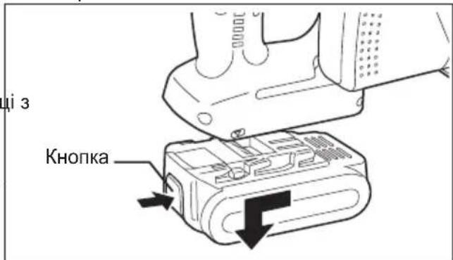
Man. 3
IV.Фуннкци氧HAHHЯ
Перед Викорпостанham iHctpymeNTa
IeHCTpyMeHT np3HaueHn IpaPi3aHHBnPo6IB 3 He3arapTOBaHO YoPHoro MeTany, KOJIbOpOBOro MeTany, DepeBa i nlaactMaCh. 3a CNNCKOM NOnOTeh, Rki MoXHa BnKOpNCTOByBaTu dna HAnEcxHO BnKOpNCtAHn Y BoRo IHCTpyMeHTy, 3BepHiTbcr Do po3diny "PpuaDJa". Jra 3MeHsHeHH Pn3NKy BnHNKHeHH TpaBMn, Heo6XiHo DToTPmYBaTnC4 3a3HaueHnx HxKYe 3anObixKnx 3ac06iB:
He pi3aTu 6araToawapObi MaTepiAn. PIXTe OndHy Detanb 3a pa3.
- He pi3aTn 3arapTOBaHy cTajb.
- Pizatn MaTepiAn, IINPOKa CTOpOHa OCHOBn kIX nepeBnUye 3aTNCHyTc TOpOHy MaTepiAny.
He TopkaTeCra roImmu pykamn do noNoTHa nnn, MaTepiany, o6o6pO6n8c8, a6o BiDpi3aHnx qactnH 6e3nocepEnb0 nicnaPi3aHH; BOHN MoKyTB o6neKTI uKipy.
KoXHoro pa3y niD yac BnKOpNCtAHN HCTpyMeH Heo6xIDHO nepeKoHaTnC, 00 Bin 3haxOaNTbcra Do6pomy po6oymy cTaHi.
BnKOpncToByTe 3a3HaueHn HnKHe KOHTpoIbHn nepenik nepeBipok:
- YI BCTAHOBJIeHO NOJOTHO B npabNJbHOMy NOno-JxehHi o6epTaHH?
CTpiKa Ha NOJOTHi NOBHHa Bka3yBaTH B TOMy X HApPmKy, 10 N CTpiKa Ha BepXHi KpnuI noJOTHa. - YN BCTaHOBJeHO NOJTOHO HAJIeXHIM YINOM?
IpekeohaTeCBA TOMy,IO WecTnpaHn 6oNT HadiHNO3aTMyHyTu.(MvB.MaN.6)
- YN BURJRAe NOJTOHcIJKOM 3aJIOBJbHO?
HeraHo 3aMiHiTb NOnOTHO, KaH Na HbOMy 6yb-aki TpiuHH a6o KaH 6yd-akn 3y6eub 3JamaHni. - 3aKpNBaeTbcra HxHn 3axnHn npncTp HaneXHM YINOM?
Man. 4
KaHcBcepeHHi NnNo36ipHnka e nn,HaTnCHiTb Ha KhoNky 6noKvBaHHa, Bi'edHaIte nNo36ipHnki BnDanitb nn. Picna cboRo BCTaHObitb NnNo36ipHnK Ha Micue.(Mn.B.Mn.5)
MaI.5
OBEPEXHO
Uo6 yHnKHyTN TpaBMn, He BnKOpNCTOByTe iHCTpyMeHT, kIIO HIXHI 3axnCHn IpnCTpi He 3aKnBaETbCRA WbNkO HaD NOJOTHOM NJI.
- Yu n ha i H O BCTaHOBJIeHn npo3Opn 3axnCHn npncTpii?
- 3apJxehn 6aTapeHn 6Iok i HnHaHIO BIn BCTaBHeH N B IHcTpymENT?
- Yu MiUHO 3aTMyTa raKa peYIIOBAHHrN6Hn?
- Yu HadiiHo 3aTyrHyTu Bnpi6, 0o o6pO6JrEeTbcra, Ha cTaHHI nnn a6o Ha Bepctaky?
- He 3a6ntn nnom nno36ipHk i nepedna Kpuka?
HaTnCHITb Ha KhoNkY 6NoKyBaHnI nepeHboI KpnuKn I BnDaJIb II, kNk CkyuNBCB BCEpuHi KpnuKn.
Kkuo KpnuKy 3abnTo NlOM, CKOpNCaTteCb dna OunueHHa DOBmnpedMeTom, HApNKpaD, pyHIO BnKpyTKOIO. Picra uboro 3akpnte nepedHIO KpnuKy. (INB.Man.4)
BctaHOBJIeHHI NOJOTHa
BukohaiTe 3a3HaeHi HxKye II:
- BntarHitb 6atapeHn6nK 3 iHcTpymEnty.
- BvdaJIb Bci o6pi3kn 30Hn noToHa nnI.
- CkopnCTaTecb BiKDnHOIO pyKOaTkoIO, 0o6 BiKHyTu (BiKpTu) HxHHi 3axnCHn npncTpI.
- BCTaHOBIb NOJIOHO, RIK NOKa3aHO Ha iINOCtpauii. (MnB.Man.6)
IpekeKaHaTeCra, 0o RaK HAprrMOK CTrpIKN NOJOTHi, TAK I HAprrMOK CTrpIKN Ha npO3OpOMy 3axnCHomy npncTpoi noJIoTHa Bka3yIOb B ODHOMY HAprrMKy.
- BCTaHOBiTb 3OBHIshIO waIby Ha MicCe.
- BCTABTe WeeTnrgpaHHN 6OJT.
- Ytpmyte KhoNky 6NoKyBaHHa HnHdHaHTNCHYtOMy NOOKeHHI. Ce BiDBePHe oBepTaHHa NOnToHa.
- HadiHIO 3aTARHITb WEcTnRpaHHN 6oNT WeecTnR paHHM KIIOUeM, IIO NOCTaBnaTbcra. CxObaTe WeecTnRpaHHN KIIOU.
PIMITKA:
36epiraTe 1eCTnrgaHHN KIOUy BIDcIKy 36epirAHHa Y Kopnyci MeTajOpi3aKa, KOIN Bn He KOpNCTyEtecB Hm.
OBEPEXHO
HeDToPImaHnHn BkA3iBOK MoKe npN3BeCTn Do BaxKnx TpaBM.
3HЯTTT NOJOTHa
YBAGA:
Bidpa3y nicna pi3aHH noTNO 6yde rapyHm. IpekoHaTeCra, 0o noTHO oxoJHO, nepeD TUM, k3Himatn Joro.
BnkoHaTe 3a3HaeHi HxKYe II:
- BuTgHiIb 6aTapeHmN 6nok 3 iHcTpymEnty.
- YtpmyTe KHOKky 6NOKyBaHHa HnHdJI B HaHaTNCHTOMy NOXeHHI. LcB iDBepeoepTaHHa noToHa.
- BnKOpncToBnyTe 8eCTnIpaHHN KJIIO, 10noCTaBnEbCra, 106 ocna6ntu WeeTnIpaHHN 6oNT.
ПРИMITKA:
B 36epiraTe WectnprHnn KInouy BiDciKy dna 36epiraHH, KOIN BIN He BnKOpNCTOByeTbcra.
- BntarHitb WectnurpaHHn 6oTt i 3OBHIu Hua6y.
- CkopnctaTtecb BiKnHOIO pyKOaTkoIO, 0o6 BiKNHyTN (BiKnPHTN) HxHHi 3axNCHI npncptpi.
- O6epeKHO 3HIMiTb NOJIoTHO NINJN.
- OuHCTiB IHCTpyMeHT B pa3i HEO6xIDHOCTI.
YBAGA:
BybTe oBepexHi, 06 He npiaTn Bawi pyKoIOTHom.
Bnndaoun noToH, 3arOpHitb noro B iJbHn a6o rofoBaHn nanip. Lc dOnomOKe BiDBepyTu npiN KOro-HeSyb BNKHyTM NIOOTHOM.
Man.6
IITiHIOHH6aTapeHn 6JOK PIMITKA:
Bau 6aTapeHn 6Iok He c NobHicTo 3apJxHeHMn iD qac npu6aHH. He 3a6yDbTe 3apAHTn nepeD BnKOpNCTaHHM.
3apdHn npncptpi (EY0L80)
- BBimKHiTb 3apJHn npicTpI B wTeNceJbHy a po3ETky 3miHHoro cTpMy.
ПРИМITA:
PnPiKIOUeHHI WTeNcIbHOI BUNKIO D0
DKepeJa KINBIIeHn 3MIHNM CTpyMOM MOKyTb
3'YBNTuCA IcKn, aJe ue He CTBOpyIO npo6NeMy 3
TOUY 3OPY 6e3neKn.
- ⅢJIbHO BCTaBTe 6aTapeHn 6JOK B 3apAHN npucTpi.
1 3piBnIte MiTKu BnpiBHOBaHHa i po3M 6aTapeio y 3arNl6JIeHHi Ha 3apdHomy npucTpoi.
2 3cynbTe Ioro Bpeepy HnpanMky cTpiJKN.
3.ПдчacЗардкбуde ropiTNЯmnoчkaЗapдкп.пслязавршенизардкнabTOMaTHUcHcnpaIOE BHyTpIiHi eJIeKTPoHHn nepemKauch,3anobiraqunHaMiphi 3apdci.
3apka He noHcTbC, kUo 6aTapeHn 6Iok e HADTO rapaHm (HaPnKnaD, 6e3nocepEnhbo nicJyHKioHyBaHH npu BeNIkOMy HabaHTaxeHHi).
OpaHKeBa NaMNoUka peXmMy ouikyBaHHa 6ynde MrrTu, DOKN 6atape He oxonoHe.
B OCHOBHOMy IJIaPi3aHHIepeBHNH
POnToH0 PnJIN 3 TBepDocPnabHnMpiKyuMn
JIaactHAmn Dn piaHH ToHKoI DepeBHH
(doatkoBepnila)
- EY9PW13B
Дя pi3aHHToHkoI DepeBHH, KaO noTpipHa qnta pixyka Kpomka
PekomeHIOBaHa TOBUNHa MaTepiany - 10 12 MM
Hn HnoToHO nnn 3 TBepocnabHnMn pixyumn H nactnHaMn dpo pi3aHHn nnaCTmacn (doataKobeyornpnana)
- EY9PP13B
EY971045422 H2102 Printed in China