EY4541 - Saw PANASONIC - Free user manual and instructions
Find the device manual for free EY4541 PANASONIC in PDF.
User questions about EY4541 PANASONIC
0 question about this device. Answer the ones you know or ask your own.
Ask a new question about this device
Download the instructions for your Saw in PDF format for free! Find your manual EY4541 - PANASONIC and take your electronic device back in hand. On this page are published all the documents necessary for the use of your device. EY4541 by PANASONIC.
USER MANUAL EY4541 PANASONIC
Before operating this unit, please read these instructions completely and save this manual for future use.
Thank you for purchasing the Panasonic Jigsaw. This jigsaw can be used with Panasonic rechargeable batteries to provide excellent cutting performance. The jigsaw is for cutting metal, wood, and drywall only.
Read the "Safety Instructions" booklet and the following before using.
II. ADDITIONAL SAFETY RULES
1) Hold tool by insulated gripping surfaces when performing an operation where the cutting tool may contact hidden wiring. Contact with a "live" wire will also make exposed metal parts of the tool "live" and shock the operator.
2) Use clamps or another practical way to secure and support the workpiece to a stable platform. Holding the work by hand or against your body leaves it unstable and may lead to loss of control.
3) Keep hands away from cutting area and blade. Keep your insulated gripping surfaces. If both hands are holding the tool, they cannot be cut by the blade.
4) Never hold piece being cut in your hands or across your leg. It is important to support the work properly to minimize body exposure or loss of control.
5) Be aware that this tool is always in an operating condition, since it does not have to be plugged into an electrical outlet.
6) Always use safety goggles or glasses with side shields. Ordinary eye or sun glasses are NOT safety glasses.
7) When this tool is used for woodworking in confined areas (e.g. indoors), wear dust mask.
8) Avoid cutting nails. Inspect workpiece for any nails and remove them before operation.
9) Do not cut oversized workpiece.
10) Check for the proper clearance beyond the workpiece before cutting so that the blade will not strike the floor, workbench, etc.
11) Hold the tool firmly.
12) Make sure the blade is not contacting the workpiece before the switch is turned on.
13) Keep hands away from moving parts.
14) Do not touch the blade or workpiece immediately after operation; they may be extremely hot and could burn your skin.
15) Never swing tool.
16) Do not use blades which are deformed or cracked.
17) Do not use blades which do not comply with the characteristics specified in these instructions.
18) Remove the battery pack from the tool body before replacement of the blade, making adjustments, or other maintenance work.
19) Wear ear protectors when using the tool for extended periods.
| Symbol | Meaning |
| V | Volts |
| --- | Direct current |
| n | No load speed |
| ...min-1 | Revolutions or reciprocations per minutes |
| Ah | Electrical capacity of battery pack |
| To reduce the risk of injury, user must read and understand instruction manual. | |
| For indoor use only. | |
WARNING:
- Do not use other than the Panasonic battery packs that are designed for use with this rechargeable tool.
- Do not dispose of the battery pack in a fire, or expose it to excessive heat.
- Do not drive the likes of nails into the battery pack, subject it to shocks, dismantle it, or attempt to modify it.
- Do not allow metal objects to touch the battery pack terminals.
- Do not carry or store the battery pack in the same container as nails or similar metal objects.
- Do not charge the battery pack in a high-temperature location, such as next to a fire or in direct sunlight. Otherwise, the battery may overheat, catch fire, or explode.
- Never use other than the dedicated charger to charge the battery pack. Otherwise, the battery may leak, overheat, or explode.
- After removing the battery pack from the tool or the charger, always reattach the pack cover. Otherwise, the battery contacts could be shorted, leading to a risk of fire.
III.ASSEMBLY
WARNING:
To reduce the risk of injury, always remove battery pack before changing the blade.
Inspection before use
- Has the correct jigsaw blade been attached for the object to be cut?
- Has the correct stem shape and thickness of the blade been mounted?
- Check if the blade is fixed securely?
- Check if the blade is cracked or broken.
- Check that there are no foreign objects in the object to be cut.
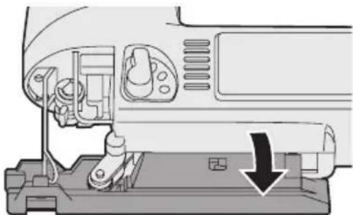
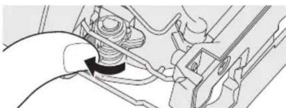
Installing and removing the blade Installation
- Wipe away any cutting dust from the blade and the blade clamp bracket.
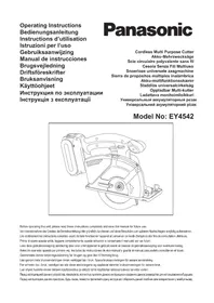
- Lift up the blade Attach/Remove lever.
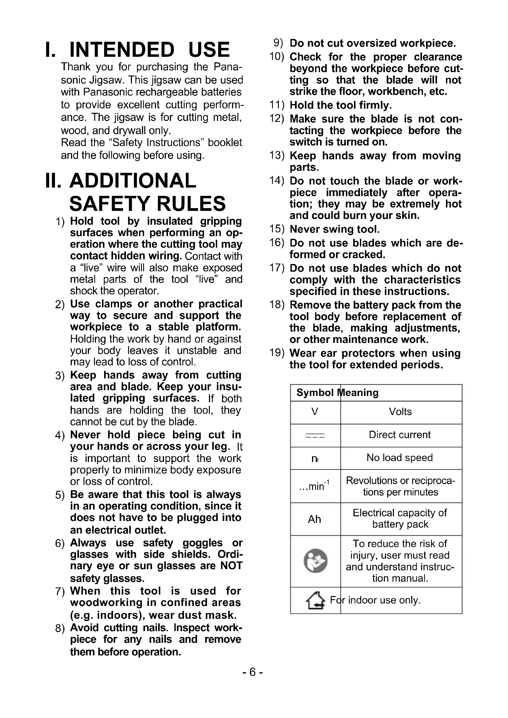
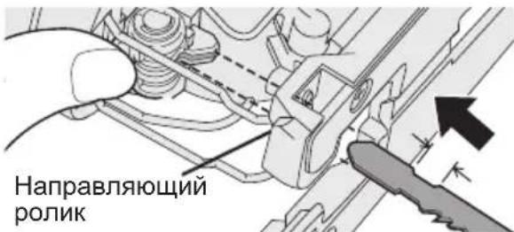
- Insert the blade into the blade clamp bracket and set the back of the blade along the roller guide so that the back of the jigsaw blade slides along the roller guide.
-
Release the blade Attach/Remove lever.
-
When the blade is secured in place then lever will return to its original position.
- Check that the back of blade is setting in the groove in the roller guide.
WARNING:
If you do not insert the saw blade deep enough, the saw blade may be ejected unexpectedly during operation. This can be extremely dangerous.
Removal
- Lift up the blade Attach/Remove lever.
- Pull out the blade.
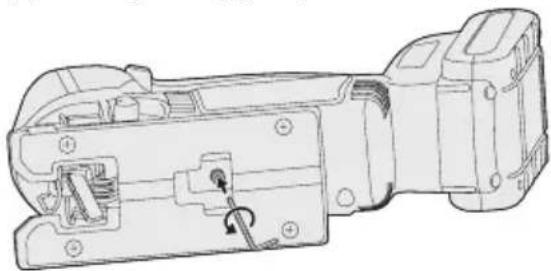
Adjusting the base
- Use the hex wrench to loosen the base fixing screw.
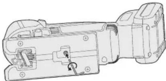
-
Move the base along the base adjustment hole to set its position. (See the diagram at right.)
-
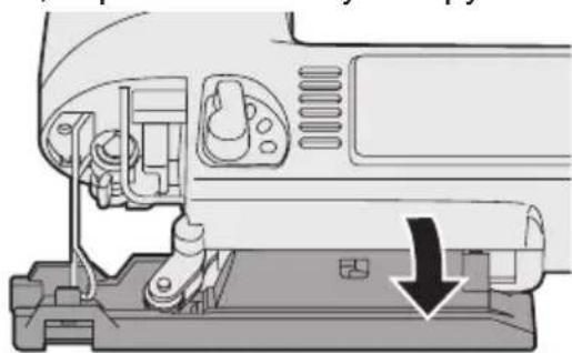
The base can be adjusted to between 0^ and 45^ sideways and the forward/back position can also be adjusted. If tilting the base sideways, remove the dust cover first.
Refer to the bevel index to determine the angle. - Rip fence fixing screw should be located on the opposite side tool is beveled.
- Use the hex wrench to tighten the base fixing screw.
Position of base and purpose of use
| Base adjustment hole position | Purpose of use |
| Normal right-angled cutting | |
| Cutting at an angle between 0° and 45° | |
| Cutting at an angle of 45° | |
| Cutting close to the end of a wall |
NOTE:
This is only a rough guide. The actual angle of the cut will be affected by factors such as the way the tool is held against the surface.
Adjusting the orbital stroke mode
- Adjust the orbital stroke mode to the object to be cut.
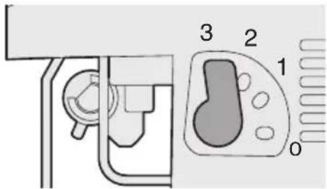
| Lever position | Blade movement | Main applications |
| 0 | Vertical only | • Cutting hard metals such as steel • Smooth cutting of building materials and plywood boards • Cutting around small curves |
| 1 | Low orbital stroke mode | • Cutting softer metals such as aluminum and other non-ferrous metals • Cutting hardwood, plywood boards and plastics |
| 2 | Medium orbital stroke mode | • Cutting fairly soft materials • Cutting wood and composite boards • High-speed cutting of aluminum and soft steel |
| 3 | High orbital stroke mode | • Cutting soft materials • High-speed cutting of materials such as wood, composite boards and plastics |
- If you would like to produce a cleaner finish, set the orbital stroke mode to a lower level.
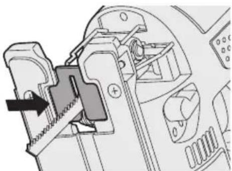
Anti-splintering plate
Use the anti-splintering plate to reducing splinter while cutting wood.
Installation
-
Set the base at 90 degree position.
-
Place the anti-splintering plate on the underside of the base, and gently push it to be installed.
-
Install so that the beveled edge of the slot in the middle of the anti-splintering plate is facing toward the jigsaw.
Dust adapter for vacuum cleaner (EY9H009E) (Available as an accessory, not included)
You can use a vacuum cleaner to collect cutting dust while cutting.
Installation
- Attach the hook of the dust collection adapter to the front of the base.
- Snap the rear to install it.
- Attach the hose of the vacuum cleaner.
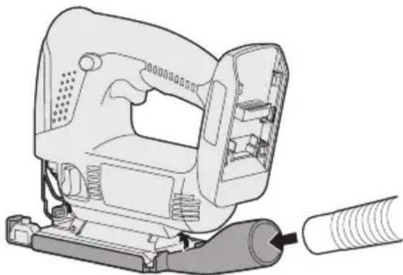
- It is recommended to use a dust adapter for reducing the risk of damaging the surface of the object being cut.
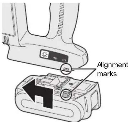
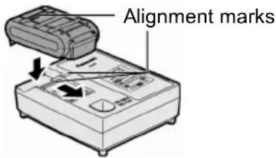
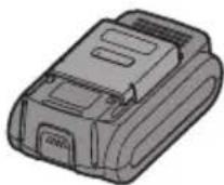
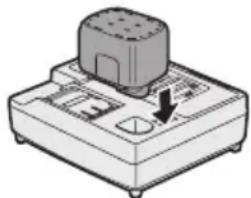
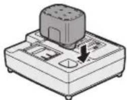
Attaching or Removing Battery Pack
- To connect the battery pack:
Line up the alignment marks and attach the battery pack.
- Slide the battery pack until it locks into position.
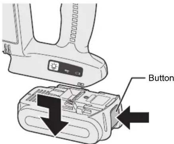
- To remove the battery pack:
Push on the button from the front to release the battery pack.
IV. OPERATION
- Push the switch lock lever down, pull the power switch.
The speed increases with the amount of depression of the power switch.
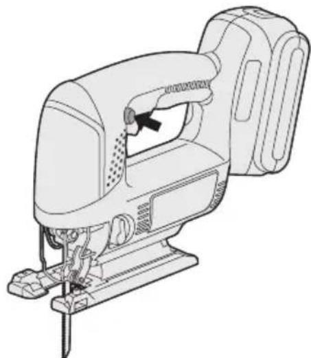
- Once cutting is finished, release the power switch.
- Check that the temperature of the blade has dropped sufficiently, and then remove the blade.
Cutting
NOTE:
- Check that there are no obstacles to cut underneath workpiece.
- Check that there are no objects such as nails in the material to be cut. If the blade comes into contact with any such objects during cutting, a strong reaction force will be generated and severe injury may occur.
- Do not place your hand on the object in the direction cutting is to take place. If this is not observed, there is a risk of injury.
- Do not touch the jigsaw blade immediately after cutting. If this is not observed, burns may occur.
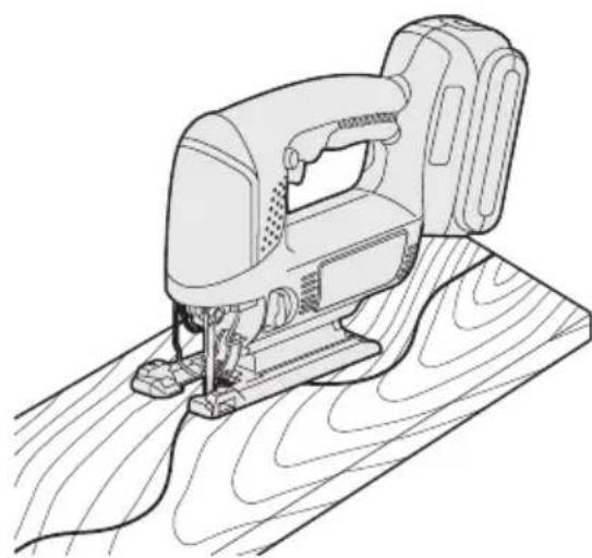
Cutting along marked lines
-
Place the object to be cut onto the base, and align the blade with the marked line.
-
Do not touch the blade against the object to be cut before pulling the power switch.

-
Pull the power switch, wait until the speed has stabilized, and then place the base against the object to be cut and cut along the marked lines.
-
When cutting complex shapes such as shapes with many small curves, reduce the cutting speed and the turning speed.
Plunge cutting
-
Make a drill hole in the section to be plunge cut in order to let the blade pass through.
-
Insert the blade into a hole without touching the workpiece, and then turn on the power switch.
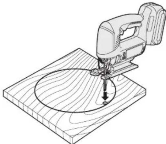
- Cut along the marked line.
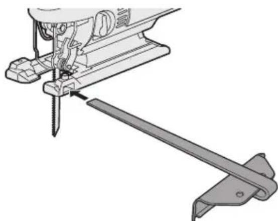
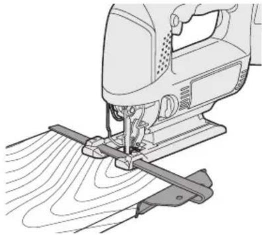
Using a rip fence (EY9X011E) (Available as an accessory, not included)
A rip fence can be used for cutting parallel lines and for cutting circles and arcs.
Installing the rip fence
- Loosen the rip fence fixing screw.
- Pass the rip fence through the mount.
- Adjust the cutting position and then tighten the fixing screw.
Cutting at the same width
- Place the base onto the workpiece so that the edge of the rip fence and workpiece are put together.
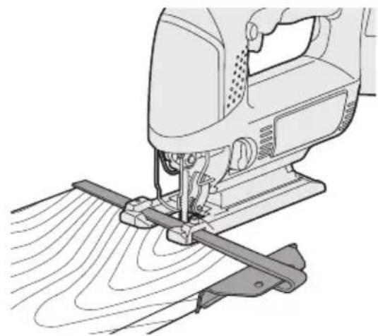
- Without letting the blade touch the workpiece, turn on the power switch.
- Face the rip fence firmly to the workpiece to cut parallel line.
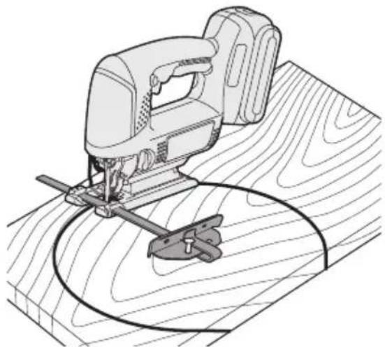
Cutting circles
- If cutting away a section, make a drill hole on workpiece to let the jigsaw blade pass through.
- Align the pin hole of the rip fence with the center of the circle, and then use a nail or screw to hold the object in place.
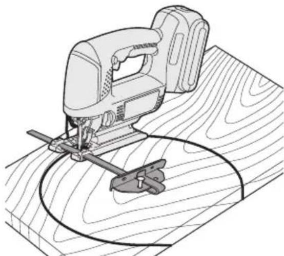
- Without touching the workpiece, turn on the power switch.
- Cut along the marked line.
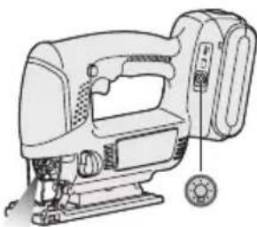
Control Panel
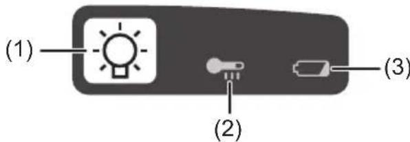
(1) LED light
Before the use of LED light, always pull the power switch once.
Press the LED light button.
The light illuminates with very low current, and it does not adversely affect the performance of the driver during use or its battery capacity.
CAUTION:
- The built-in LED light is designed to illuminate the small work area temporarily.
- Do not use it as a substitute for a regular flashlight, since it does not have enough brightness.
- LED light turns off when the tool has not been used for 5 minutes.
Caution: DO NOT STARE INTO BEAM. Use of controls or adjustments or performance of procedures other than those specified herein may result in hazardous radiation exposure.
(2) Overheat warning lamp

Off (normal operation)


- Flashing: Overheat
- Indicates operation has been halted due to battery overheating.
The overheating protection feature halts operation to protect the battery pack in the event of overheating. The overheat warning lamp on the control panel flashes when this feature is active.
- If the overheating protection feature activates, allow the driver to cool thoroughly (at least 30 minutes). The battery is ready for use when the overheat warning lamp goes out.
- Avoid using the driver in a way that causes the overheating protection feature to activate repeatedly.
(3) Battery low warning lamp

Off (normal operation)


Flashing (No charge) Battery protection feature active
Excessive (complete) discharging of lithium ion batteries shortens their service life dramatically. The tool includes a battery protection feature designed to prevent excessive discharging of the battery pack.
- The battery protection feature activates immediately before the battery loses its charge, causing the battery low warning lamp to flash.
- If you notice the battery low warning lamp flashing, charge the battery pack immediately.
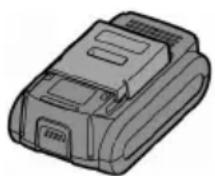
[Battery Pack]
For Appropriate Use of Battery pack
Li-ion Battery pack (EY9L40/ EY9L41)
- For optimum battery life, store the Li-ion battery pack following use without charging it.
- When charging the battery pack, confirm that the terminals on the battery charger are free of foreign substances such as dust and water etc. Clean the terminals before charging the battery pack if any foreign substances are found on the terminals.
The life of the battery pack terminals may be affected by foreign substances such as dust and water etc. during operation.
- When battery pack is not in use, keep it away from other metal objects like: paper clips, coins, keys, nails, screws, or other small metal objects that can make a connection from one terminal to another.
Shorting the battery terminals together may cause sparks, burns or a fire.
- When operating the battery pack, make sure the work place is well ventilated.
- When the battery pack is removed from the main body of the tool, replace the battery pack cover immediately in order to prevent dust or dirt from contaminating the battery terminals and causing a short circuit.
Battery Pack Life
The rechargeable batteries have a limited life. If the operation time becomes extremely short after recharging, replace the battery pack with a new one.
Battery Recycling
ATTENTION:
For environmental protection and recycling of materials, be sure that it is disposed of at an officially assigned location, if there is one in your country.
[Battery Charger]
Charging
Cautions for the Li-ion Battery Pack
- If the temperature of the battery pack falls approximately below -10^ (14^) , charging will automatically stop to prevent degradation of the battery.
Common Cautions for the Li-ion/Ni-MH/Ni-Cd Battery Pack
- The ambient temperature range is between 0^ (32^) and 40^ (104^) . If the battery pack is used when the battery temperature is below 0^ (32^) , the tool may fail to function properly.
- When charging a cool battery pack (below 0^ (32^) ) in a warm place, leave the battery pack at the place and wait for more than one hour to warm up the battery to the level of the ambient temperature.
- Cool down the charger when charging more than two battery packs consecutively.
- Do not insert your fingers into contact hole, when holding charger or any other occasions.
CAUTION:
To prevent the risk of fire or damage to the battery charger.
- Do not use power source from an engine generator.
- Do not cover vent holes on the charger and the battery pack.
- Unplug the charger when not in use.
Li-ion Battery Pack
NOTE:
Your battery pack is not fully charged at the time of purchase. Be sure to charge the battery before use.
Battery charger (EY0L80)
- Plug the charger into the AC outlet.
NOTE:
Sparks may be produced when the plug is inserted into the AC power supply, but this is not a problem in terms of safety.
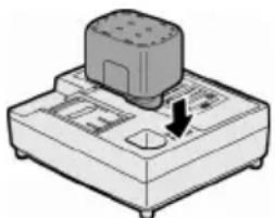
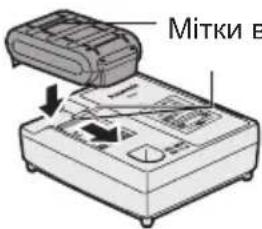
-
Insert the battery pack firmly into the charger.
-
Line up the alignment marks and place the battery onto the dock on the charger.
- Slide forward in the direction of the arrow.
- During charging, the charging lamp will be lit.
When charging is completed, an internal electronic switch will automatically be triggered to prevent overcharging.
- Charging will not start if the battery pack is warm (for example, immediately after heavy-duty operation).
The orange standby lamp will be flashing until the battery cools down.
Charging will then begin automatically.
- The charge lamp (green) will flash slowly once the battery is approximately 80% charged.
- When charging is completed, the charging lamp will start flashing quickly in green color.
- If the temperature of the battery pack is 0^ or less, charging takes longer to fully charge the battery pack than the standard charging time.
Even when the battery is fully charged, it will have approximately 50% of the power of a fully charged battery at normal operating temperature.
- If the power lamp does not light immediately after the charger is plugged in, or if after the standard charging time the charging lamp does not flash quickly in green, consult an authorized service center.
- If a fully charged battery pack is inserted into the charger again, the charging lamp lights up. After several minutes, the charging lamp may flash quickly to indicate the charging is completed.
Ni-MH/Ni-Cd Battery Pack
NOTE:
When you charge the battery pack for the first time, or after prolonged storage, charge it for about 24 hours to bring the battery up to full capacity.
Battery charger (EY0L80)
- Plug the charger into the AC outlet.
NOTE:
Sparks may be produced when the plug is inserted into the AC power supply, but this is not a problem in terms of safety.
- Insert the battery pack firmly into the charger.
- During charging, the charging lamp will be lit.
When charging is completed, an internal electronic switch will automatically be triggered to prevent overcharging.
- Charging will not start if the battery pack is warm (for example, immediately after heavy-duty operation).
The orange standby lamp will be flashing until the battery cools down. Charging will then begin automatically.
- When charging is completed, the charging lamp will start flashing quickly in green color.
- If the charging lamp does not light immediately after the charger is plugged in, or if after the standard charging time the charging lamp does not flash quickly in green, consult an authorized service center.
- If a fully charged battery pack is inserted into the charger again, the charging lamp lights up. After several minutes, the charging lamp may flash quickly to indicate the charging is completed.
LAMP INDICATIONS

Green Lit
Charger is plugged into the AC outlet.
Ready to charge.

Green Flashing Quickly
Charging is completed. (Full charge.)

Green Flashing
Battery is approximately 80% charged. (Usable charge. Li-ion only.)

Green Lit
Now charging.

Orange Lit
Battery pack is cool.
The battery pack is being charged slowly to reduce the load on the battery. (Li-ion only.)

Orange Flashing
Battery pack is warm. Charging will begin when temperature of battery pack drops.

If the temperature of the battery pack is -10^ or less, the charging status lamp (orange) will also start flashing.
Charging will begin when the temperature of the battery pack goes up (Li-ion only).

Charging Status Lamp
Left: green Right: orange will be displayed.
Both Orange and Green Flashing Quickly
Charging is not possible. Clogged with dust or malfunction of the battery pack.
Information for Users on Collection and Disposal of Old Equipment and used Batteries
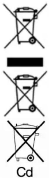
These symbols on the products, packaging, and/or accompanying documents mean that used electrical and electronic products and batteries should not be mixed with general household waste.
For proper treatment, recovery and recycling of old products and used batteries, please take them to applicable collection points, in accordance with your national legislation and the Directives 2002/96/EC and 2006/66/EC.
By disposing of these products and batteries correctly, you will help to save valuable resources and prevent any potential negative effects on human health and the environment which could otherwise arise from inappropriate waste handling.
For more information about collection and recycling of old products and batteries, please contact your local municipality, your waste disposal service or the point of sale where you purchased the items.
Penalties may be applicable for incorrect disposal of this waste, in accordance with national legislation.
For business users in the European Union
If you wish to discard electrical and electronic equipment, please contact your dealer or supplier for further information.
[Information on Disposal in other Countries outside the European Union]
These symbols are only valid in the European Union. If you wish to discard these items, please contact your local authorities or dealer and ask for the correct method of disposal.
Note for the battery symbol (bottom two symbol examples):
This symbol might be used in combination with a chemical symbol. In this case it complies with the requirement set by the Directive for the chemical involved.
V. MAINTENANCE
Use only a dry, soft cloth for wiping the unit. Do not use a damp cloth, thinner, benzine, or other volatile solvents for cleaning.
VI. ACCESSORIES
CAUTION:
- The use of any accessories not specified in this manual may result in fire, electric shock, or personal injury. Use recommended accessories only.
Metal Blade
-EY9SXMJ0E
For cutting metal in general
Wood Blade
-EY9SXWJ0E
For cutting wood in general
Drywall Blade
- EY9SXXJ0E
For cutting drywall in general
Rip Fence (Optional accessory)
- EY9X011E
For convenience of rip cuts and repeated cut of same width.
Dust Adaptor for Vacuum Cleaner (Optional accessory)
-EY9X009E
VII.SPECIFICATIONS
MAIN UNIT
| Model | EY4541 | |
| Motor | 14.4 V DC | |
| Max thickness of mounting blade | 1.3 mm (1/16") | |
| Length of strokes | 20 mm (25/32") | |
| Strokes per minute | 0 - 2400 /min | |
| Maximum cutting capacities | Wood | 65 mm (2-9/16") |
| Mild steel | 6 mm (1/4") | |
| Aluminum | 10 mm (3/8") | |
| Overall length | 270 mm (10-5/8") | |
| Weight (with battery pack: EY9L40) | 2.2 kg (4.8 lbs) | |
| Weight (with battery pack: EY9L41) | 2.25 kg (5 lbs) | |
| Noise, Vibration | See the included sheet | |
BATTERY PACK
| Model EY9L40 | EY9L41 | |
| Storage battery | Li-ion Battery | |
| Battery voltage | 14.4 V DC (3.6 V x 4 cells) | |
| Capacity 3 Ah 3,3 Ah | ||
BATTERY CHARGER
| Model | EY0L80 |
| Rating | See the rating plate on the bottom of the charger. |
| Weight | 0.95 kg (2.1 lbs) |
[Li-ion battery pack]
| Charging time | 3 Ah | 14.4 V 21.6 V | 28.8 V | |
| EY9L40 | EY9L60 | EY9L80 | ||
| Usable: 35 min. | Usable: 45 min. | Usable: 55 min. | ||
| Full: 50 min. | Full: 60 min. | Full: 70 min. |
| Charging time | 3.3 Ah | 14.4 V | ||
| EY9L41 Usable: 45 min. Full: 60 min. |
[Ni-Cd/Ni-MH battery pack]
| Charging time | 7.2 V 9.6 V 12 V 15 | 6 V 18 V 24 V | |||||
| 1.2 Ah | EY9065 | EY9080 | EY9001 | ||||
| EY9066 | EY9086 | EY9006 | |||||
| 20 min. | |||||||
| 1.7 Ah | EY9180 | EY9101 | |||||
| EY9182 | EY9103 | ||||||
| 25 min. | |||||||
| 2 Ah | EY9168 EY9188 | EY9106 | EY9136 | EY9116 | |||
| EY9107 | EY9117 | ||||||
| EY9108 | |||||||
| 30 min. 60 min. | |||||||
| 3 Ah | EY9200 | EY9230 | EY9210 | 90 min. | |||
| 45 min. | |||||||
| 3.5 Ah | EY9201 | EY9231 | EY9251 | ||||
| 55 min. 65 min. | |||||||
NOTE: This chart may include models that are not available in your area. Please refer to the latest general catalogue.
NOTE: For the dealer name and address, please see the included warranty card.
ONLY FOR U. K.
VIII. ELECTRICAL PLUG INFORMATION
FOR YOUR SAFETY PLEASE READ THE FOLLOWING TEXT CAREFULLY
This appliance is supplied with a moulded three pin mains plug for your safety and convenience.
A 5 amp fuse is fitted in this plug.
Should the fuse need to be replaced please ensure that the replacement fuse has a rating of 5 amp and that it is approved by ASTA or BSI to BS1362.
Check for the ASTA mark or the BSI mark on the body of the fuse.
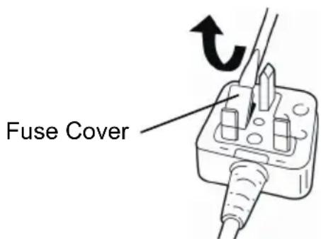
If the plug contains a removable fuse cover you must ensure that it is refitted when the fuse is replaced.
If you lose the fuse cover the plug must not be used until a replacement cover is obtained.
A replacement fuse cover can be purchased from your local Panasonic Dealer.
IF THE FITTED MOULDED PLUG IS UNSUITABLE FOR THE SOCKET OUTLET IN YOUR HOME THEN THE FUSE SHOULD BE REMOVED AND THE PLUG CUT OFF AND DISPOSED OF SAFELY.
THERE IS A DANGER OF SEVERE ELECTRICAL SHOCK IF THE CUT OFF PLUG IS INSERTED INTO ANY 13 AMP SOCKET.
If a new plug is to be fitted please observe the wiring code as shown below.
If in any doubt please consult a qualified electrician.
IMPORTANT:
The wires in this mains lead are coloured in accordance with the following code:
Blue: Neutral
Brown: Live
As the colours of the wire in the mains lead of this appliance may not correspond with the coloured markings identifying the terminals in your plug, proceed as follows.
The wire which is coloured BLUE must be connected to the terminal in the plug which is marked with the letter N or coloured BLACK.
The wire which is coloured BROWN must be connected to the terminal in the plug which is marked with the letter L or coloured RED.
Under no circumstances should either of these wires be connected to the earth terminal of the three pin plug, marked with the letter E or the Earth Symbol 1三
How to replace the fuse: Open the fuse compartment with a screwdriver and replace the fuse and fuse cover if it is removable.
This apparatus was produced to BS800.
Pacco battery Li-ion
NOTA:
[Pacco battery Li-ion]
| Tempo di caricamento | 3 Ah | 14,4 V 21,6 V 28,8 V | ||
| EY9L40 | EY9L60 | EY9L80 | ||
| Utilizzabile: 35 min. | Utilizzabile: 45 min. | Utilizzabile: 55 min. | ||
| Completa: 50 min. | Completa: 60 min. | Completa: 70 min. | ||
| Tempo di caricamento | 3,3 Ah | 14,4 V | ||
| EY9L41 | Utilizzabile: 45 min. | |||
| Completa: 60 min. | ||||
Skjaering langs merkete linjer
(2) Varsellampe for overoppheting

Av (normal operation)


Av (normal operation)
Blinker (Ingen lading) Battery protection feature active
V. VEDLIKEHOLDV. VEDLIKEHOLD
Bruk kun en torr, myk klut for a törke encheten. Bruk/DDke en fuktig klut, tynner, bensin erer andre flytende lsemidler til rengjoring.
VI. TILBEHØRVI. TILBEHØR

FORSIKTIG:
- Bruk av ekstrautstyr som/DD er spesifisert i donne veiledningen kan fore til brann, elektrisk stot ell personskader. Bruk kun anbefalt utstyr.
Metalblad
-EY9SXMJ0E
LAMPUN MERKINNÄTLAMPUN MERKINNÄT
III. CBOPKAII. CBOPKA
OCTOPOXHO:
IЯ CHNXEHNpaCKa NOnyeHn TpaBMBI nepe3ameHO NJIKN O6raTeNbHOOTCOeINHIne aKKyMylrTOpHbI 6NOK.
OcmoTp nepei hauanom pa6oTbI
- PpOBePbTe npaBnIbHocTb Bbl6opa nnIKn dIy o6pa6aTbIbAemOJ deTann.
-БыллусановленшТОК NOДхODЯ- 贝 士 营 Mbl C COOTBETCTBYU OSeI TOLIUNHOJNe3BNA? - PpOBePbTe HaDeJxHocTb 0nKcaunnn
- PpOBepbTe pNlky Ha OTCyTCTBne TpeuH npa3pbIBOB.
-ПюверьтЕ OTCYТСВИЕ NOCTOPOHHINx DeTaNeн Ha obpa6aTbIbAeMoN DeTaJIH.
YcTaHOBka N ChrTne NIIKN
YctaHOBka
- PpOtpnTe OT nbIIN NOIOTHO 3aXIM nnJKN.
2.ПОДнHMntepbIyar yCTaHOBKN/CHYTINNJIKN.
- BCTaBbTe Ne3BnE B KPOHHTeH n ycTaHOBtTe 6bpaTHyO CTOpOHy Ne3BnB BDoIb POINKOBOn HAnpaBnHOUseN TaK, YTO6bl Ne3BnE HOXOBKn CKoJIb3nIO NpONIKOBOn HAnpaBnAOUeN.
4.ПОДнIMITEpbIyar yCTaHOBKN/CHYTIN NJIKN.
-
Pocne 6nKcaun NnJKN BepHnte pbIyarB nepBOHaayalbHOe NOJXKeHne.
-
Y6eIITecb B TOM, yTO o6paTHa CToPOHa NIIKN HaxoDNTc8 TOUHO B KaHABKe HAnpabNIAOUIOero pONka.

OCTOPOXHO:
Ecnn nnka He 6ydt yctaHOBneHa doCTaTOUHO Iny6OKO, OHa MOKeT HeoXnDaHHo BbICKOHTb BO BpeM pa60Tbl.3To ouehb onaCHO.
CHaTne
1.ПоднIMTe рьчаг установк/сятneyпИКИ.
2. BbIyHInTe nnKy.
PergunpoBka onopbl
- C nOMOsbH o WeCTnIrpaHHoro KJIoua OTKpyTnte 0HKcnpyUoN BnHT onOpbl.
2.Перединые onopy BdoJIpeRyInpoBOUHOrO OTBepCTnI N Bbl6epNTe HxKHOeNoJoxHeNc.(Cm.pncyHOK cnpaBa.)
Onopy moxno pa3BepHyb B cTOpohy Ha yroI OT 0^ do 45^ n Kpome 3Toro nepeMeCTnBnepei/Ha3aI. Pnp Heo6XOIMOCTN BblONHHTb HaKIOH, CHMNTe PbIe3aUHTHyO KpbIuKy.
-Дя onpeJeHnY yIa noIb3yITeCb rpaDynpoBaHHoI uKaIOn.
-ФИКСИРУОПМ BINT HANpaBnIQUSEI ПАнкДОЛЖЕН HAXODITbCЯ HA CTOpOHe,OBpaTHOH HAKNHOH INHCTpyMeHTa.
3.ДЯЗakpyuBaHnraJbHOrOckpeNJaIooIeRoBVHTaNCNoJIb3yIteWeCTurpaHHbIKIOU.
- y6eIntecb B OTCyTCTBnH NOMEX NOI o6pa6aTbIBaEMbIM N3DeJIneM.
- Y6eIHTecb B OTCyTCTBnB O6pa6aTbIBaEMOM N3dJIIM MeTALINueCKNX DeTaNen, HAnpIMep, rBO3deN.
Pn BXOXKeHn NJIKN BO BpeMnIeHnB KOHTaKT C TaKoN DeTaJIbBO3MOxEH pe3Kn OTBeTHbYdap, cNoCo6HbH HaHeCTN 3HaUHTeNbHbIe yBeYb.
He KlaIte pyKn Ha o6pa6aTbIBaemyo DeTaB B HApPabNeHn DBrXeHnA HcTpymEHTa.
Pn HeBbIOnHeHnaDaHHoro yCNOBn cyEcTByeT pNCK nOyuEHNr TpaBM.
He kacaitecB nIkn cpa3y ke nocne npekpaaeHn pa60tbl.
B npOTNBHOM cIyuae Bbl MOKeTe noJnyuHTb OXOr.
- BkIIOUHTe NITaHHe, DOXKNTecb Do Tex NOP, NOKa He Cta6nIN3npyETcR CKoPocTb, yCTaHOBNTe INIKy HAnpOTNB OTMeueHHOn JINHHN I NaHHTe NJIJeHHe.
- YctaHOBIne onOpy Ha o6pa6aTbIbAemoe H3dJIne TaK, UTo6bl KpaN3dJIINc CoPnKacJcC HAnPaBnIooi E NlaHKOJ.
- He kacacb nIkoI o6pa6aTbIbAemoro 13deJnBkHouHTb NITaHHe.
- UTo6bI pe3aTb no npapannelbHbIM IHHnAM, NOBepHnTe HAnpaBJIHOUo INaHKy K O6pa6aTbIBaEMO JEtAnN.
BbinnnBaHne KpNBbIX
- B cnyuae, ecn npoHnBbINOHNYe c KpaIO, npocBepnTe DpeIbIO OTBepCTne B n3dEJIIN I npocyHbTe Tyda NnKy lo63nka.
- BbipOBHnTe OTBepCTne B HappaBnIou- Ⅲe INaHKe C cHTpOM OTBepCTnB N3- DeJINN IN BCTaBBte rBO3db INN BNHT dJIy UdepXnBaHHn N3deJIn Ha MeCTe.
- He kacacb o6pa6aTbIbAemoro n3deJnra, BkIIOHTe NITaHne.
- BbInonHnTe nIeHne no OTMeueHHbIM JINHnM.
Iamna NOcBETKn NOTpe6JrEt OueHb Hn3KnTOK n He OKa3bIBaetOTpuuataTeNbHOBO3DeNCTBnHa IPOUN3BO-DNTeJIbHOCTb INHCTpyMeHTa Nn Ha EMKOCTbAKKMyJrTOpOB.
BHIMAHNE:
BCTpoEHnA CBeTOnoHnA NOcCBetKa npEHa3NaYeHa dJa OCBeUeHnA He6OJbWOn pa6Oey 3OHBi B TeueHne KOpOTKOrO IpOMeKyTKa BpeMeHn.
He nCnoJb3yIte ee B KaueCTBe NocToHHoro fOHaPika, TaK KaK OHa He 06naAdet DOCTaTOHOn JPKoCTbHO.
CBeToIOHnA JAMNa BbIKNoUaETcA,ecn INCTpyMeHT He NcNoIb3YeTcB TeueHne 5 MNHyT.
BnmaHne:HE CMOTPETb HA JyU. IcnoIb3ObaHne opraHOB ynpaBHeHn IIN peRyInpoBOK,JI60 BblIOJHeHne npOeDyp INbIM o6pa3OM,YeM yka3aHO B DaHHo IHCTpyKuN,MOKeT pPbBeCTN K IOnaDaHIO NOB 03DeEChTBne ONaCHOrO N3Jyehn.
(2) Праздупөгддөцая памночka peperpeba

BbIKIIOueHa (obbyHna pa60ta)


Muraet: Neperpeb
Yka3bIbAeT Ha To, YTo
pa6ota 6bla octaHOBJIeHa
n3-3a NeperpeBa 6atapen.
Функця 3auntbI OT neperpeBa OCTaHabnBaet pa6oty INHCTpyMeHTaДЯ 3aunTbI aKKymyTOpHOrO 6NoKa B Cnyuee ero neperpeBa. Ecnn FynKzir 3aunTbI OT neperpeBa BKlUoyeha, He naHeN ynpablenHa Mraet npedynpeKdaUoJЯ lamnoouka.
Bcnyae BkIIOUeHnA cyHKun 3a-ntbOt npepeBa daTe dpEnoCTbTb B TeueHne npOOnKInTeNbHO BpemeHn (He Mehee 30 MNHyT). AkKymyIaTOpbI rOToBbl K pa6ote nocJIe BbIKIOUeHn IpeDynpexJaIoUeJ lamnoQKn.
- I36eTaIte nCNoJb3OBAHnI HNCTpyMeHTa TaKIM O6pa3OM, YTO6bl 3To npBODnIO K HeoDHOKpaTHOMy BKJIoueHNIO yHKcIN 3aUNTbl OT nepepeBa.
[AKKymyJIaTOpHbIb6JOK] IJIaHaJIeXaUeRo HcNoJIb3OBaHnA aKKymyJIaTOpHOro 6Joka
HOnHo-JIHTneBbI aKKymyJr-Tophbl 6Jok (EY9L40/EY9L41)
-Дяdoctижehня ONTIMaJIbHOro cpoKa cnJx6bl aKKymyIaTOPOB xpaHnTe NOHHO-JNTHeBBIn aKKymyIaTOpHbI 6nOK B CneDyUOuX yCNoBnAx, He 3aPaxkaj erO.
- Пи зарядke akkyмлгого 6нока убeДNTecьВ TOM,чTO Ha KJIemMax зарядого yCTpoIcTB HeT NOCTOPOHnX BeIeCTB,TaKnx KaK nbIbN BODa n T.I. OUnsauTe KJIemMbI nepeД зарядкоakkymлгого 6нока, ecIn Na HnX obHapyxeHbl NOCTOPOHnE BeIeCTBa.
Takne noctopohnHe BeueCTBa, KaK nbIb N BODa, MOryT BnIaTb Ha cPOK pa60tbl KJIeMM aKKymyJrTOpHoro 6Noka.
BoBpeMxpaHeHnaAkkymyIaTOpHo ro 6noka 6epeHnte erO ot cOpnKocHOBeHnC MeTaJIInueCKmN npeDMeTaMn, TaKIMn KaK: CKePENKn DJIa 6yMaRn, MoHeTbI, KJIouN, rBO3dN, BnHTbI INpyrne MeJIKne npeDMeTbI, KOToPbIe MOrY 3aMKHyTB KOHTaKTbI. 3amblaHaNe KOHTaKTOB aKKymyIaTOpHo rO 6noka MoKeT npNBecTn K NcKp0o6pa3OBAHnIO n BO3ropaHnIO.
BoBpempaobtbcakkymyIaTOpHbIM6JOKOMyBeIITecbBTOM,YTO paOoee NOMeueHneXopoOIOpoBETpNBaeTcra.
- Пи n3BneHn n aKKyMylrTopHOro 6noka n3 oChOBHOro KOpnyca nHcTpymeHa, cpa3y Jke 3aKpOIne KpbIuKy aKKyMylrTopHOro 6noka dJa npeDoTbPaUeHn 3aRpy3HeHn KJIeMM aKKyMyJrTopOB nbIbHn n rpy3bH, YTO MoKxET Bbl3BaTb KOpOTKoe 3aMbIkaHHe.
Cpok cnyx6bI aKKymyJTopHoro 6noka
AkkymyIaTOPbIe 6aTapeu IMeIOT orpaHnueHHbI cPOK cLyX6bl. Ecnn nocJIe 3apAnBKn BpeMra60tbl CTaHOBNTcaype3MepHo KOpOTKIM, 3aMeHInTe aKKymyIaTOPbI bNOK HObbIM.
OpaHkeBaJaMNoUkapeXUMaOxN DaHn6yTeMTMRatb,NOKaAKKMyJr-Topbl He OCTbIHyT.
3aTeM 3apJaKa NaHHeTcA aBTOMaTN-ueCKN.
- Ламночka зарядки (3eileная) начетпегионческ MngaTb, KaK ToJIbKO 3apd akkymлтopoB DoCTnHET 80%
- После завершени зашикламночka зашикн Начнет могать чашие 3eJIeHbIM CBETOM.
- Ecnn TemnepaTypa aKKymyIaTOPHOro 6noka haxoINTcHa ypOBHe He 60nee 0eC, noHna 3apAka akKymyIaTOPHOro 6noka 3aImet 6OJIbWe BpeMeHN B cpaBHeHN C obHybIM BpeMeHem 3apAkn.
Дахе полно NOЛно Зардку AkKymлгТоры 6уdUT IMeTb npi6n3nteJbHo 50%MOUHOCTN AKKymIЯTOPOB, NOJIHOCTbIOЗapяжehhhixnpu OБьIHOn TeMnepeatype.
-
Ecnn NaMNoUka NITaHn He BKNIOuAeTcN OocNe BKNIOUeHn 3apdHOrO yCTpoiCTBa, IIN60 No NCTeUeHn BpeMeHN, Heo6xODmORo dIra 3aBepseHn 3apdKn, NaMNoUka He HauHHaET MIRaTb 3eJIeHbIM CBETOM, 6paTntEcb YyNOJHO-MoUeHHbI CEPBNCbI UeHTp.
-
Ecnn noJHocbIO 3apXeHHbI aKKymyJIaTOpHbI 6nOK CHOBA BCTaBNTb B 3aPraHoe yCTpoiCtBO, 3aTOpNTcI NaMNoUka 3apJKn. Upe3 HeCKoJIbKO MmHyT NaMNoUka 3apJKn MoKeT Haatb 6bICTpo MmRaTb, NOKa3bIBaI, YTO 3apJkA 3aBepWeHa.
HnkeIb-MetanlOrnndnHyBn/ HnKeIb-KaMneBbI aKKymy- IyTophBn 6JOK
ПРИМЕЧАНЕ:
Pn nepBoJ 3apJKe aKKyMyJrTOpHoro 6Ioka, nnn noCne dNITeBHOro XpaHeHnJ, dJa NoNHOJ 3apJDKn 3apJXkaTe erO B TeueHne Okono 24 YacOB.
3apraHoe yctpoNCTBO (EY0L80)
- Bкнючnte 3apядhoe yctpoiCTBO B wTeNceIbHyIO pO3eTKy IepemeHHoro TOKa.
ПРИМЕЧАНЕ:
Pn noKIOUeHn WTeNcBHO BnIK K NCTOCHNY NITAHNApeMeHHOROTOKa BO3MOXHO O6pa3OBaHne NCKp, HO 3TO He npeIcTAbJrE Tpo6JIeMy C ToHK 3peHn6e30NaChOCTn.
2.ПлOTнOBCTaBbTeakKymyIaTOpHbI6NOK B3apJdHoe yCTpoIcTBO.
3.BoBpem3apnD0JxHa ropeTb IamNoUka 3apn.
Iocne 3aBepWeHn 3apAdkn ABtOMaTnueckn cpa6oTaet BHyTpEHHN 3JIeK-tpoHHbI nepeKlOuAteJb, npedOTbpa-uaqype3MePhyU 3apAky.
3apraKa He NaHHeTc,ecnAkkymyIaTOpHbI 6NOK ropuHn (HaPnPmep, cpa3y Je nocLe pa60TbI NOd Harpy3KoJ).OpaHKeBa IamNoUka peXUMa OxNDaHn8 6yDet MIRAtb, Noka AKKymyIaTOpbl He OCTbHyT. 3aTeM 3apraKa HaHHeTc aBTOMaTnueckn.
-
После заBERшеня зapадклamnoчka 3apдннанHT MURAТь уаше 3eJIeHbIM CBETOM.
-
Ecnn JAMnoUka 3apRKn He 3aropaetc HEnocpeDCTBeHNO NocNe BKIIOueHnna 3apRnHO yCTpOuCTBa, INN ecnn JAMnoKa He rachET NO nCTeueHn CtaHdApTHO BpeMeHN 3apRKn, ObpaTntEcB ByNoJHomOueHHbI cepBnchBi ueHTp.
-
Ecnn nonHocTbU 3apJxKeHHbI aKKyMyJIaTOPbI 6nOK CHOBa BCTaBNTb B 3aPraHoe yCtpoNCTBO, 3arOpNTcJaMNoUka 3apJdKn. Upe3 HeckoJIbKO MHyT NaMNoUka 3apJDK MoKet HaayTa b 6bICTpO MInrA Tb, Noka3bIBaY, YTO 3apJdka 3aBepWeHa.

3eIeHbI NOCTOHHbI CBET
3apraHoe ycTpoNCTBO noKIOUeHO K wTeNCbHOI po3eTKe nepemehHoro Toka.
TOTOBOK3apRdKe.

3eHbYaCToMnraUcN CBeT
3apraika 3aBepseHa. (PonHna 3apraKa.)

3eHehB MIRaOuCn CBET
[InHHO-JNTHeBbI aKKymyJrToPbI 6nok]
Aaantep IJIy nIlococy (EY9H009E) (HaBnB YKocTi DoaTkoBOrO ObJaHaHHa; B KOMPJIeKT He BKIOUyeHn)
Ipeed BnKOpncTaHnHm CbitNo-iodHOroNiDCbiyBaHHaBKnOdHopa3OBuMMKaTe KINBHeHH.
HaTnCHiTh KHONky CBITNOIOJHOrO NiDCBi- cyBaHHa.
PiicbiybaHH BnKOpncTOByE DyKe Hn3bKn CTpym i He BnNBAe HeratNBHO Ha npOdyKTNBHICTb IHCTpyMeHTy niJ yac po60tNa 6o Ha EMKiCTb NOro 6atapei.
YBAGA:
B6ydoBaHe cBtIIOJIOHe niDCbiuyBaHHn np3HaueHe Ira TmUacOBoroOCBITNeHH HeBeNkoI pOboooi 3OH.
He BnKOpncToBnyTe NOro y kocTi 3aMiHn NoCTiHoro JixTapnKa, OckJIbKn BOHO He Mae DoCTaTHboI RCKpaBOcTi.
CbitIOioHa lamna BiKIOUaETbcBpa3i, kIoo IHCTpymEnr He BnKOpNCTOByeTbC npOTrOM 5 XBNIH.
Ybara:HE INBNTNCHA NPOMIHb. BnKOpncTaanHraHIB ynpabNInHna6o peryIIOBaHb, a6o BnKOHaHH npOeDyp IHsIM YINOM,HIX Bka3aHO B daHin IHCTpyKciI,MOKe pIn3BeCTn Do IOnaDaHHn iI He6e3neHpepaioakTnBHe onpomiHIOBaHHa.
(2)ПonepeДжуВальналamночka ne-perpiBy

BIMKHeHa (3BnuaHa np60Ta)


Mura: Neperpib Bka3ye Ha Te, 10 p60Ty 6yNo 3ynHeNo uepe3 neperpib 6atapei.
Функця зaxиctу BiД neperpiBy 3упняe po6oty iHcTpymenty ДЯ 3axncty 6atapeHoro 6IOKy y BnnaKу noTo neperpiBy. KolnФункця BkIoucheHa, Ha naHeni ynpablinHHa Mrae nonepeJxbyBaJIbHa IamnoUka neperpiBy.
- Y BnnaKky BkIIOueHnry cyHKci 3axNcTy BiD nepeRpiBy, daIte dpNI doCTaTHbO OxONoITnCra (OOnaHMeHwe Ha npot3i 30 XBnINH). BaTapei 6ydyTB roTOBI Do po6OTn NicJy BmKHeHH nonepedKyBaJIbHOI JAMNoQKn.
- YHnkaIte BnKOpNCTaHHa MOTopy TaKIM YINOM, UO6 ue npu3BOdIno Do HeoDHopa3OBOro BKJUoyeHHa NonepeJxByBaJIbHOI JAMNoUKn.
(3)Понержувалhaлamnoчka Hn3bKOrO 3apAy6aTapei

Bumkheha (3BnuaHa np6ota)


Murae (3apdxkeHHn He Bi6yBaetbcra) BKnUoyeha yHKcij 3axncty 6atapei
HaDmipHe (noBHe) po3pJxKeHnI liTii- iOHHnx 6batae 3NaUHO cKOpOyE cTpOK ixHboi cnyk6n. DaHn IHcTpymENT OCHA- uen HfynKciEo 3axNcty 6bataei, kA npu3HaueHa dIg nonepeJxKeHnHaDmipHoro po3pJxKeHn 6bataeHoro 6nOky.
-Функцязaxncty6aTapeiakTNByeTbC86e3nocepeHbO neped Tm,Яk 6aTapeBtpaHTb Cbi 3apd,io 3MyWyE MrratN nonepexkyBaIbHy IamNooyK H3bkoro 3apny 6aTapei.
- RaKo Bn NOMiTnH, 10 nonepeJxByBaIbHa NaMNoUka Hn3bKOro 3apAdy 6aTaapei Mrae, HeraHOb 3apAITb 6aTapeHn6lOk.
[BaTapeHn6Jok]
Дпя HaJIeJHOrO BnKOpNcTahHЯ 6aTapeHnHOrO 6IOKy6IOKy
JIITiHIOHH6aTaapeHHN 6Jok (EY9L40/EY9L41)
JIiTiI-IOHHN 6aTapeHn 6Jok
ПРИМITKA:
Baw 6aTapeHn 6Iok He e NOBhictu 3apJxKeHmN pIq Yac npIb6aHn. He 3a6yIbTe 3apAHTn Ioro nepeD BIKOpNCtAHnM.
3apdHn npncpti (EY0L80)
- BBIMKHiTb 3apAHy npiNCTpiB WTeNceIbHy p03eTKy 3MiHHoro CTPymy.
ПРИМITKA:
PnPiKluHHeHHI WTeNceBHOI BUNKn Do DKepeJa XuBHeHHa 3MiHHM CTPyMOM MoKyTb 3'ABNTnciCKpN, aJe ue He CTBOpE npo6Jemy 3 TOnk 30py 6e3neKn.
-
ΚιNbHo BCTaBTe 6aTapeHn6LoK B 3apArdHn npncTpii.
-
3piBnIe MiTKN BnpiBnHOBaHHn i po3-MictiTb 6aTapeo y 3aRn6NeHnHa 3aprHOMy npncToi.
- 3cynbte noro Bnpey hnapmky cTpiKu.
3.ПдчacЗардкMaC ropitnЯмноукa 3apdkn.
Iicra 3aBepweHn 3apAKn aBTOMaTnUHO cnpauoBHyTpuiuHi eNeKtpOHn Hn nepemkaay, 3anobiraoun HaMiphi 3apAci.
3apraKa He noHETbCra, kKIO 6aTaapeHnB6IOK e HADTo rapaum (HaPnKnAd, 6e3nocepEnhbo nicna fynKioHyBaHH npn BeNIkOMy HaBaHTaKeHHi).
OpaHkeBa IamnoUka peKmMy ouiKyBaHHa Bye MngTn, DOKn 6atapea He OxOIOHe.
ДaniЗарядka NOUHeTbCЯ ABIToMaTuHHO.
4.ламночkaЗapяdkn(3eena)6удe nobilbnoMURATN,ЯкTiЛькnбатaper6у-de 3apяжeha пиблн3Ho Ha 80%.
5.Писязавершенизардклamnoчka 3apdkn NOUHe WbNdko MmraTn 3eHIM CBITJOM.
6.Якuto TemnepaTypa 6atapeHoro 6noKy cknaDae 0eC a6o MeHwe, NOBHa 3apRka 6atapeHoro 6noky 3aime 6iNbWe yacy,HIX 3BnuaHm Yac 3aprKn.
Habitb nicn noBHOI 3apAKn 6aTape 6yde matn npn6n3Ho 50% notyxhocTi 6aTapei, yka 6yna nobHicTIO 3apJxKeHa 3a 3BnuaiHOI pObooOI TemnepaTyPi.
7.ЯкшолamnoqukaЖИВLEHн He 3arOpntbCn HeraHNO nicJnBknOueHn 3aPraHOro npncTpo,abo Jkso nicJn3aKInHuEHHn CTaHdapTHoro yacy JAmNoUka He noUHe WbNdko MmRaTn, 3BepHITbcn Do ynoBHOBXeHOro cepBichOro ueHTpy.
8.Якso nobHicTIO 3apJxHeH N6atapeH H6nK 3HOBy BCTaBHTN B 3apJHn npIcTpi, 3arOpNTbcra NaMNoUka 3apJKn.Ypee3 DeKiNbKa XBnInH NaMNoUka 3apJKN MoKe NoaTu WBnDko MmTaTN, POKa3yOuN, 0o 3apJkA 3aBepWeHa.
HikeNB-Metalori6pndn/ HikeNB-kaMiCvBn 6aTapeiHn 6Jok
ПРИMITKA:
Ipn nepwomy 3apjxehnhi 6atapeHoro 6noky, a6o nicny TpnbanoRo 36epiraHHra, 3apjxuyte noro npotraRom 24 roDHN, oob doBecTu 6atapeIO do nobHOi 3apjndHOi EMKocTi.
3apdHn npncpti (EY0L80)
- BbIMKHiTb 3apAHHn npncTpii B wTeNceIbHy po3ETKy 3mHHO CTpyMy.
ПРИMITKA:
PnPiKIOueHHI WTeNcBHOI BUNKn Do DKepeJXuBHeHJ 3MiHHM CTPyMOM MoKyTb 3'BAHTncj ICKpN, aJe ce He CTBOpHe npo6JIemy 3 TOnK 3OpY 6e3neKn.
- LjIbHO BCTaBTe 6aTapeHn 6JOK B 3apdHn npucpti.
3.ПдчacЗардкmae ropitn lamnoquka 3apdkn.
Iicn 3aBepWeHHa3apAn aBTOMaTnHcnpaue BHyTpuiuHneKtpoHn Hn nepemkauch, 3anobiraoun HaMipHi 3apndci.
3apKa He noHcBc, KaO 6aTapeHn6JOK e HAdTo rapyHM (HaPnKnA, 6e3nocepEnbO nicJyHKtioHyBaHH np BeNkOMy HaBaHTaKeHHI).
OpaHkeBa lamnoUka peKmMy ouikyBaHHa 6yde MngTn, DOKn 6atapeHe oxoIone. DaJI 3apAka noHETbcABTOMATNUHO.
4.Писязавершенизардклamnoуka3apdknNoUHe WbNdkOMrataN3eHnM CBITJOM.
5.ЯкsoлamnoqukaЖиВлeHHNe He 3aropntbca HeraiHo nicna BkIIOueHHa3apHoro npictpo,abo Jko nicna 3aKINHHe cTaNdApTHoro yacy lamnoquKa He noUHe WBNKO MIRATN, 3BepHITbcrdoynOBHOBaKeHOrO cepBichoro ueHTpy.
6.Якwo NOBHCIO 3apJxKeHn 6aTapeHn 6JOK 3HOBy BCTaBHTu B 3apAHN npIcTpI, 3arOpITbcra NaMNoUka 3apJKn.Ypee3 DeKInbKa XBUNH NaMNoUka 3apAkn MOKe NoyATN WBNKO MmTaTn, POKa3yOuH, 0o 3apJkKa 3aBepSeHa.
[JIiTiI-IOHHN 6aTapeHn 6JOK]
| Час заряdkи | 3 Ампер- rogenina | 14,4 B 21,6 B 28,8 B | ||
| ЕY9L40 При甾атный д借贷 вико- рисань: 35xb. | ЕY9L60 При甾атный д借贷 вико- рисань: 45xb. | ЕY9L80 При甾атный д借贷 вико- рисань: 55xb. | ||
| Повни: 50xb. | Повни: 60xb. | Повни: 70xb. | ||
| Час заряdkи | 3,3 Ампер- rogenina | 14,4 B | ||
| ЕY9L41 При甾атный д借贷 вико- рисань: 45xb. | ||||
| Повни: 60xb. | ||||
[Hikeb-Metalori6pndHn/Hikeb-KaDiBn 6aTaepHn 6Iok]
| Час заюки | 7,2 B 9,6 | B 12 B 15,6 | B 18 B 24 B | ||||
| 1,2Amпер-тоюнa | EY9065 | EY9080 | EY9001 | ||||
| EY9066 | EY9086 | EY9006 | |||||
| 20xB. | |||||||
| 1,7Amпер-тоюнa | EY9180 | EY9101 | |||||
| EY9182 | EY9103 | ||||||
| 25xB. | |||||||
| 2Amпер-тоюнa | EY9168 | Y9188 | EY9106 | EY9136 | EY9116 | ||
| EY9107 | EY9117 | ||||||
| EY9108 | |||||||
| 30xB. | 60xB. | ||||||
| 3Amпер-тоюнa | EY9200 | EY9230 | EY9210 | 90xB. | |||
| 45xB. | |||||||
| 3,5Amпер-тоюнa | EY9201 | EY9231 | EY9251 | ||||
| 55xB. | 65xB. | ||||||
EY971045412 H2102 Printed in China