Breathe 4500 - Air Conditioning DOMETIC - Free user manual and instructions
Find the device manual for free Breathe 4500 DOMETIC in PDF.
| Product type | Air purifier for air conditioner |
| Brand | DOMETIC |
| Model | Breathe 4500 |
| Weight | 0.54 kg |
| Power supply | 100-245 V~ / 50-60 Hz, 20 mA |
| Operating temperature range | -10 °C to +45 °C |
| Purification technology | Needle ionization (negative and positive ions) |
| Main functions | Air purification, reduction of mold, dust, odors, particles and bacteria |
| Installation | On Dometic air conditioners for motorhomes and boats |
| LED indicator | On = operation, off = stopped |
| Certifications | CARB, FCC Part 15, ICES-3(B) |
| Safety | Disconnect before installation, professional installation recommended |
| Maintenance | Check and clean the ionization needles regularly |
| Warranty | Legal warranty (depending on region), in USA limited warranty at dometic.com/warranty |
| Delivery contents | Air purifier, cable with 2 ionization needles, M4x4 screws, clamp, fastener, bracket, double-sided adhesive (4), connection cable (2), drilling template, fabric bag |
| Power consumption | 20 mA (approx. 4.8 W at 240 V) |
Frequently Asked Questions - Breathe 4500 DOMETIC
User questions about Breathe 4500 DOMETIC
0 question about this device. Answer the ones you know or ask your own.
Ask a new question about this device
Download the instructions for your Air Conditioning in PDF format for free! Find your manual Breathe 4500 - DOMETIC and take your electronic device back in hand. On this page are published all the documents necessary for the use of your device. Breathe 4500 by DOMETIC.
USER MANUAL Breathe 4500 DOMETIC
natural_image
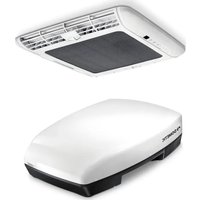
Exterior view of a black DOMETIC sensor device with ventilation slots and mounting base (no visible text or symbols beyond branding)Breathe 2500, Breathe 4500, Breathe 4500 Marine
EN
Air purifier
Installation and Operating Manual.....54
DE
Luftreiniger
© 2023 Dometic Group. The visual appearance of the contents of this manual is protected by copyright and design law. The underlying technical design and the products contained herein may be protected by design, patent or be patent pending. The trademarks mentioned in this manual belong to Dometic Sweden AB. All rights are reserved.
1
Breathe 2500
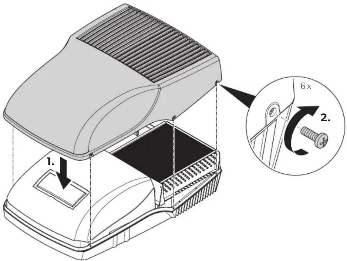
natural_image
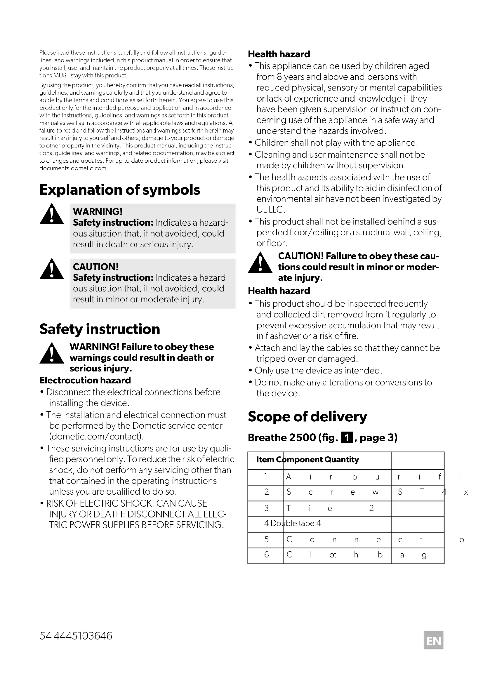
Line drawing of a mechanical device with a lid and base, showing internal components (no text or symbols)1
natural_image
Pure diagram of a rectangular panel with a textured base and curved cutouts, labeled '6' (no text or symbols beyond label)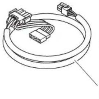
natural_image
Line drawing of a multi-pin connector with coiled cable (no text or symbols)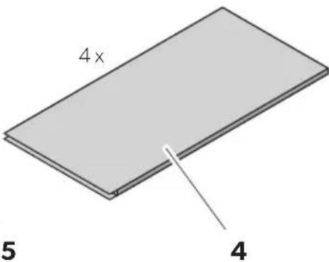
2
Breathe 4500
(Brisk II, Blizzard NTX MECH, Penguin II MECH, FreshJet Series 3 MECH, FreshJet Series 4 MECH)
Breathe 4500
(Blizzard NTX ELEC, Penguin II ELEC)
3
Breathe 4500 Marine
4
Breathe 2500 / 4500 / 4500 Marine
FreshJet (ADB2012)

natural_image
Technical illustration of a device interior showing internal components and a rising arrow (no text or symbols)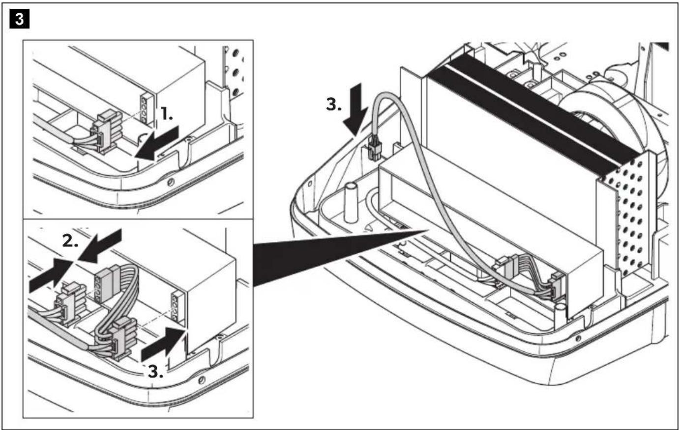
natural_image
Technical diagram of an open computer case with internal components and a downward arrow indicating a component (no text or symbols present)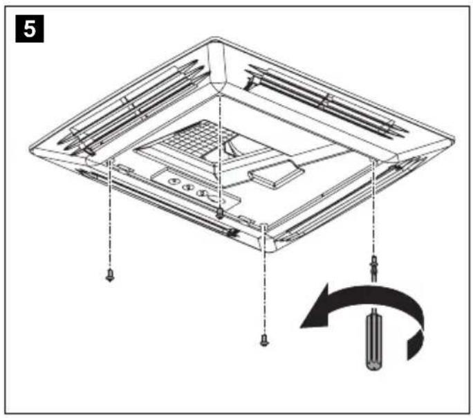
natural_image
Technical diagram of a device with labeled parts and a circular arrow indicating rotation (no text or symbols present)
natural_image
Technical diagram of a mechanical assembly with labeled components and directional arrows (no text or symbols)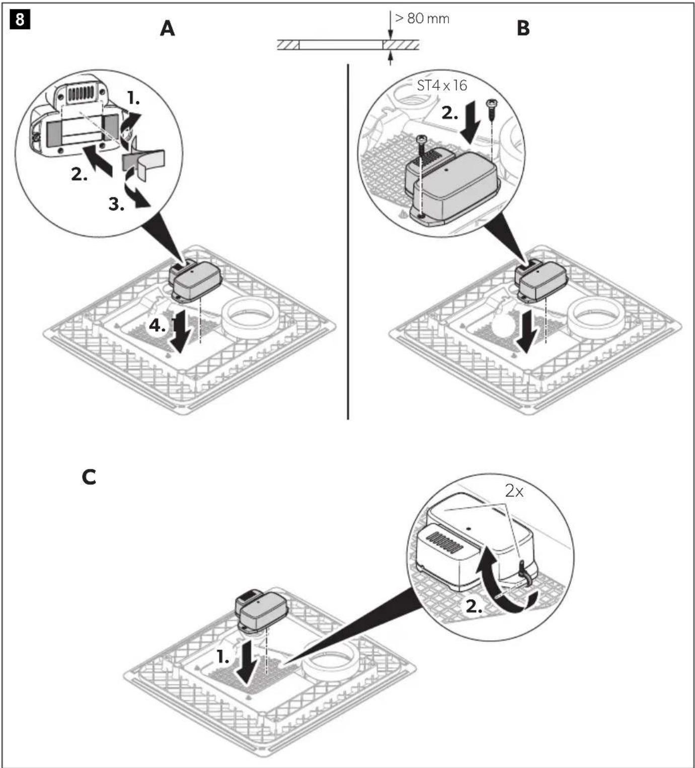

natural_image
Technical line drawing of a mechanical component with a connector and grid base, no visible text or symbols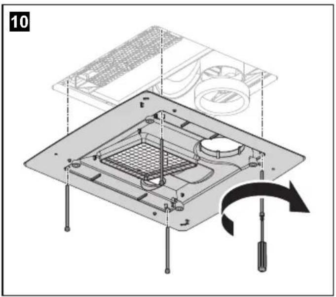
natural_image
Isometric diagram of a computer chassis with visible internal components and a black arrow indicating a specific area (no text or symbols)15

natural_image
Technical line drawing of an open electronic device with internal components and a downward arrow indicating a component (no text or symbols present)16
FreshJet (ADB2015)
natural_image
Technical illustration of a device interior showing internal components and a rising arrow (no text or symbols)3
4
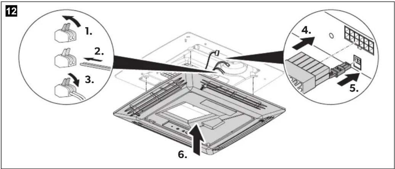
natural_image
Technical line drawing of an open electronic device casing with a black arrow indicating a downward force or component (no text or symbols present)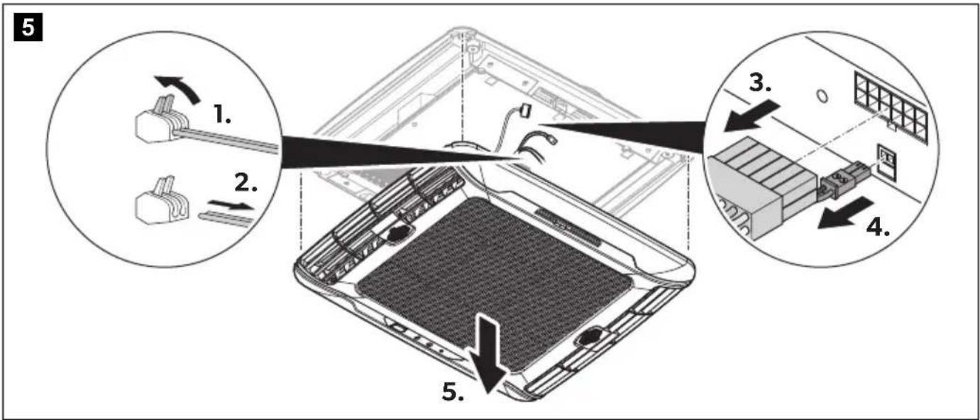
natural_image
Technical diagram of a mechanical device inside a grid-patterned enclosure, showing internal components and wiring (no text or symbols)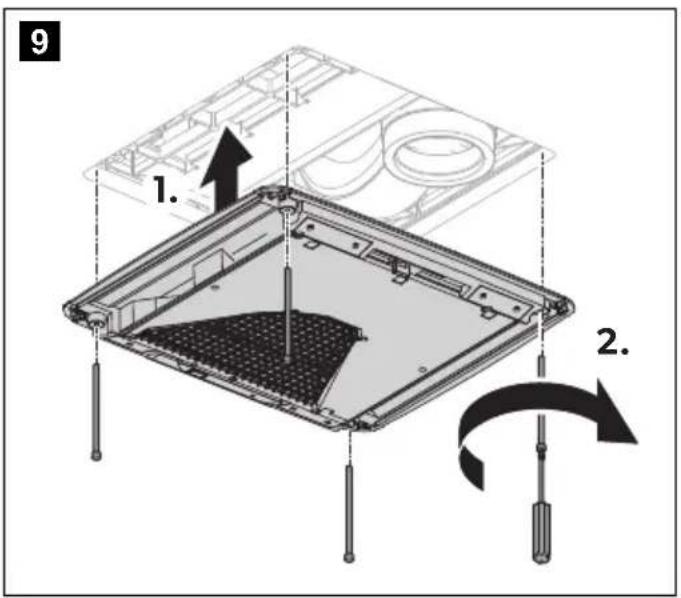
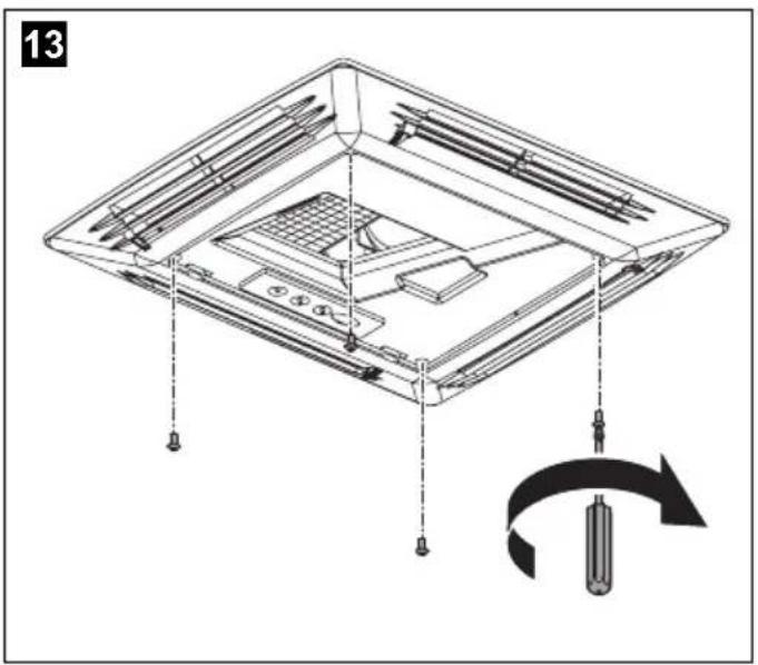
13
natural_image
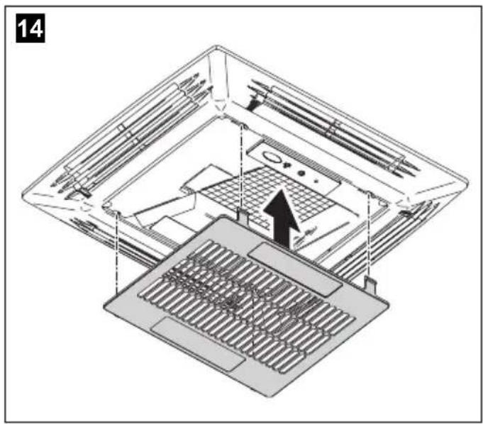
Technical line drawing of an open electronic device with internal components and a downward arrow indicating a component (no text or symbols present)14

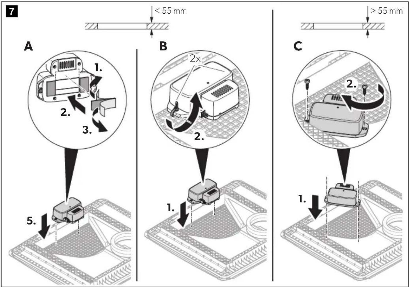
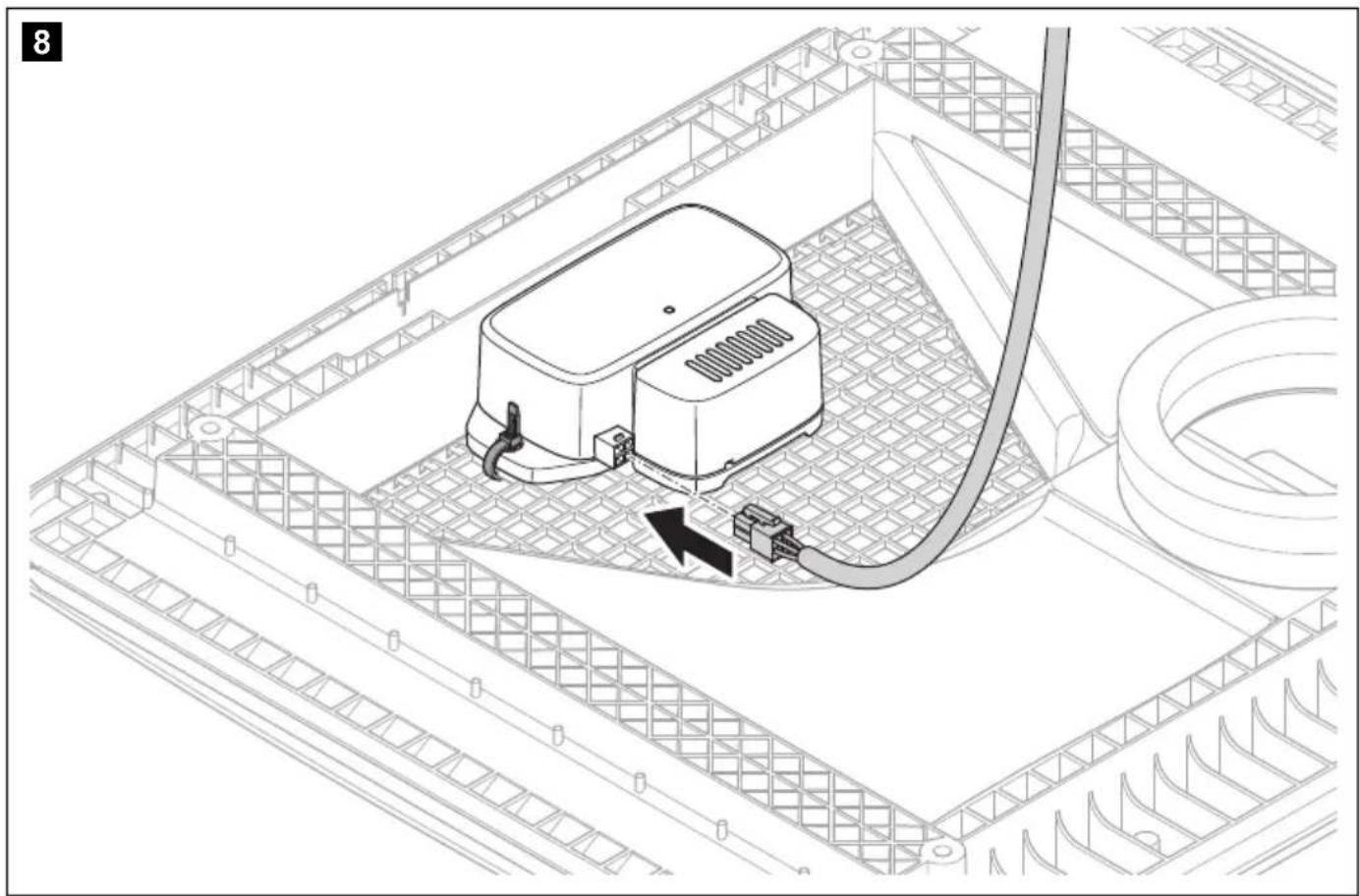
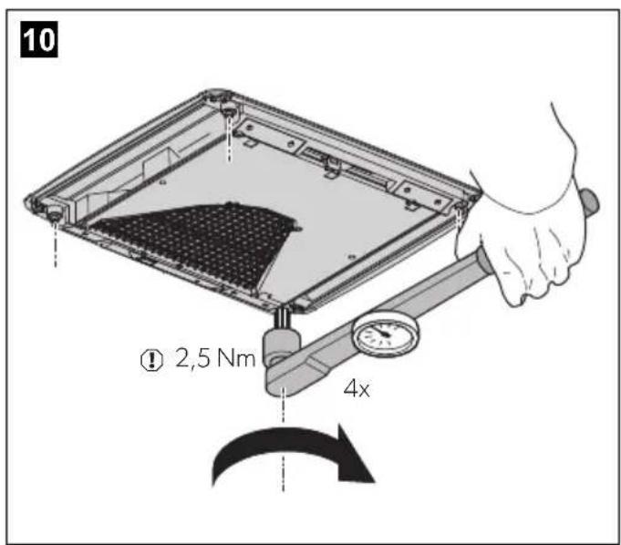
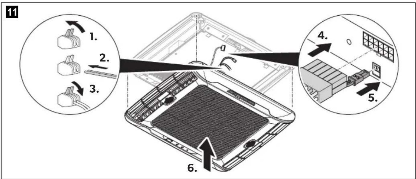
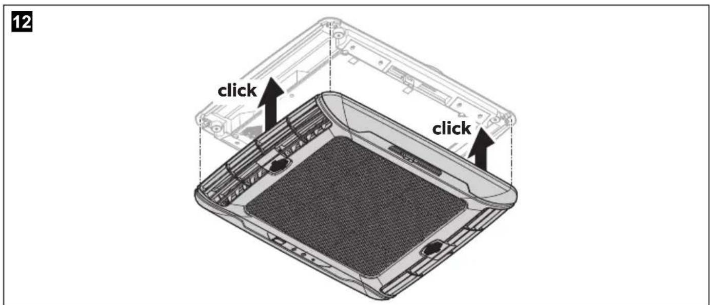
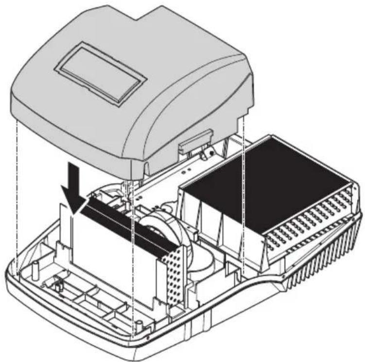
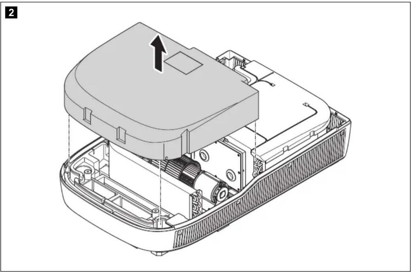
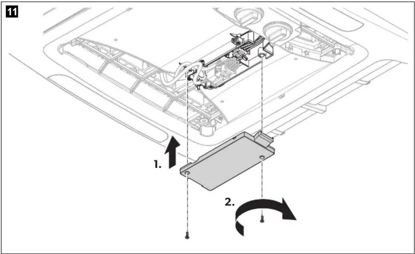
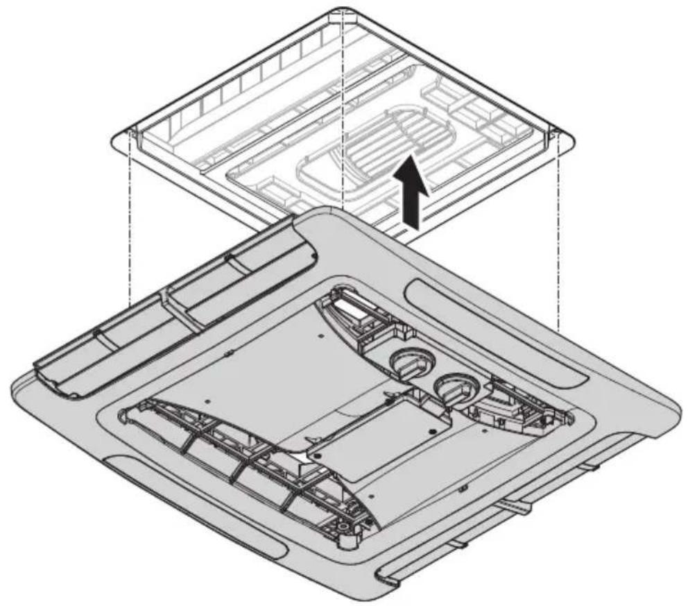
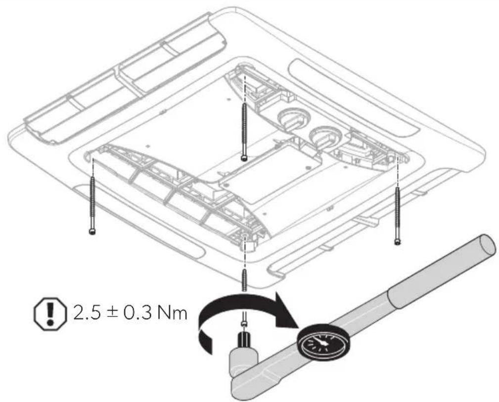
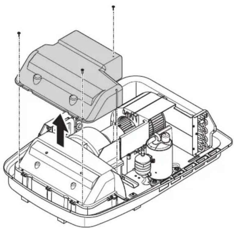
FreshJet Series 3 MECH, FreshJet Series 4 MECH
natural_image
Technical illustration of an open electronic device casing with internal components and a directional arrow indicating motion (no text or symbols present)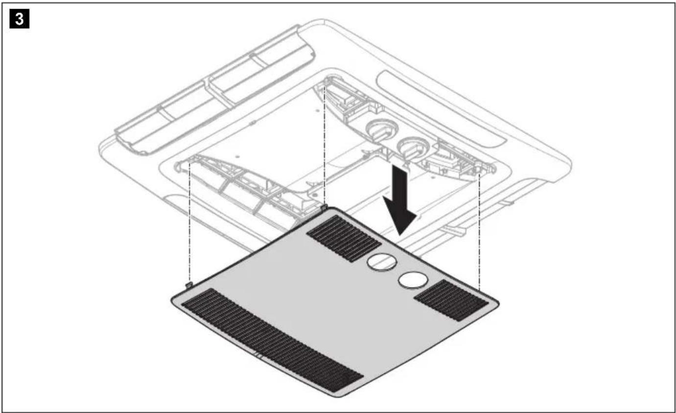
natural_image
Diagram of a laptop chassis showing internal components and a base panel with heat sinks (no text or symbols)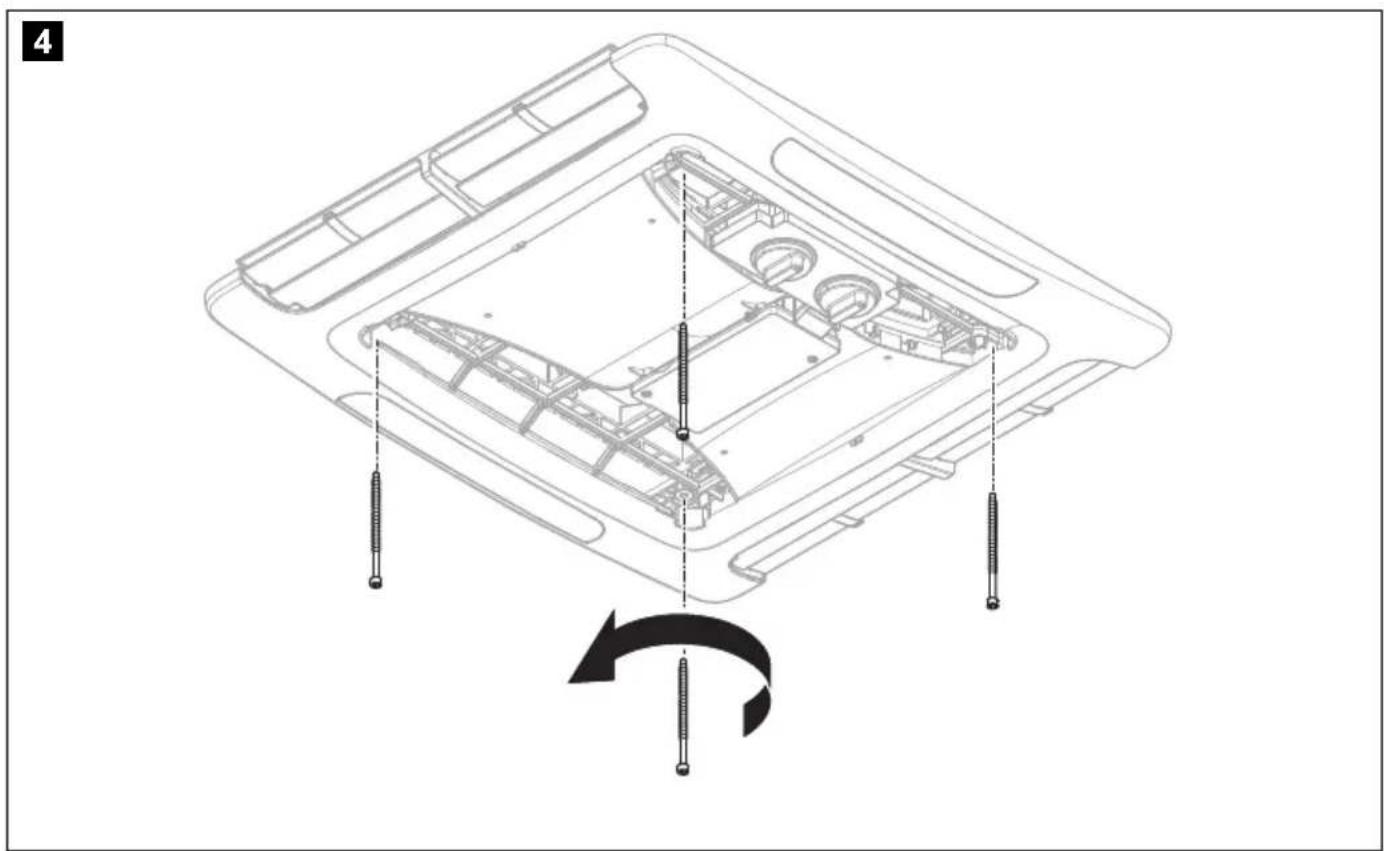
natural_image
Technical line drawing of a device's internal components with screw fasteners, showing assembly and rotation (no text or symbols)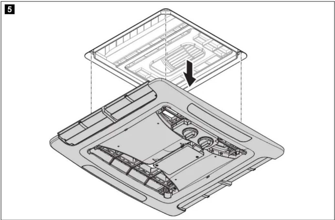
natural_image
Technical diagram of a device's internal structure showing top and side views with no visible text or symbols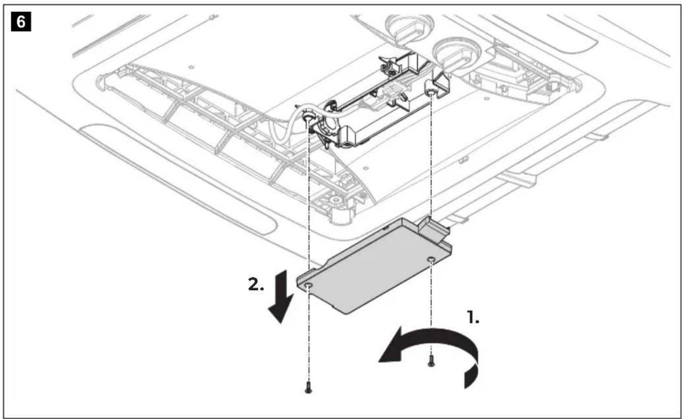
natural_image
Technical line drawing of a mechanical assembly with a worker and curved pipe (no text or symbols)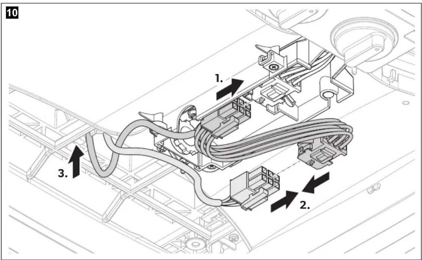

13
natural_image
Technical line drawing of a device interior showing internal components and a highlighted top section (no text or symbols)14
15
1
2
natural_image
Technical line drawing of an internal combustion engine assembly (no text or labels)3

natural_image
Technical line drawing of an internal mechanical assembly with no visible text or symbols4


1

2
natural_image
Technical line drawing of an internal combustion engine housing with cooling fans and air ducts (no text or labels)3
natural_image
Technical line drawing of an internal mechanical assembly with no visible text or symbols4

1

2

natural_image
Technical line drawing of a mechanical assembly inside a container, showing internal components and a top component (no text or symbols)
7
8

1
2
natural_image
Technical line drawing of a mechanical assembly inside a container, showing internal components and a top component (no text or symbols)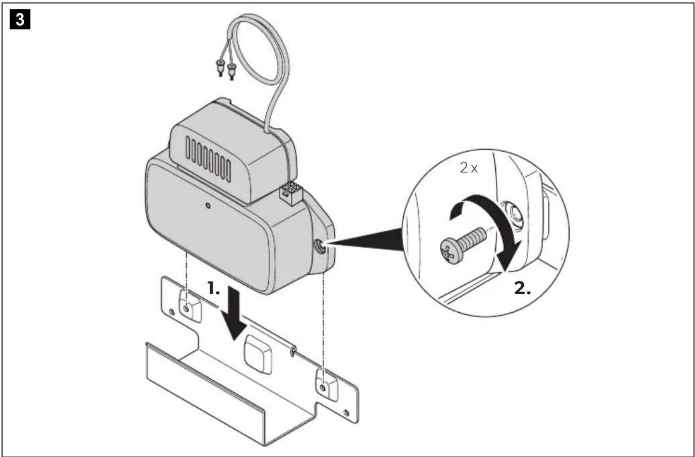

Brisk II
1
2
natural_image
Technical line drawing of a mechanical assembly with internal components and a directional arrow (no text or symbols)
7
8
natural_image
Technical line drawing of a camera mounted on a wall, showing cable and connector (no text or symbols)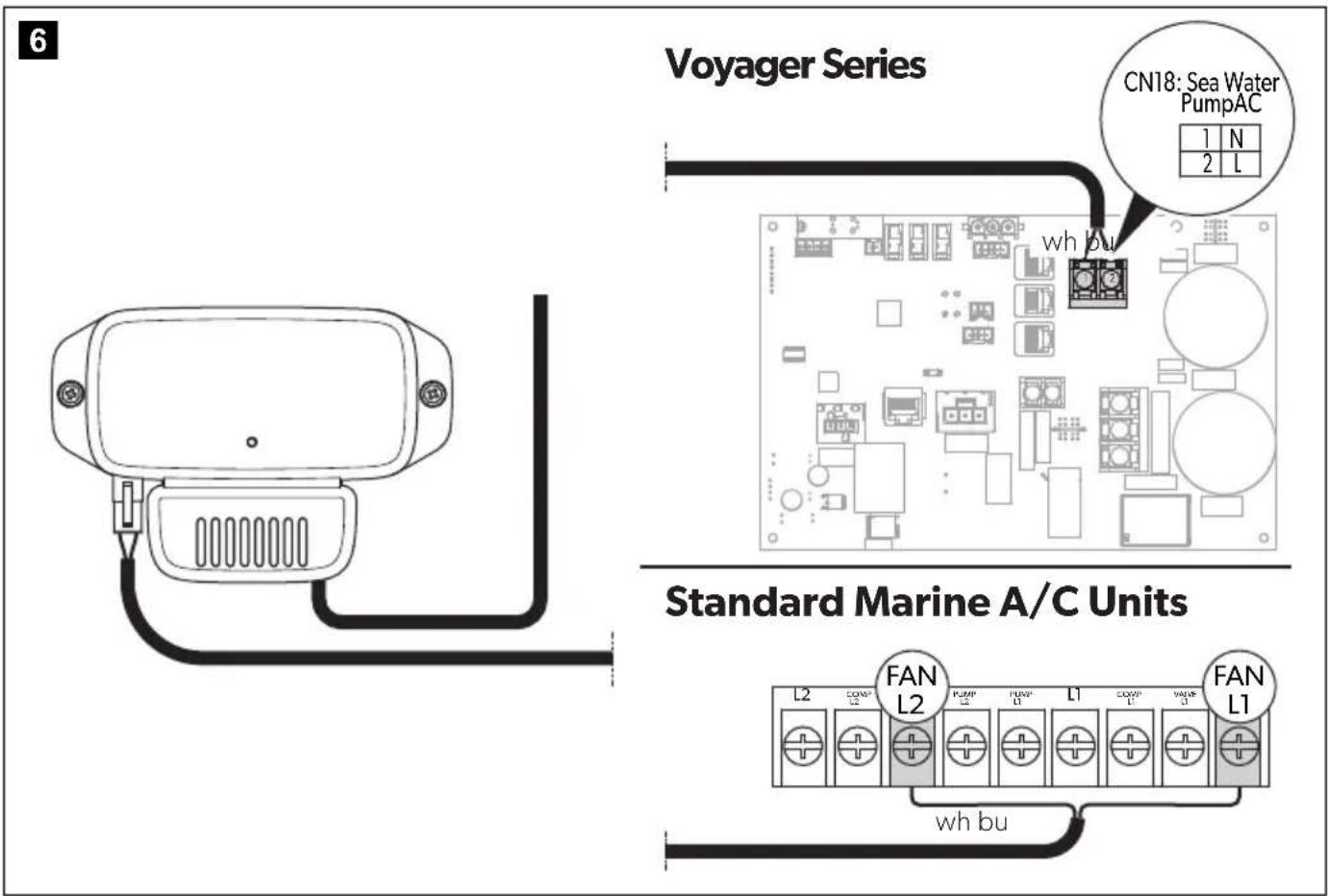
Please read these instructions carefully and follow all instructions, guidelines, and warnings included in this product manual in order to ensure that you install, use, and maintain the product properly at all times. These instructions MUST stay with this product.
By using the product, you hereby confirm that you have read all instructions, guidelines, and warnings carefully and that you understand and agree to abide by the terms and conditions as set forth herein. You agree to use this product only for the intended purpose and application and in accordance with the instructions, guidelines, and warnings as set forth in this product manual as well as in accordance with all applicable laws and regulations. A failure to read and follow the instructions and warnings set forth herein may result in an injury to yourself and others, damage to your product or damage to other property in the vicinity. This product manual, including the instructions, guidelines, and warnings, and related documentation, may be subject to changes and updates. For up-to-date product information, please visit documents.dometic.com.
Explanation of symbols

WARNING!
Safety instruction: Indicates a hazardous situation that, if not avoided, could result in death or serious injury.

CAUTION!
Safety instruction: Indicates a hazardous situation that, if not avoided, could result in minor or moderate injury.
Safety instruction

WARNING! Failure to obey these warnings could result in death or serious injury.
Electrocution hazard
- Disconnect the electrical connections before installing the device.
- The installation and electrical connection must be performed by the Dometic service center (dometic.com/contact).
- These servicing instructions are for use by qualified personnel only. To reduce the risk of electric shock, do not perform any servicing other than that contained in the operating instructions unless you are qualified to do so.
- RISK OF ELECTRIC SHOCK. CAN CAUSE INJURY OR DEATH: DISCONNECT ALL ELECTRIC POWER SUPPLIES BEFORE SERVICING.
Health hazard
- This appliance can be used by children aged from 8 years and above and persons with reduced physical, sensory or mental capabilities or lack of experience and knowledge if they have been given supervision or instruction concerning use of the appliance in a safe way and understand the hazards involved.
• Children shall not play with the appliance. - Cleaning and user maintenance shall not be made by children without supervision.
- The health aspects associated with the use of this product and its ability to aid in disinfection of environmental air have not been investigated by UL LLC.
- This product shall not be installed behind a suspended floor/ceiling or a structural wall, ceiling, or floor.

CAUTION! Failure to obey these cau-tions could result in minor or moderate injury.
Health hazard
- This product should be inspected frequently and collected dirt removed from it regularly to prevent excessive accumulation that may result in flashover or a risk of fire.
- Attach and lay the cables so that they cannot be tripped over or damaged.
- Only use the device as intended.
- Do not make any alterations or conversions to the device.
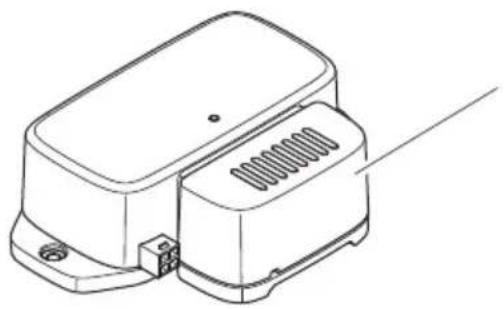
Scope of delivery
Breathe 2500 (fig. 1, page 3)
| Item Component Quantity | ||||||||
| 1 | A | i | r | p | u | r | i | f |
| 2 | S | c | r | e | w | S | T | 4 |
| 3 | T | i | e | 2 | ||||
| 4 Double tape 4 | ||||||||
| 5 | C | o | n | n | e | c | t | i |
| 6 | C | l | ot | h | b | a | g | |
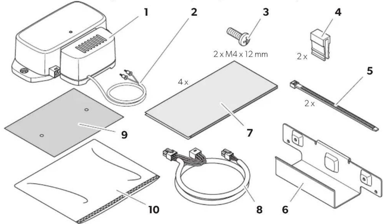
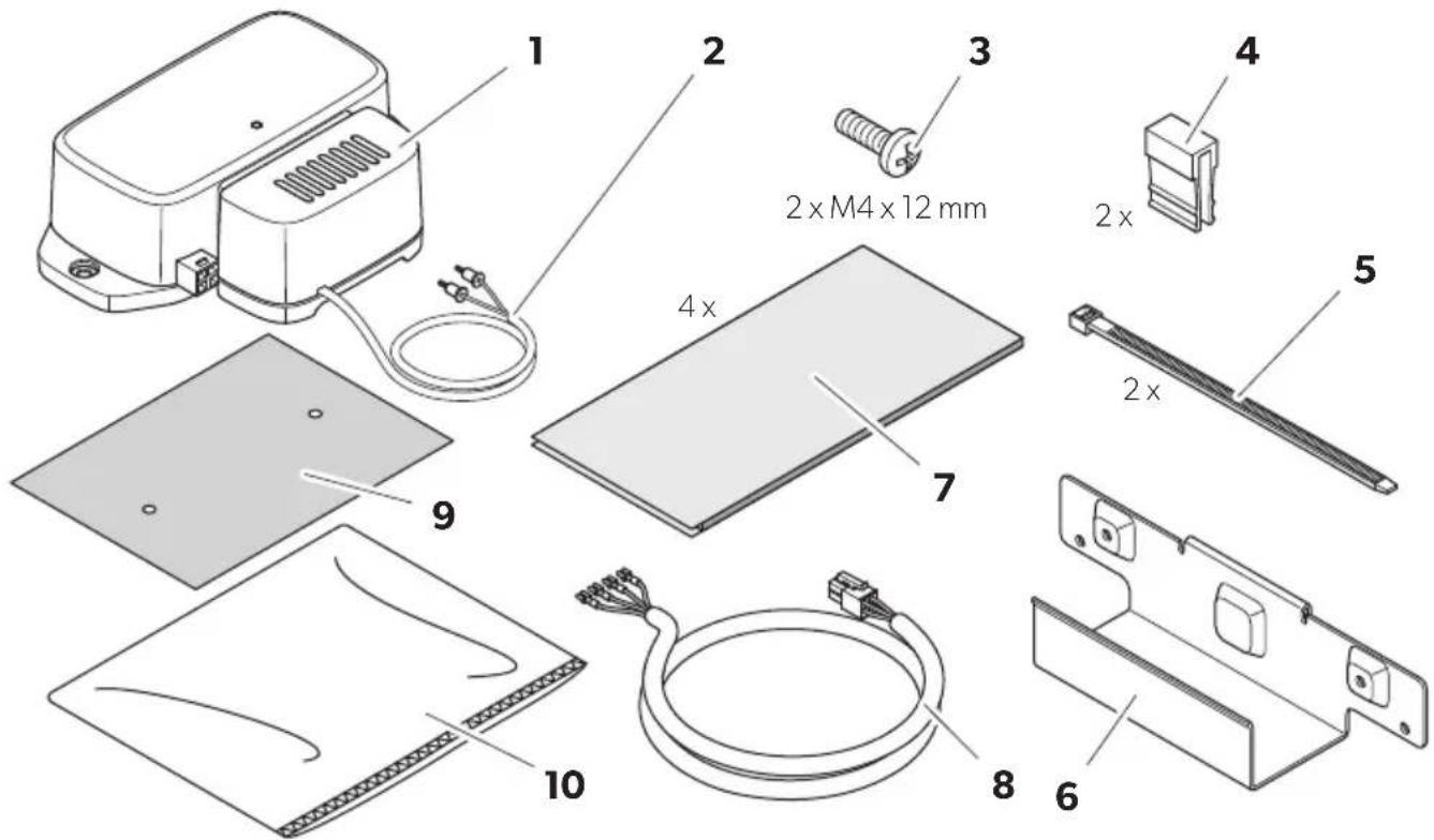
Breathe 4500 (fig. 2, page 4)
| Item Component Quantity | ||
| 1 | A i r p u | r i f |
| 2 Cable with 2 ionization needles | 1 | |
| 3 | S c r e w | M 4 |
| 4 Clip 2 | ||
| 5 | T i e | |
| 6 | S u p p o | r t |
| 7 Double tape | 4 | |
| 8 Connection cable 2 | ||
| 9 Drill template | 1 | |
| 10 | Cloth bag | 1 |
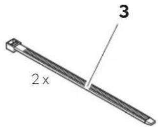
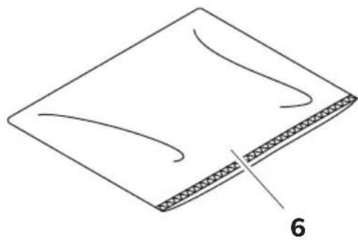
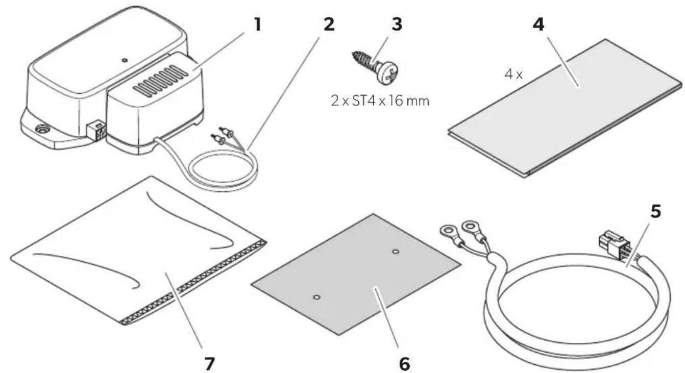
Breathe 4500 Marine (fig. 3, page 5)
| Item Component Quantity | ||
| 1 | A i r p u | r i f |
| 2 Cable with 2 ionization needles | 1 | |
| 3 | S c r e w | S T4 |
| 4 Double tape | 4 | |
| 5 Connection cable | 1 | |
| 6 Drill template | 1 | |
| 7 | C l o t h | b a g |
Intended use
The air purifier is intended to be installed to an air conditioner. The air purifier is intended to clean the air and to reduce mold, dust, odors, and particles.
The air purifier can be installed on RV and Marine A/C units.
The air purifier is suitable for:
• Dometic RV and Marine air conditioners
The air purifier is not suitable for:
- Ventilators
- Spaces in contact with water
This product is only suitable for the intended purpose and application in accordance with these instructions.
This manual provides information that is necessary for proper installation and/or operation of the product. Poor installation and/or improper operating or maintenance will result in unsatisfactory performance and a possible failure.
The manufacturer accepts no liability for any injury or damage to the product resulting from:
- Incorrect assembly or connection, including excess voltage
2• Incorrect maintenance or use of spare parts other than original spare parts provided by the manufacturer
• Alterations to the product without express permission from the manufacturer - Use for purposes other than those described in this manual
Dometic reserves the right to change product appearance and product specifications.
Technical description
The air purifier cleans the air and reduces mold, dust, odors, particles, and bacteria. For this purpose the air purifier uses needle point ionization to create both negative and positive ions that purify the air. The purified air is carried through the ductwork and out into the conditioned space.
The status LED shows whether the air purifier is working or not: 1
• LED is lit: The device is working.
• LED is off: The device is not working.
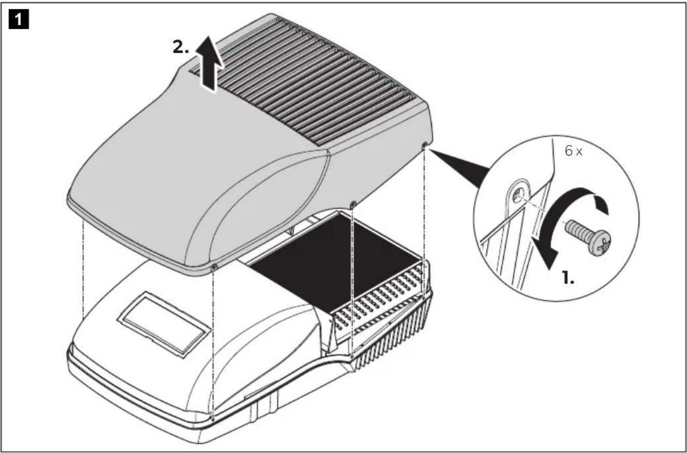
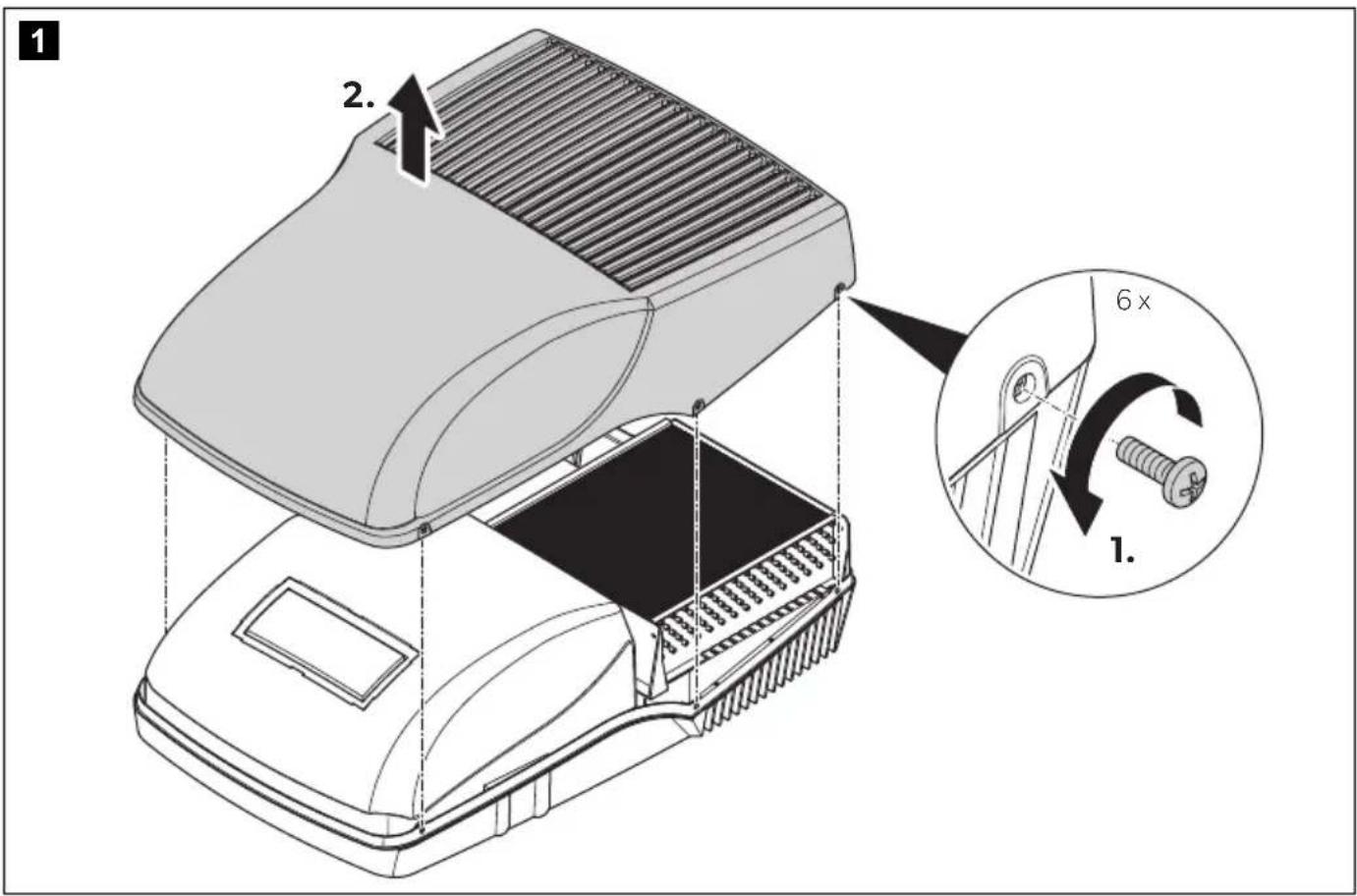
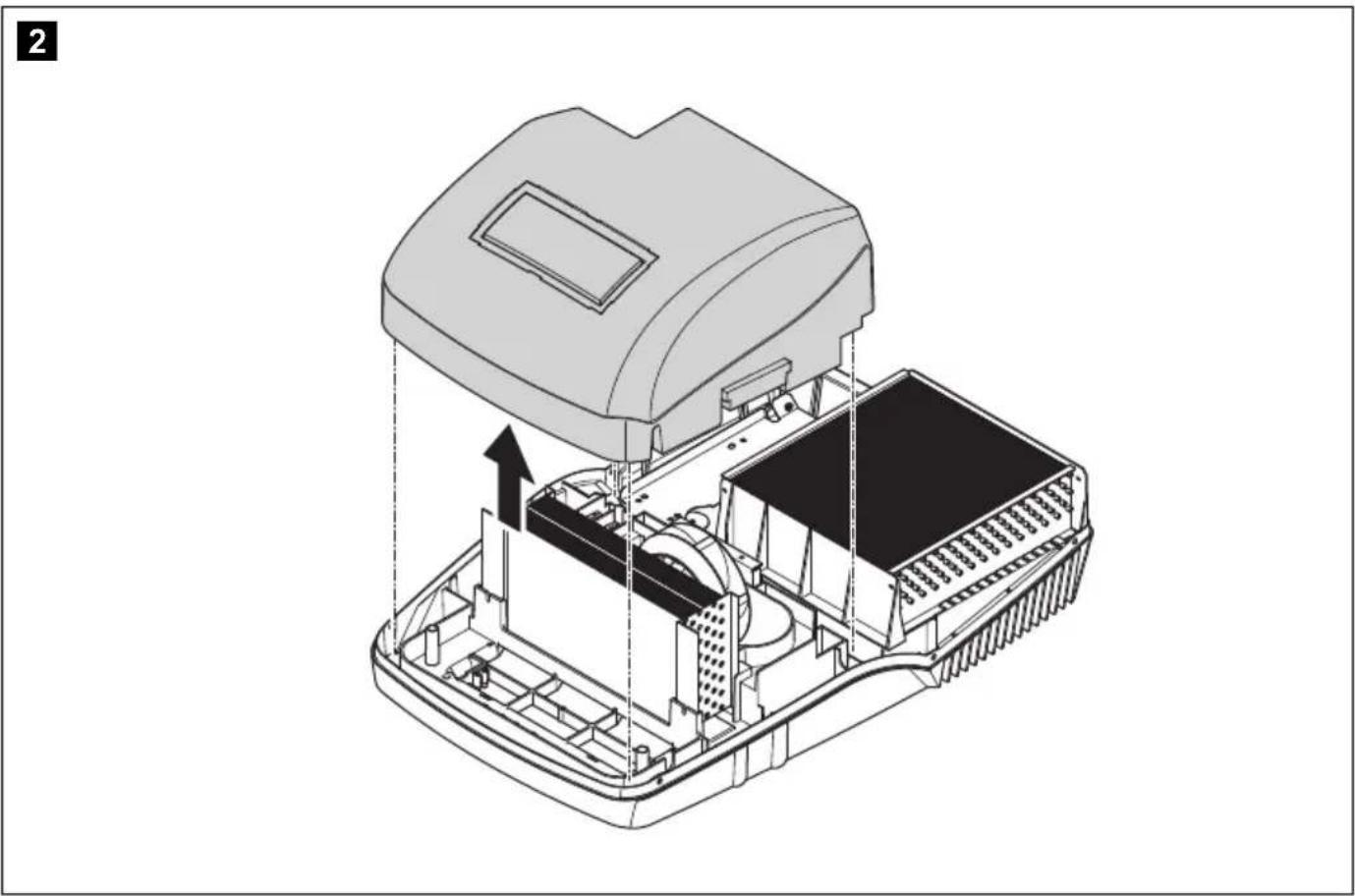
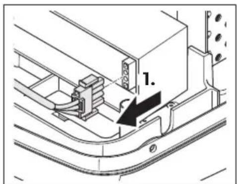
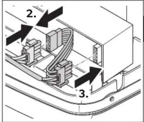
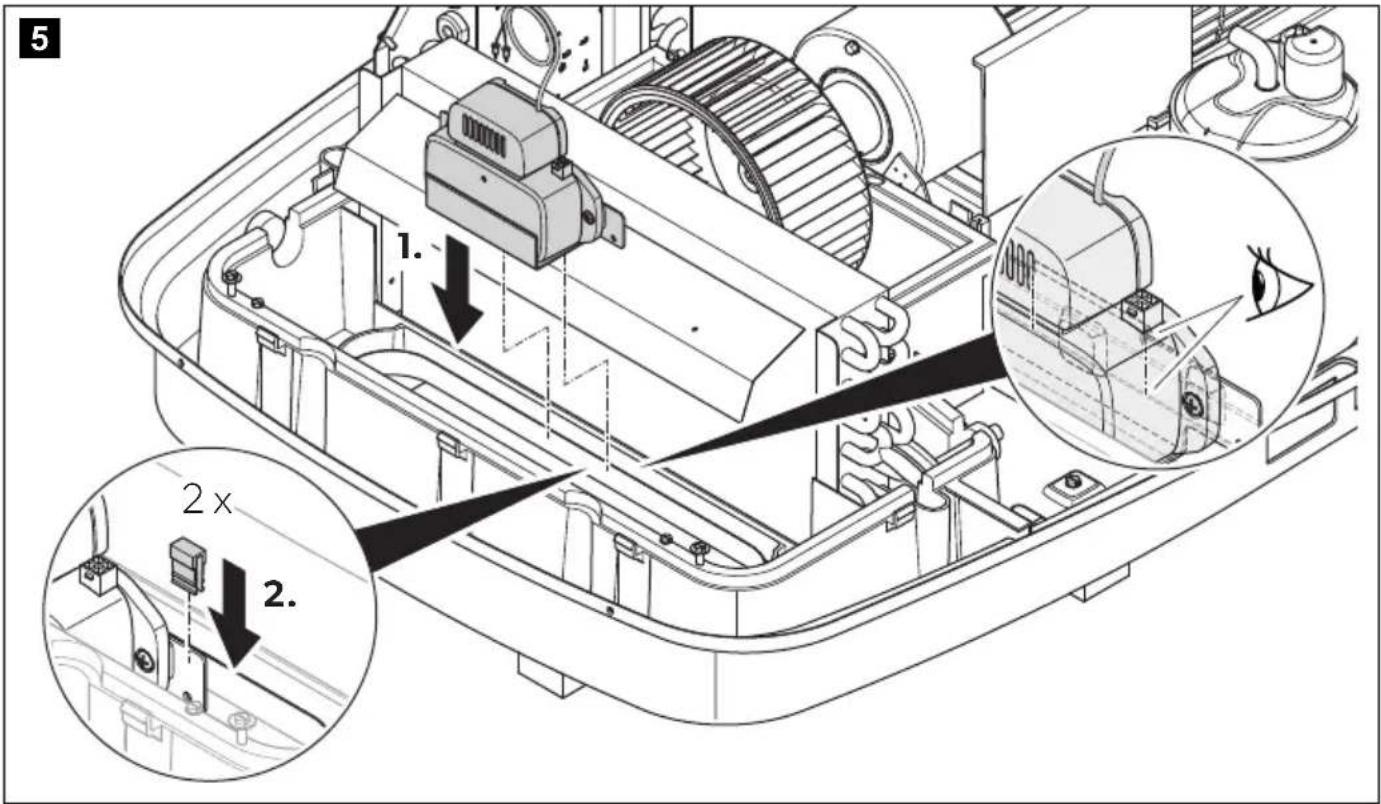
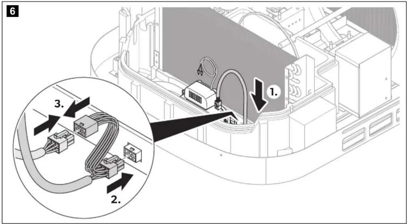
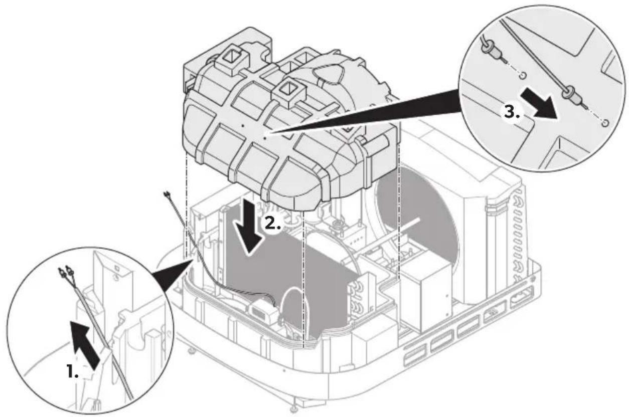
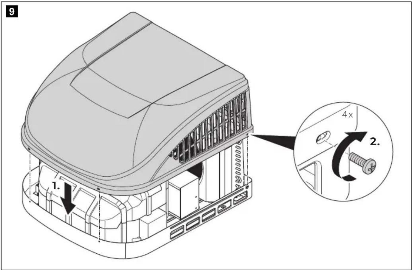
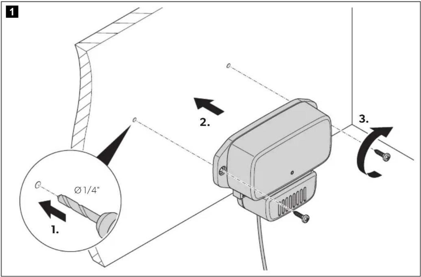
Installation

WARNING! Electric hazard
Disconnect the electrical connections before installing the device.

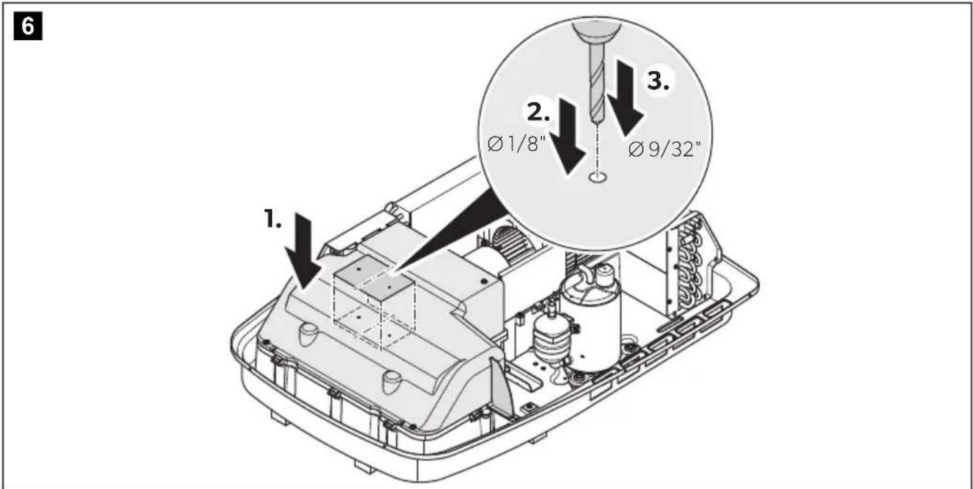
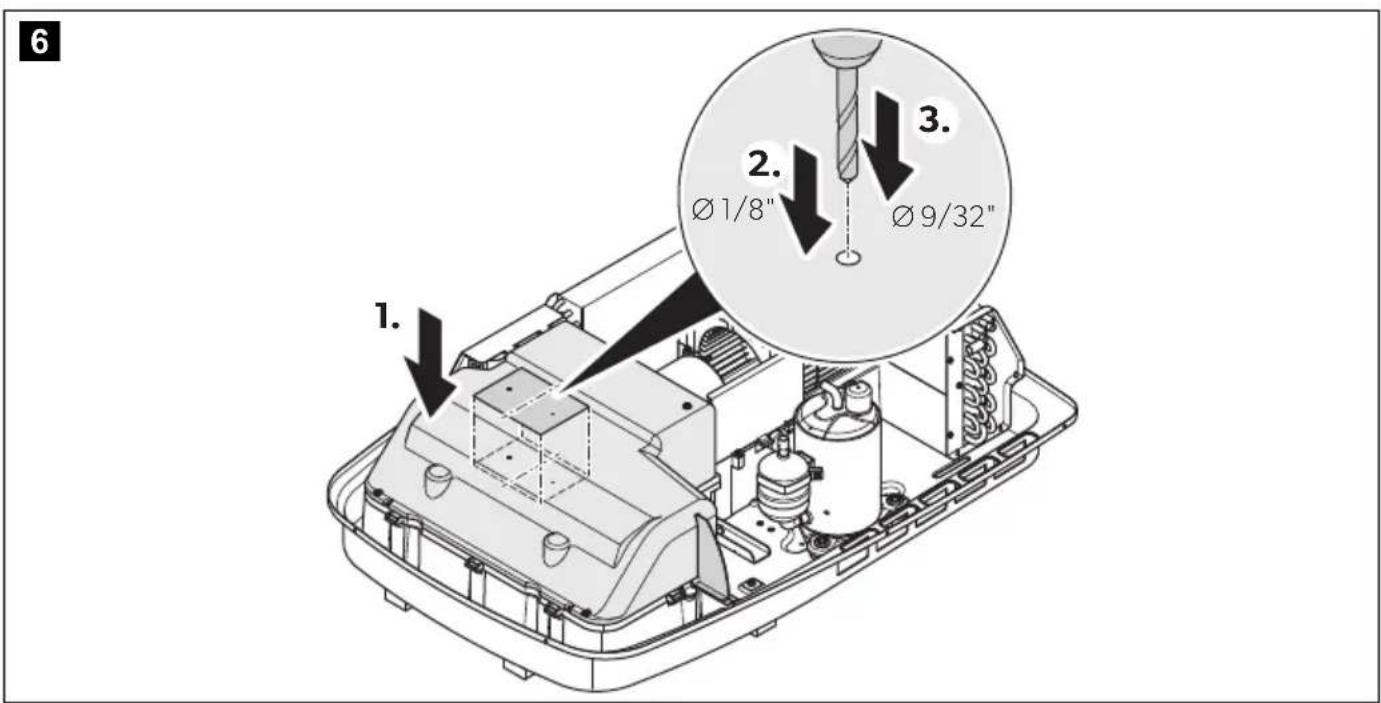
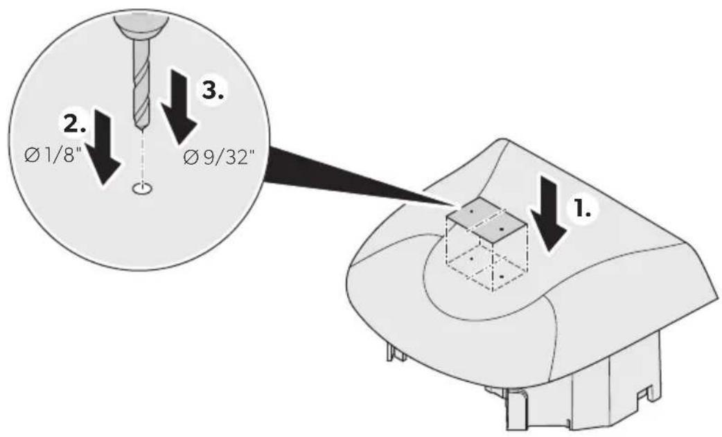
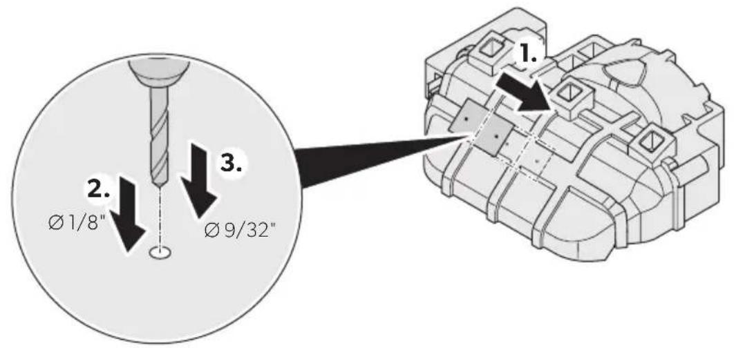
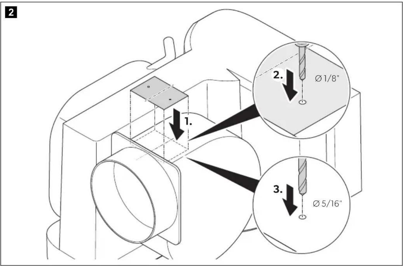
NOTICE! Damage hazard Breathe 4500, Breathe 4500
Marine only: Use the drill template included in the scope of supply to drill the holes for the ionization needles.
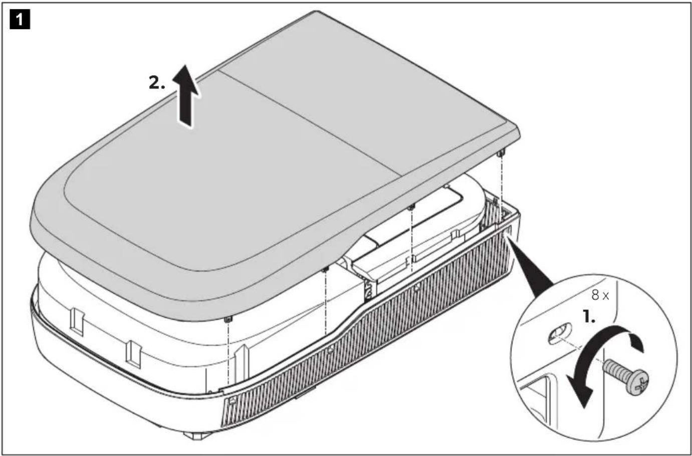
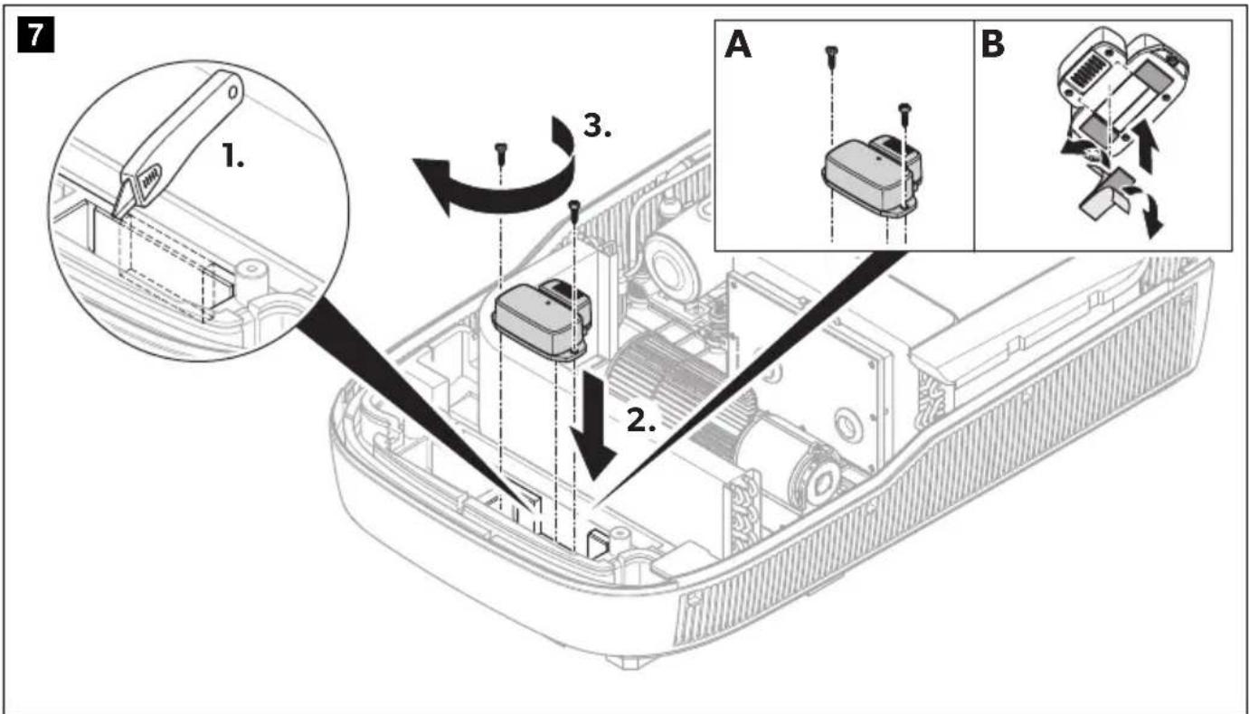
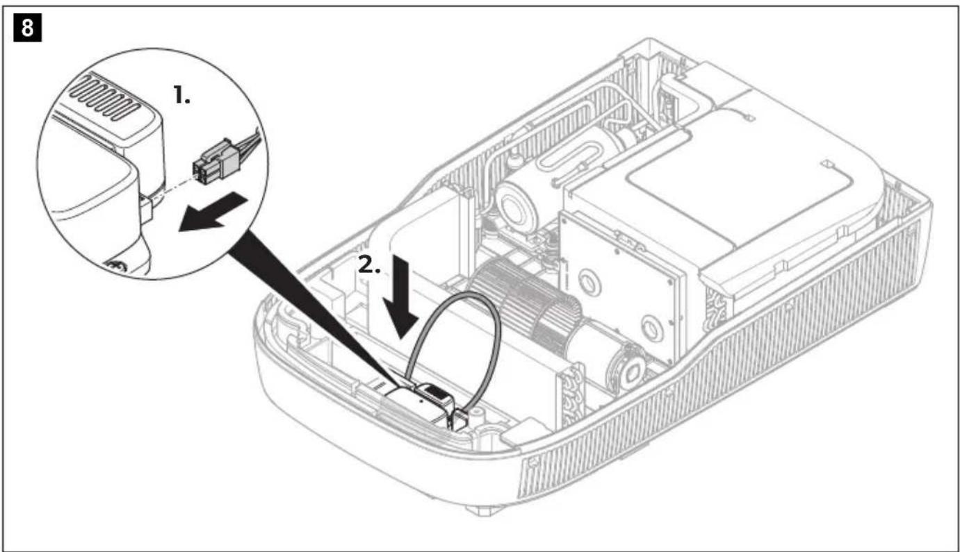
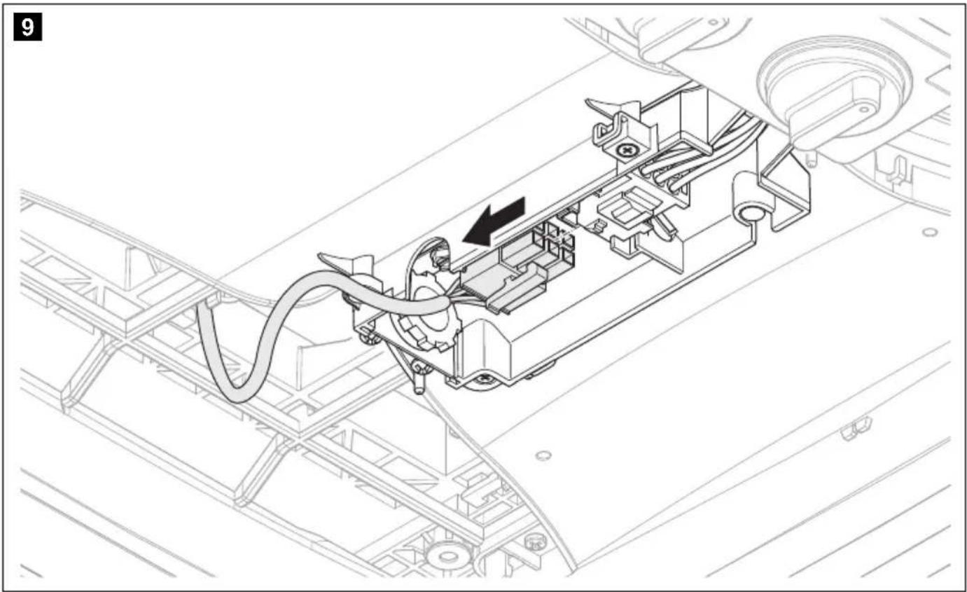
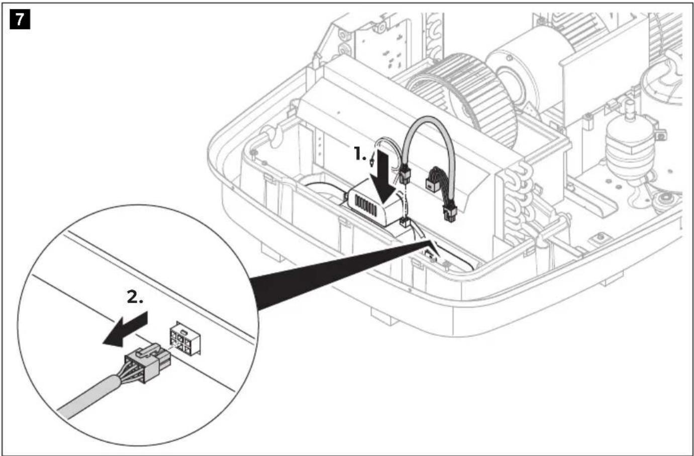
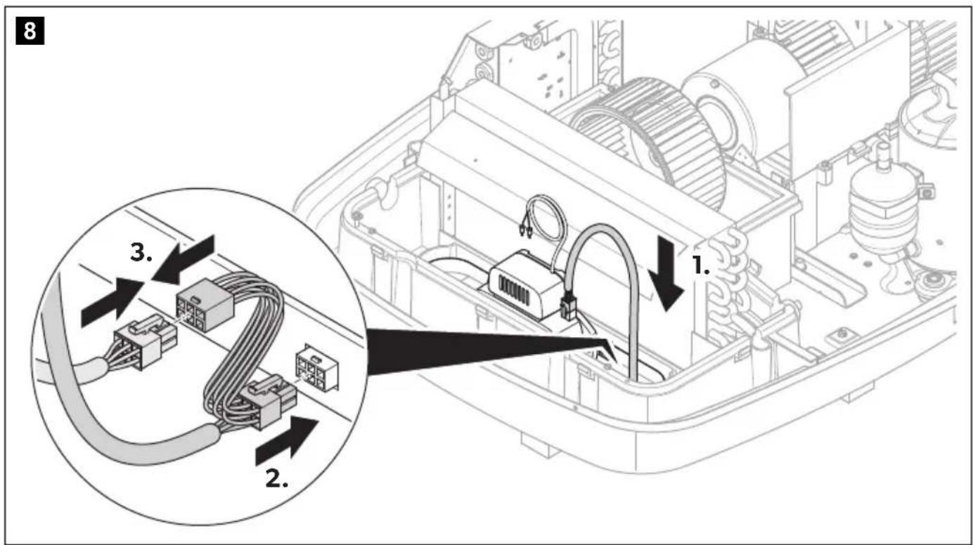
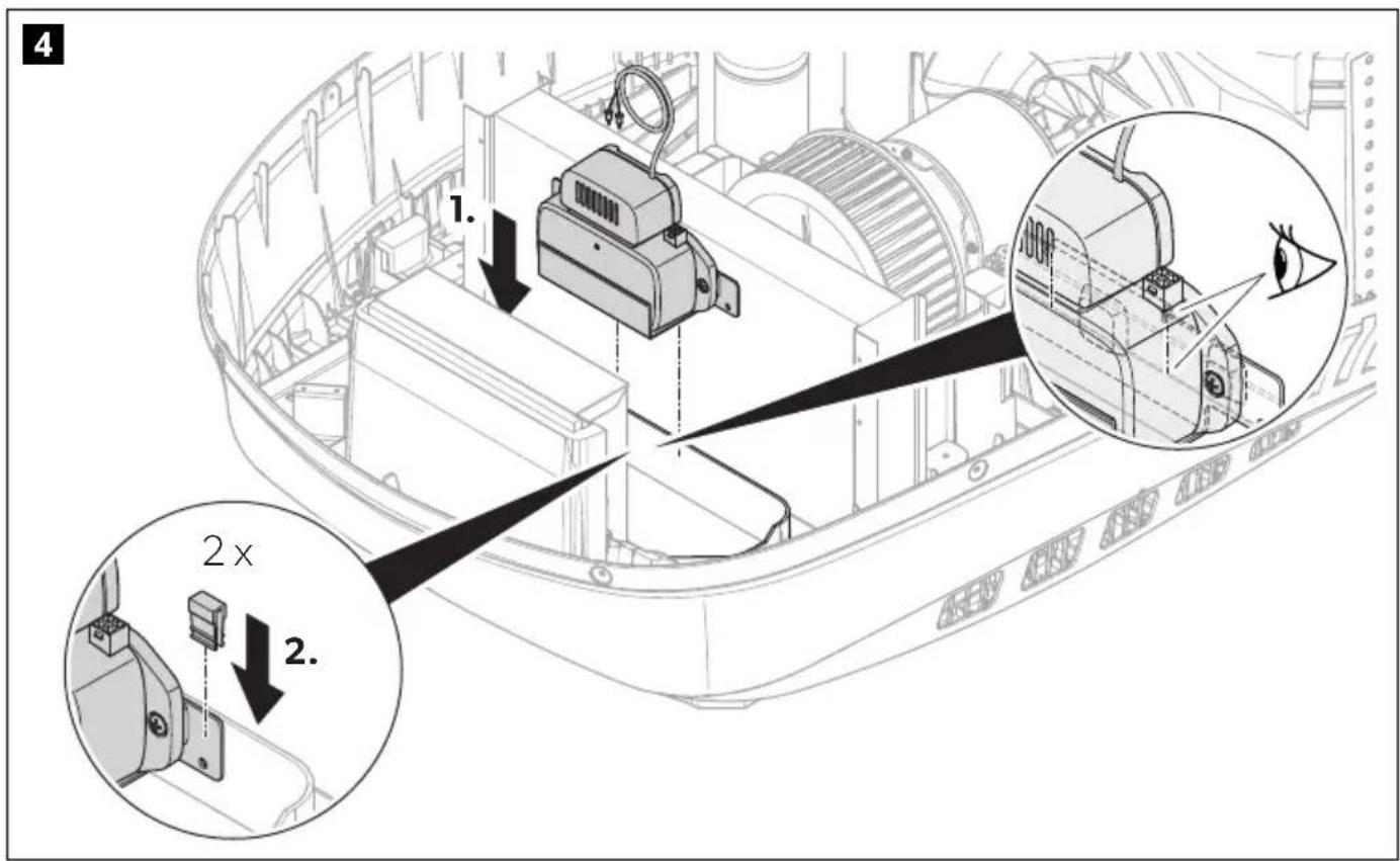
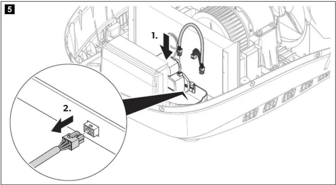
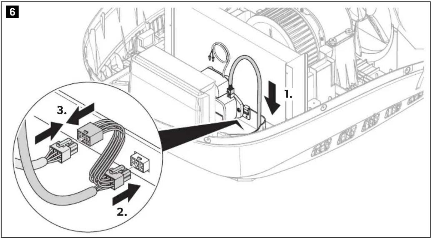
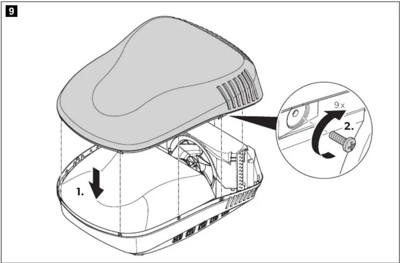
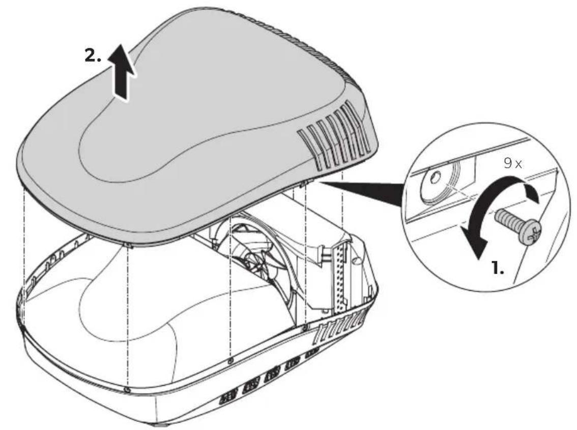
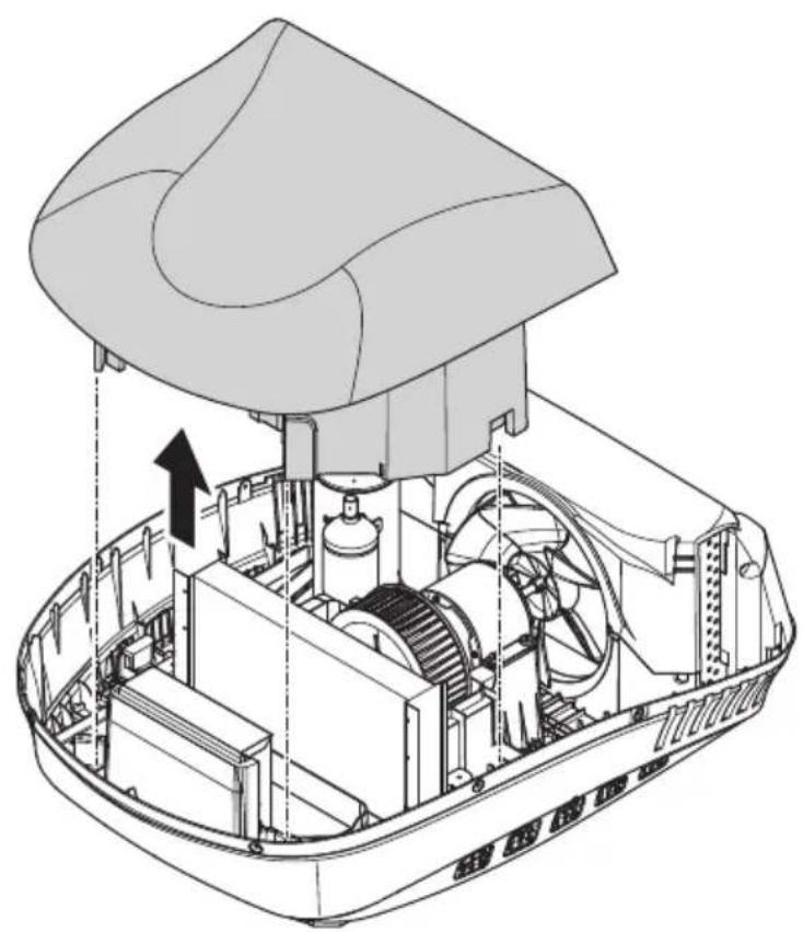
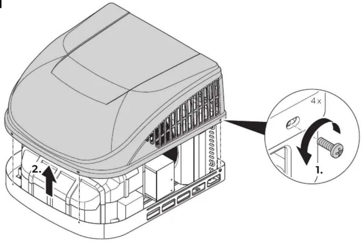
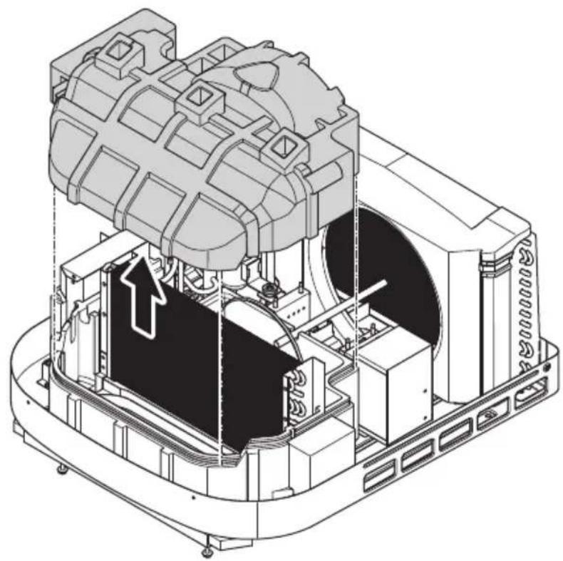
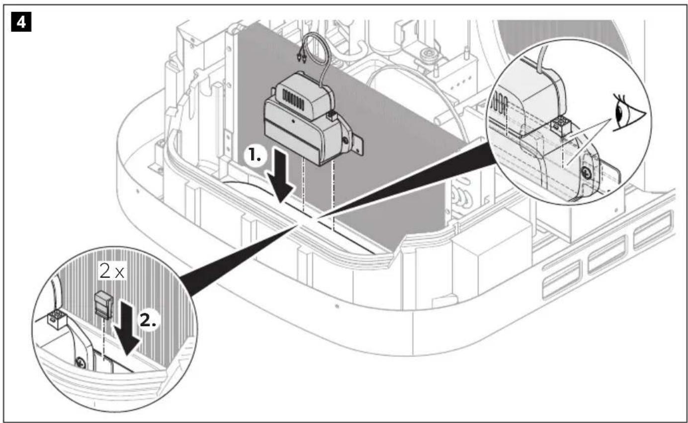
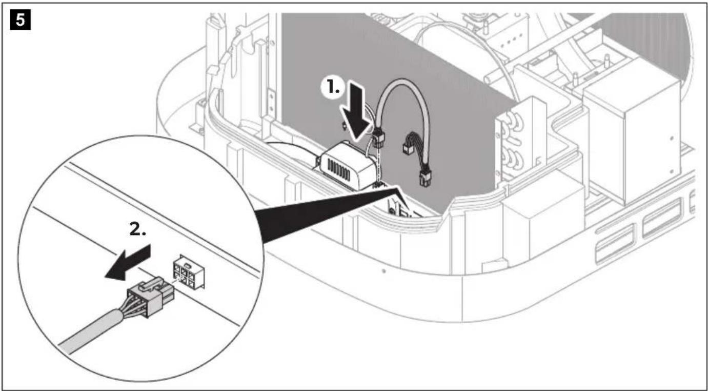
FreshJet (ADB 2012)
▶Proceed as shown in chapter "FreshJet (ADB2012)" on page 6.
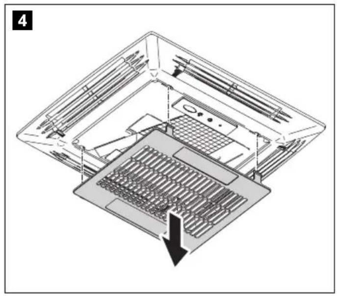
FreshJet (ADB 2015)
▶Proceed as shown in chapter "FreshJet (ADB2015)" on page 13.
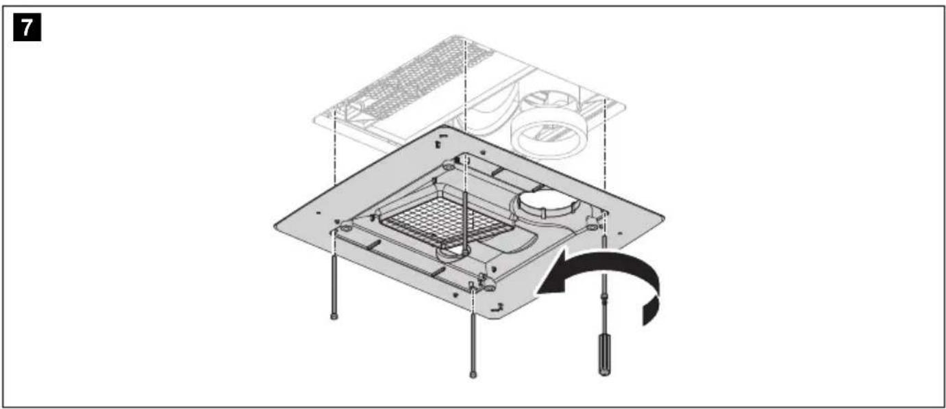
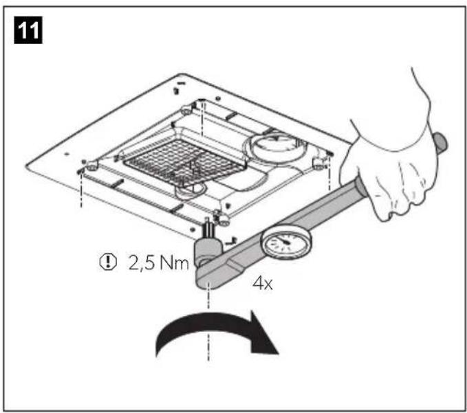
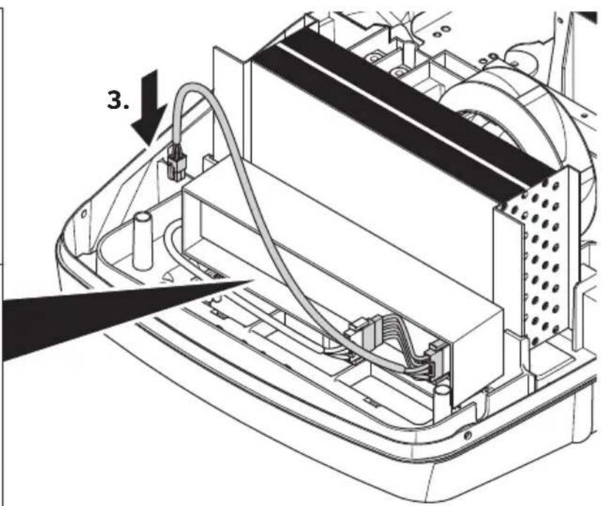
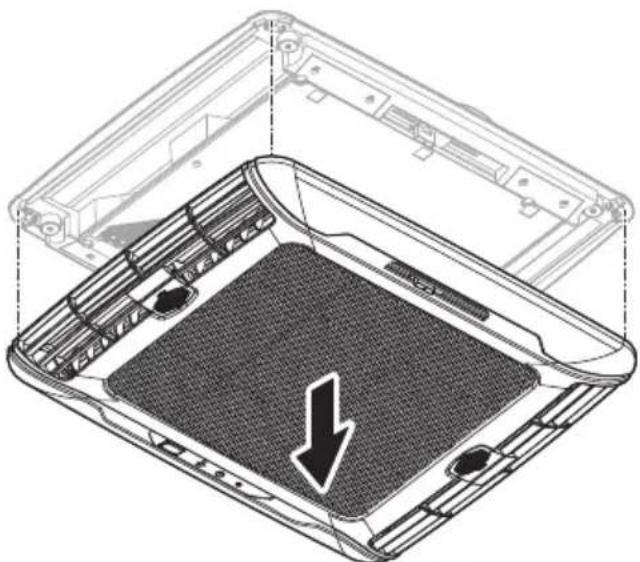
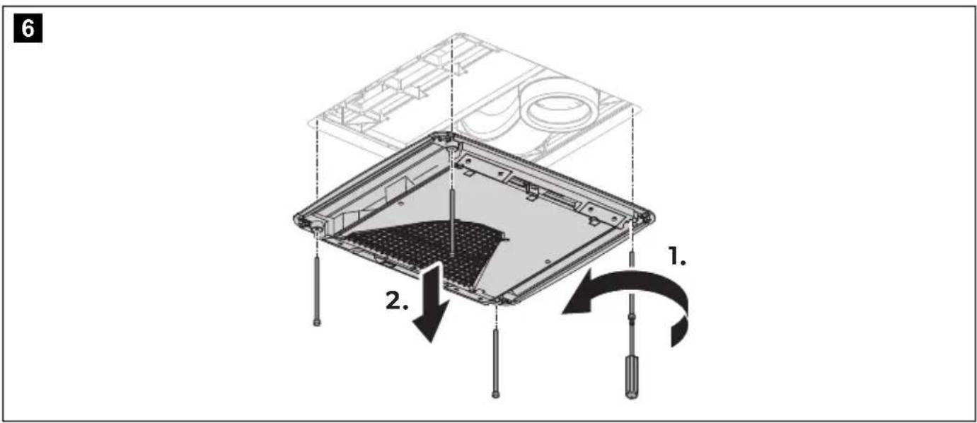
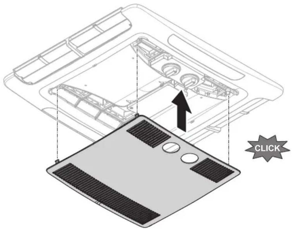
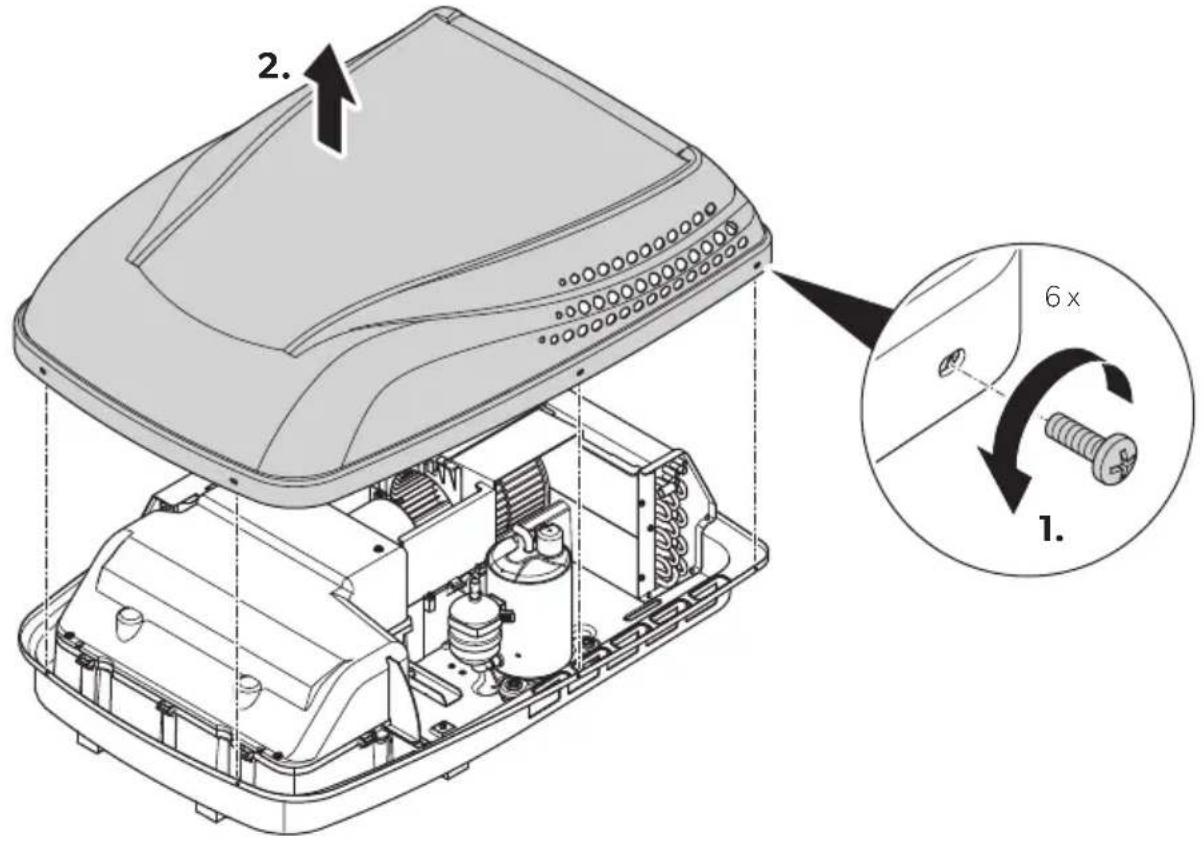
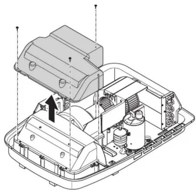
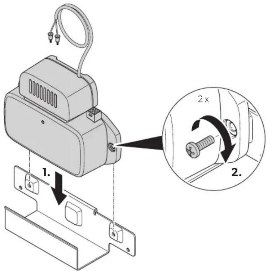
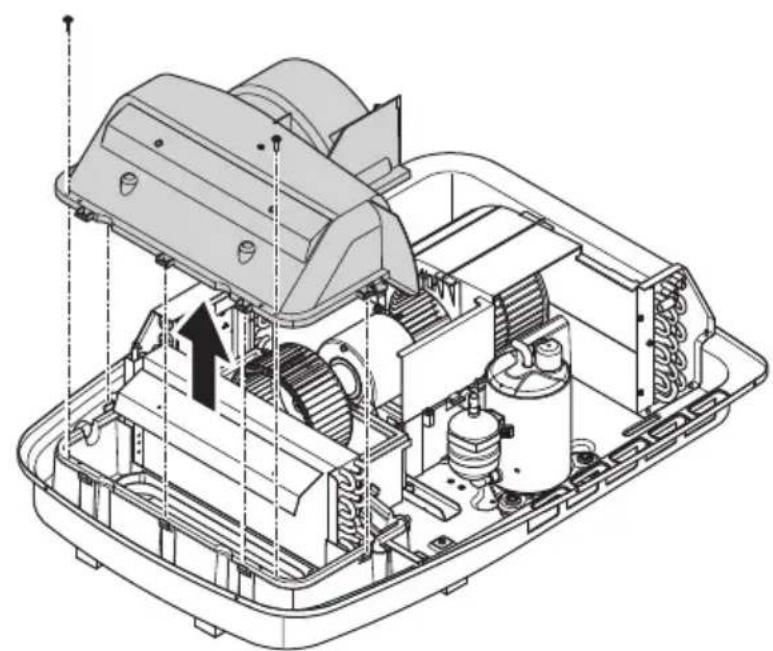
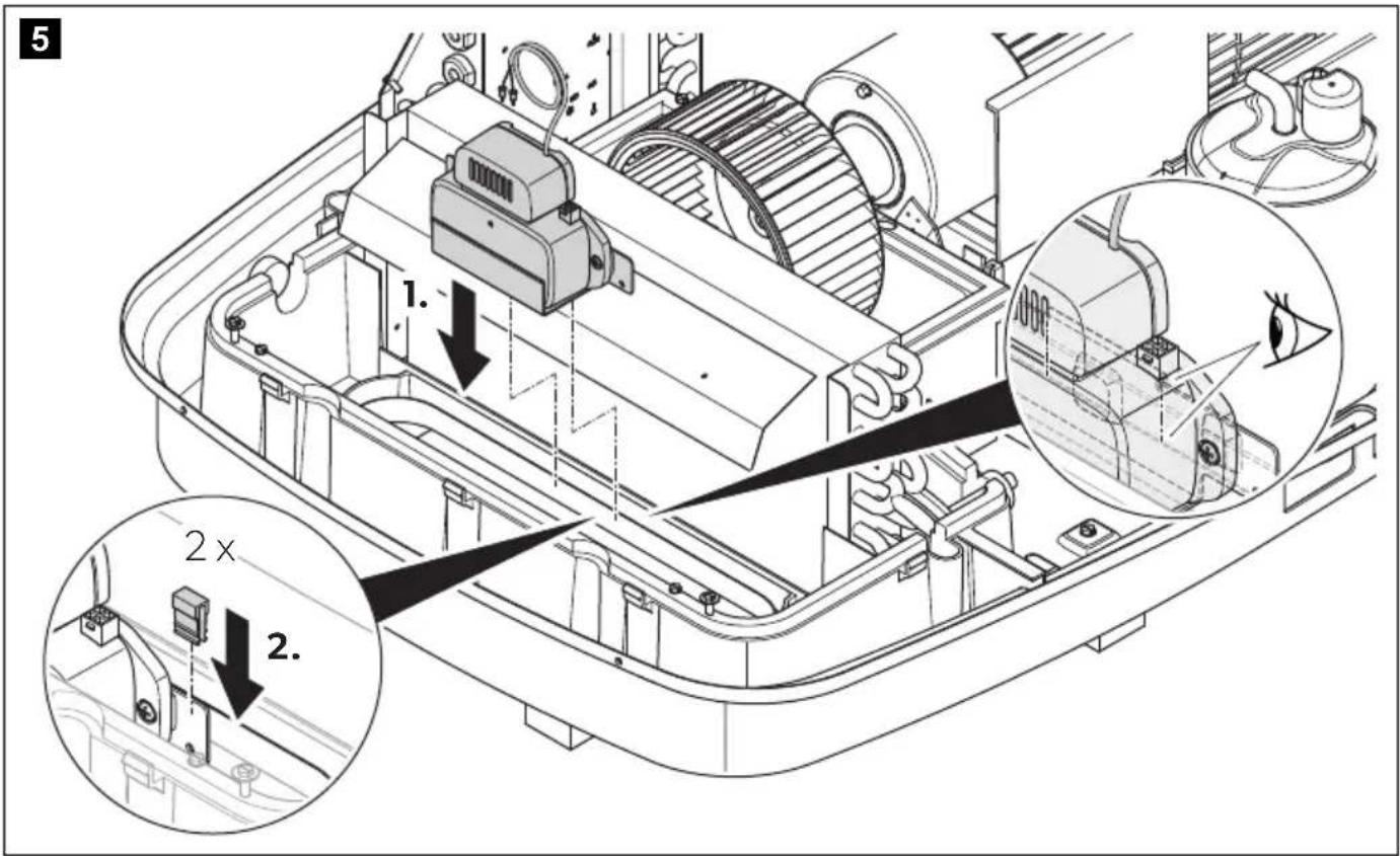
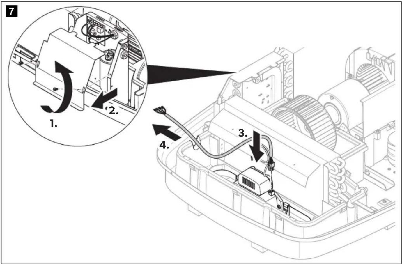
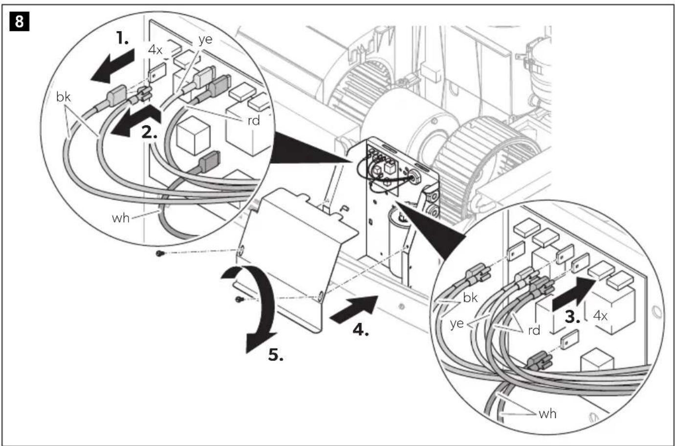
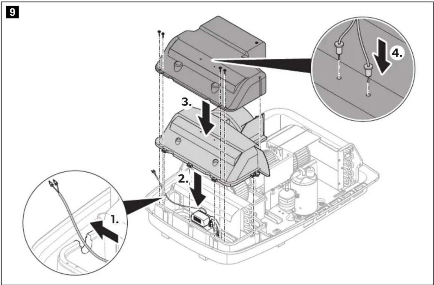
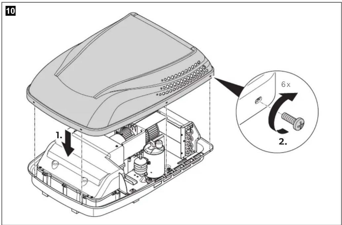
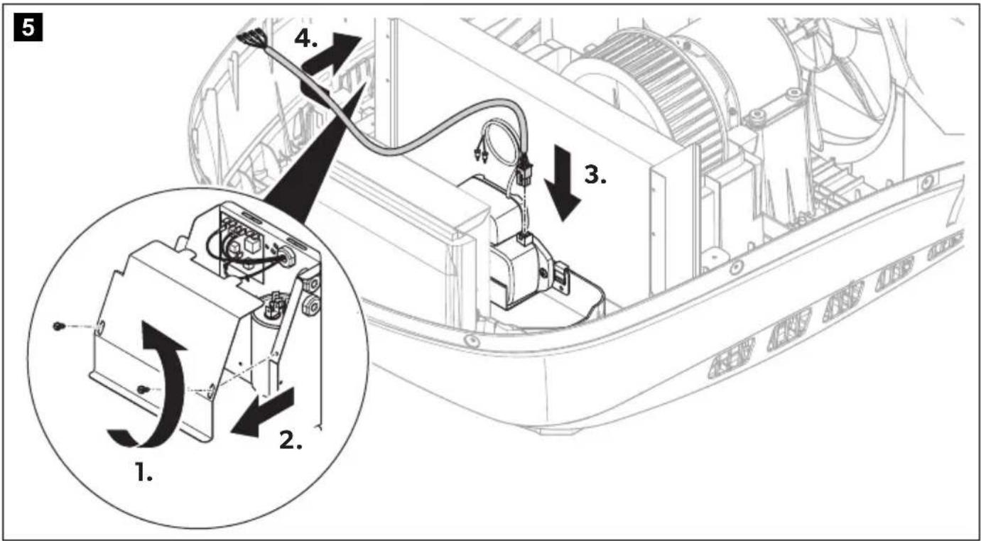
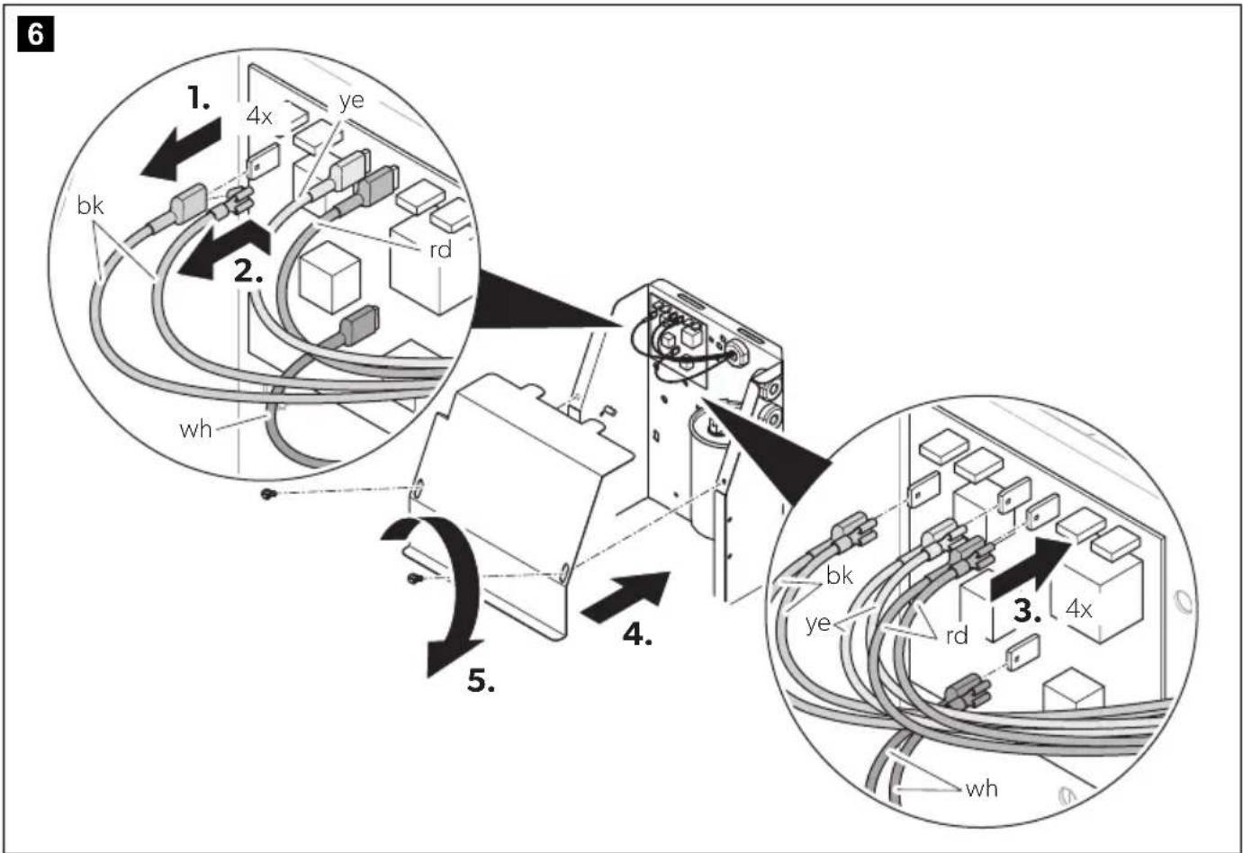
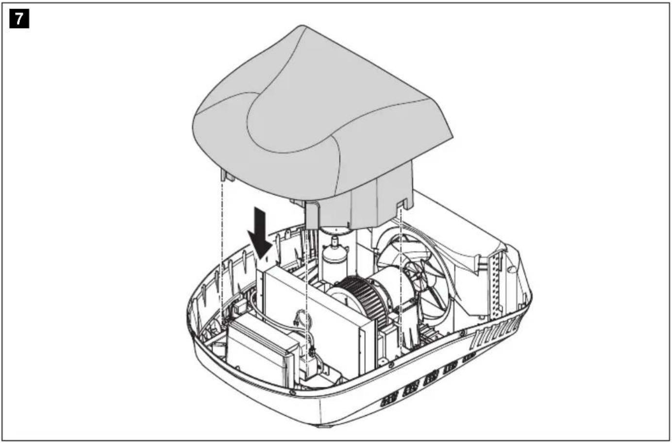
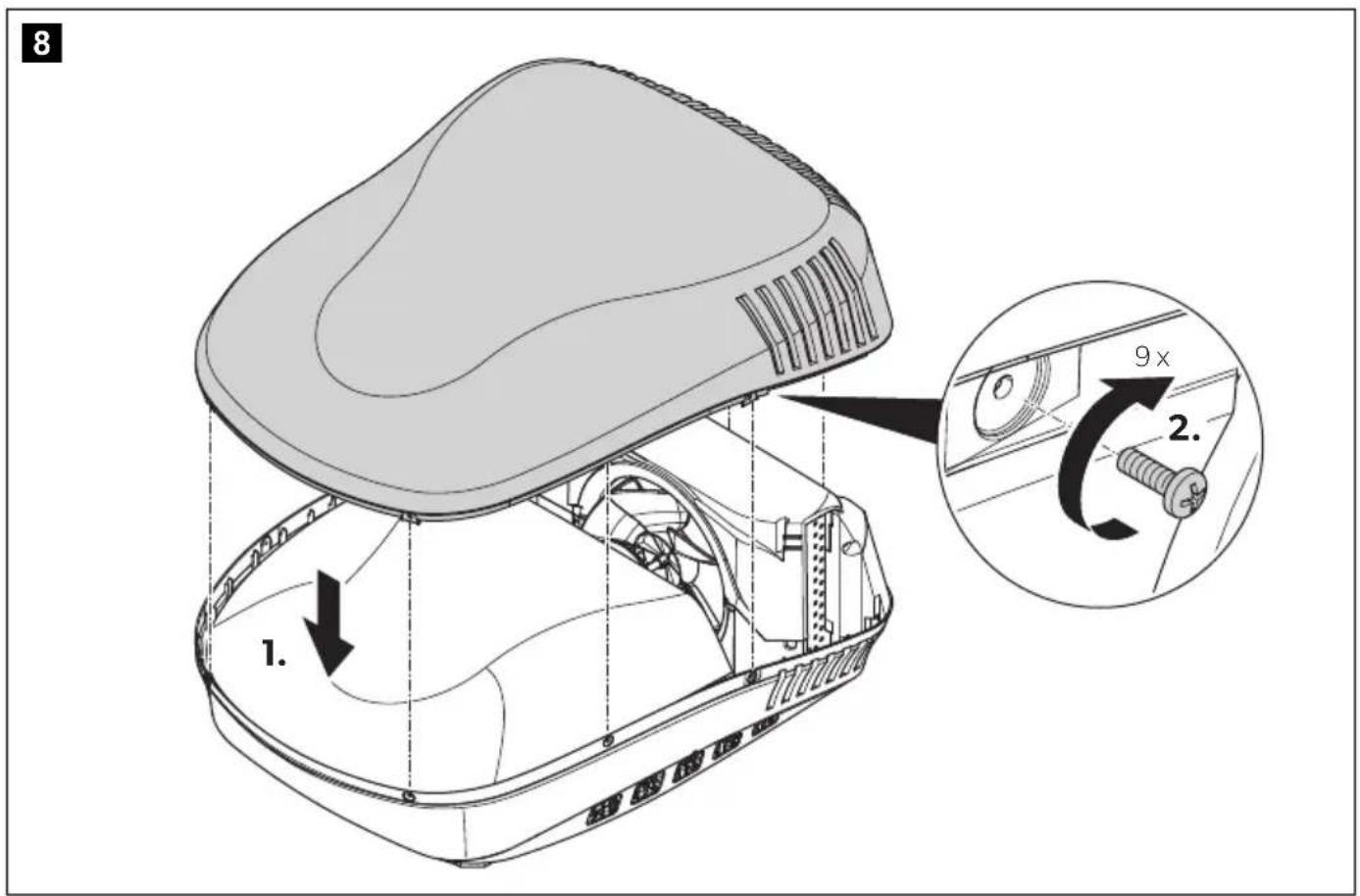
FreshJet Series 3 MECH, FreshJet Series 4 MECH
▶Proceed as shown in chapter "FreshJet Series 3 MECH, FreshJet Series 4 MECH" on page 19.
Penguin II MECH
▶Proceed as shown in chapter "Penguin II MECH" on page 27.
Penguin II ELEC
▶Proceed as shown in chapter "Penguin II ELEC" on page 32.
Blizzard NXT MECH
▶Proceed as shown in chapter "Blizzard NXT MECH" on page 37.
Blizzard NXT ELEC
▶Proceed as shown in chapter "Blizzard NXT ELEC" on page 42.
Brisk II
▶Proceed as shown in chapter "FreshJet (ADB2012)" on page 6.
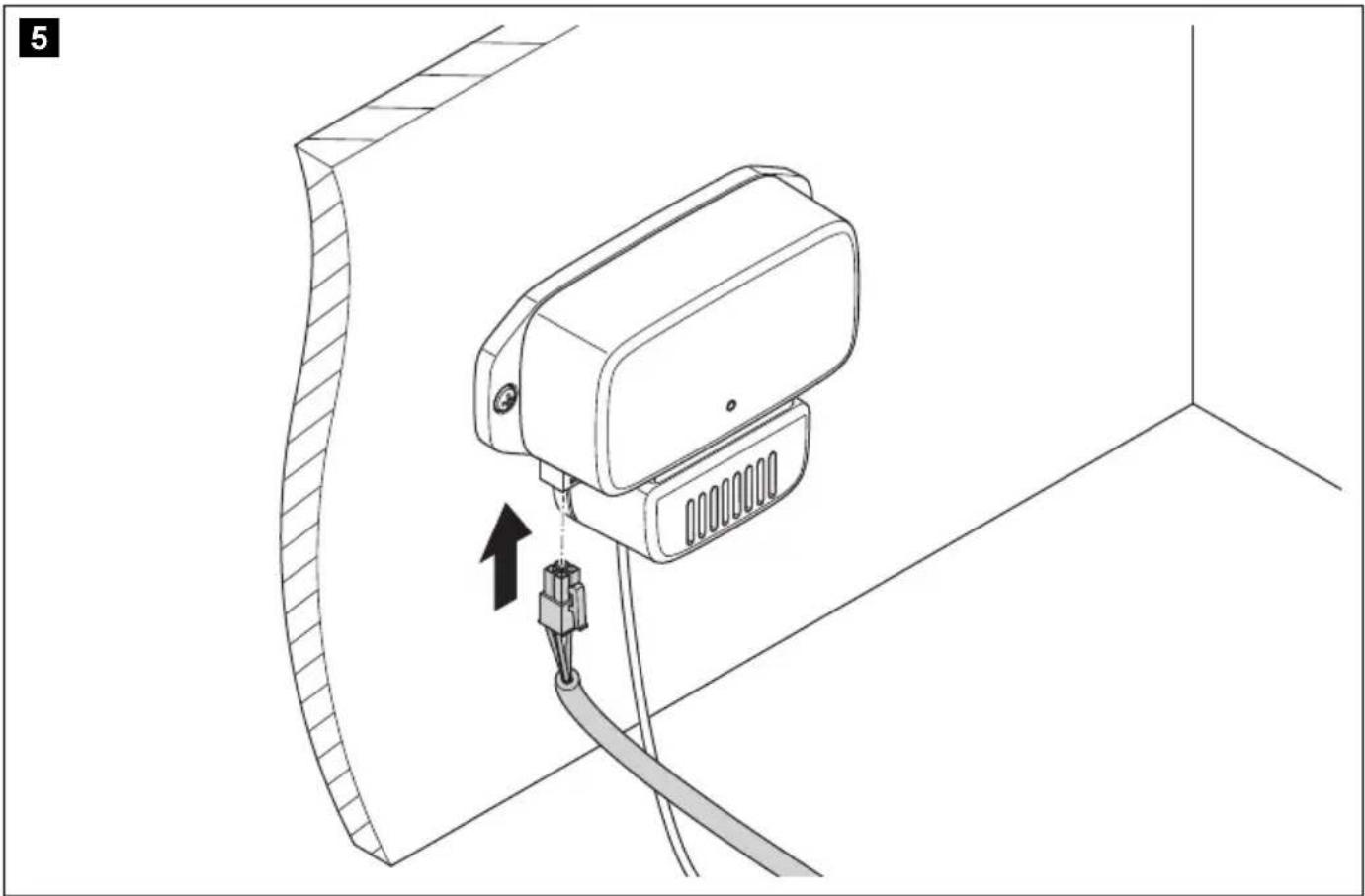
Marine A/C units

NOTICE! Damage hazard
Ensure that you do not to enlarge mounting holes in case you deburr mounting holes with a reamer.
The air purifier can be mounted to a wall in a dry space. Consider the cable lengths to the Marine A/C unit.
▶Proceed as shown in chapter "Marine A/C units" on page 51.
Using the device
The air purifier operates automatically when the air conditioner's fan is activated.
Troubleshooting
If the device does not work as described or the power cable is damaged, contact the manufacturer's service agent (see dometic.com/dealer).
Cleaning and maintenance
▶Check and clean the ionization needle periodically and, if applicable, each time when servicing the air conditioner air filter.
Warranty
Refer to the sections below for information about warranty and warranty support in the US, Canada, and all other regions.
United States and Canada
LIMITED WARRANTY AVAILABLE AT DOMETIC.COM/WARRANTY.
IF YOU HAVE QUESTIONS, OR TO OBTAIN A COPY OF THE LIMITED WARRANTY FREE OF CHARGE, CONTACT:
DOMETIC CORPORATION
MARINE CUSTOMER SUPPORT CENTER
2000 NORTH ANDREWS AVENUE
POMPANO BEACH, FLORIDA, USA 33069
1-800-542-2477
All Other Regions
The statutory warranty period applies. If the product is defective, please contact the manufacturer's branch in your region (dometic.com/dealer) or your retailer.
For repair and warranty processing, please include the following documents when you send in the device:
• A copy of the receipt with purchasing date
- A reason for the claim or description of the fault
FCC
This device complies with Part 15 of the FCC Rules. Operation is subject to the following two conditions:
- This device may not cause harmful interference.
- This device must accept any interference received, including interference that may cause undesired operation.
Changes or modifications not expressly approved by the party responsible for compliance could void the user's authority to operate the equipment.
This equipment has been tested and found to comply with the limits for a Class B digital device, pursuant to part 15 of the FCC Rules. These limits are designed to provide reasonable protection against harmful interference in a residential installation. This equipment generates, uses and can radiate radio frequency energy and, if not installed and used in accordance with the instructions, may cause harmful interference to radio communications. However, there is no guarantee that interference will not occur in a particular installation. If this equipment does cause harmful interference to radio or television reception, which can be determined by turning the equipment off and on, the user is encouraged to try to correct the interference by one or more of the following measures:
- Reorient or relocate the receiving antenna.
- Increase the separation between the equipment and receiver.
- Connect the equipment into an outlet on a circuit different from that to which the receiver is connected.
- Consult the dealer or an experienced radio/TV technician for help.
This device complies with Industry Canada license-exempt RSS standard(s). Operation is subject to the following two conditions:
- This device may not cause interference.
- This device must accept any interference, including interference that may cause undesired operation of the device. This Class B digital apparatus complies with Canadian ICES-3(B)/NMB-3(B).
Disposal
Recycling packaging material

▶
Place the packaging material in the appropriate recycling waste bins wherever possible.
United States
Recycling products with non-replaceable batteries, rechargeable batteries or light sources
Dispose the product in accordance with all applicable regulations.
The product can be disposed free of charge.
All Other Regions
Recycling products with non-replaceable batteries, rechargeable batteries or light sources
If the product contains any non-replaceable batteries, rechargeable batteries or light sources, you don't have to remove them before disposal.
If you wish to finally dispose of the product, ask your local recycling center or specialist dealer for details about how to do this in accordance with the applicable disposal regulations.
The product can be disposed free of charge.
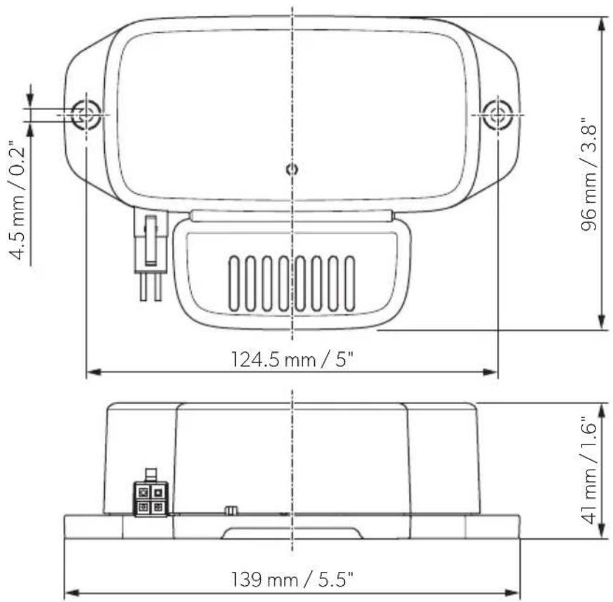
Technical data
| Breathe 2500 Breathe 4500 Breathe 4500 Marine | |||
| SKU 9620000428 9620000 | 427 9620000429 | ||
| Temperature range -10 °C to +45 °C | |||
| Voltage | 100 - 245 V~ /50 - 60 Hz | ||
| Current 20 mA | |||
| Dimensions (L x W x H) | fig. 4, page 5 | ||
| Weight 0.27 kg 0.54 kg 0.36 kg | |||
| Inspection/certification |   10R-06 16457 10R-06 16457 | ||
| Meets California Ozone emissions limit | CARB certified | ||
FreshJet Series 3 MECH, FreshJet Series 4 MECH
Description technique
FreshJet Series 3 MECH, FreshJet Series 4 MECH
FreshJet Series 3 MECH, FreshJet Series 4 MECH
FreshJet Series 3 MECH, FreshJet Series 4 MECH
FreshJet Series 3 MECH, FreshJet Series 4 MECH
FreshJet Series 3 MECH, FreshJet Series 4 MECH
FreshJet Series 3 MECH, FreshJet Series 4 MECH
FreshJet Series 3 MECH, FreshJet Series 4 MECH
▶Gå tillväga enligt kapitel "FreshJet Series 3 MECH, FreshJet Series 4 MECH" på sidan 19.
Penguin II MECH
FreshJet Series 3 MECH, FreshJet Series 4 MECH
FreshJet Series 3 MECH, FreshJet Series 4 MECH
FreshJet Series 3 MECH, FreshJet Series 4 MECH
FreshJet Series 3 MECH, FreshJet Series 4 MECH
FreshJet Series 3 MECH, FreshJet Series 4 MECH
FreshJet Series 3 MECH, FreshJet Series 4 MECH
FreshJet Series 3 MECH, FreshJet Series 4 MECH
dometic.com/sales-offices