
PMF 10 8 Li 1 - Power tool BOSCH - Free user manual and instructions
Find the device manual for free PMF 10 8 Li 1 BOSCH in PDF.
| Brand | Bosch |
| Model | PMF 10 8 Li 1 |
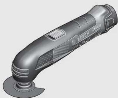
| Tool type | Oscillating multi-tool |
| Rated voltage | 10.8 V |
| No-load speed | 5000 – 20000 rpm |
| Oscillation angle | 1.4° (left/right) |
| Weight (according to EPTA 01:2014) | 0.93 kg |
| Operating temperature | -20 °C to +50 °C |
| Charging temperature | 0 °C to +45 °C |
| Recommended battery | PBA 10.8 V |
| Recommended charger | AL 11..CV |
| Sound pressure level | 81 dB(A) |
| Sound power level | 92 dB(A) |
| Uncertainty (K) | 1.8 dB |
| Main applications | Sawing and cutting of wood, plastics, plaster, non-ferrous metals, soft wall tiles, dry sanding, scraping of small surfaces |
| Integrated safety | Emergency stop via switch, overload protection, automatic shut-off in case of jam, insulated gripping surfaces |
| Maintenance | Clean ventilation slots, replace worn accessories, store in a dry place |
| Included accessories | Plunge saw blade, sanding pad, abrasive sheet, hex key for hex socket screws |
| Repairability | Bosch spare parts only, repair by qualified professional |
| After-sales service | Bosch website or phone contact (0811 360122 in France) |
Frequently Asked Questions - PMF 10 8 Li 1 BOSCH
User questions about PMF 10 8 Li 1 BOSCH
0 question about this device. Answer the ones you know or ask your own.
Ask a new question about this device
Download the instructions for your Power tool in PDF format for free! Find your manual PMF 10 8 Li 1 - BOSCH and take your electronic device back in hand. On this page are published all the documents necessary for the use of your device. PMF 10 8 Li 1 by BOSCH.
USER MANUAL PMF 10 8 Li 1 BOSCH
OBJ BUCH-1170-006 book Page 1 Wednesday, October 12, 2016 11:17 AM
WEU WEU
Robert Bosch Power Tools GmbH
70538 Stuttgart
GERMANY
www.bosch-pt.com
160992A1ZZ(2014.11)AS/118WEU

160992A1ZZ
PMF 10,8 LI
it isnizonal original
nl Ocrsprankelijke
eepuiksaanwijine
OBI_BUCH-1170-006.book Page 8 Wednesday, October 12, 2016 11:17 AM
8|Deutsch
Henk Becker
Executive Vice President Engineering
Helmut Heinzelmann
Head of Product Certification
PT/ECS

iV. k = m _____
Robert Bosch Power Tools GmbH
70538 Stuttgart, GERMANY
Stuttgart, 01.01.2017
Montage
Akku laden
OBI_BUCH-1170-006.book Page 9 Wednesday, October 12, 2016 11:17 AM
OBI_BUCH-1170-006.book Pagc: 10 Wednesday, October 12, 2016 11:17 AM
10|Deutsch
OBI_BUCH-1170-006.book Page 12 Wednesday, October 12, 2016 11:17 AM
12 | Deutsch
Schaben
General Power Tool SafetyWarnings
WARNING
Read all safety warnings and all in
Strucions. Failure to follow the warnings
and instructions may result in electric shock, fire and/or serious injury.
Save all warnings and instructions for future reference.
The term "power tool" in the warnings refers to your mains-operated (cored) power tool or battery-operated (cordless) power tool.
Work area safety
- Keep work area clean and well lit. Cluttered or dark areas invite accidents.
Do not operate power tools in explosive atmospheres, such as in the presence of flammable liquids, gases or dust. Power tools create sparks which may ignite the dust or fumes.
- Keep children and bystanders away while operating a power tool. Distractions can cause you to lose control.
Electrical safety
Power tool plugs must match the outlet. Never modify the plug in any way. Do not use any adapter plugs with earthed (grounded) power tools. Unmodified plugs and matching outlets will reduce risk of electric shock.
- Avoid body contact with earthed or grounded surfaces, such as pipes, radiators, ranges and refrigerators. There is an increased risk of electric shock if your body is earthed or grounded.
Do not expose power tools to rain or wet conditions. Water entering a power tool will increase the risk of electric shock.
Do not abuse the cord. Never use the cord for carrying, pulling or unplugging the power tool. Keep cord away from heat, oil, sharp edges and moving parts. Damaged or entangled cords increase the risk of electric shock.
When operating a power tool outdoors, use an extension cord suitable for outdoor use. Use of a cord suitable for outdoor use reduces the risk of electric shock.
If operating a power tool in a damp location is unavoidable, use a residual current device (RCD) protected supply. Use of an RCD reduces the risk of electric shock.
Personal safety
Stay alert, watch what you are doing and use common sense when operating a power tool. Do not use a power tool while you are tired or under the influence of drugs, alcohol or medication. A moment of inattention while operating power tools may result in serious personal injury.
Use personal protective equipment. Always wear eye protection. Protective equipment such as dust mask, non-skid safety shoes, hard hat, or hearing protection used for appropriate conditions will reduce personal injuries.
Prevent unintentional starting. Ensure the switch is in the off-position before connecting to power source and/or battery pack, picking up or carrying the tool. Carrying power tools with your finger on the switch or energising power tools that have the switch on invites accidents.
Remove any adjusting key or wrench before turning the power tool on. A wrench or a key left attached to a rotating part of the power tool may result in personal injury.
Do not overreach. Keep proper footing and balance at all times. This enables better control of the power tool in unexpected situations.
Dress properly. Do not wear loose clothing or jewellery. Keep your hair, clothing and gloves away from moving parts. Loose clothes, jewellery or long hair can be caught in moving parts.
Bosch Power Tools 1609 92A 1ZZ | (12.10.16)


English | 15
Exercise extreme caution when handling the scraper. The accessory is very sharp; danger of injury.
Product Description and Specifications

Read all safety warnings and all instructions. Failure to follow the warnings and instructions may result in electric shock, fire and/or serious injury.
Intended Use
The machine is intended for sawing and cutting wooden materials, plastic, gypsum, non-ferrous metals and fastening elements (e.g., unhardened nails, staples). It is also suitable for working soft wall tiles, as well as for dry sanding and scraping of small surfaces. It is especially suitable for working close to edges and for flush cutting. Operate the power tool exclusively with Bosch accessories.
Product Features
The numbering of the product features refers to the illustration of the machine on the graphics page.
1 Battery unlocking button
2 Battery pack
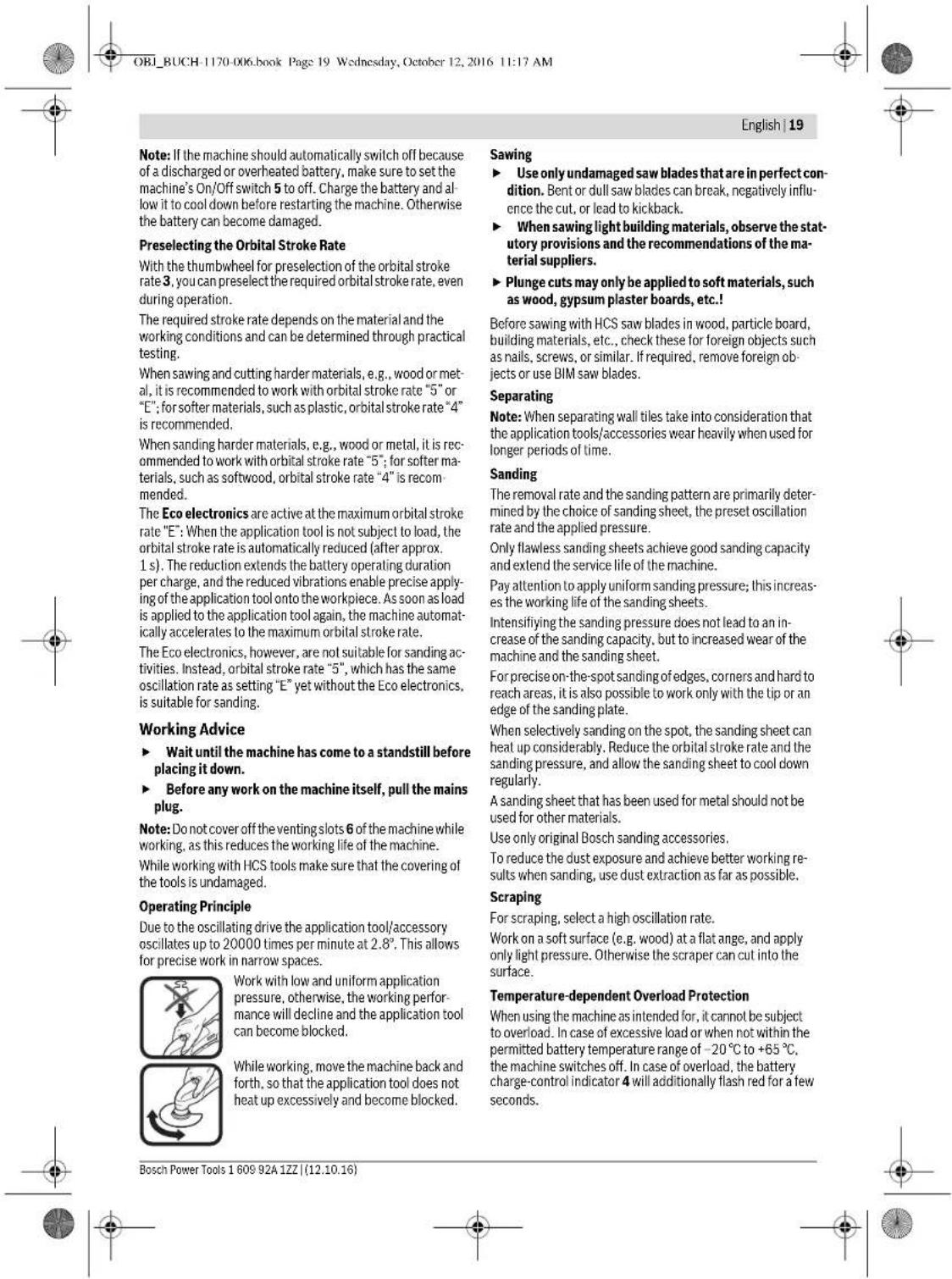
3 Thumbs wheel for orbit frequency preselection
4 Battery charge-control indicator
5 On/Off switch
6 Venting slots
7 Tool holder
8 Handle (insulated gripping surface)
9 Plunge saw blade*
10 Clamping bolt with washer
11 Hex key
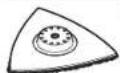
12 Sanding plate*
13 Sanding sheet
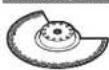
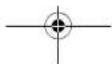
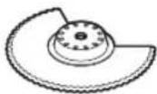
14 Segment saw blade*
15 Felt ring of the dust extraction
16 Retaining clip of the dust extraction
17 Vacuum connection*
18 Dust extraction
19 Vacuum hose
*Accessories shown or described are not part of the standard delivery scope of the product. A complete overview of accessories can be found in our accessories program.
Technical Data
| Multi-function tool PMF 10,8 LI | |
| Article number | 3603 A01 9.. |
| Preselection of orbital stroke rate | ● |
| Rated voltage | V= 10.8 |
| No-load speed n0 | min- 5000-20000 |
| Oscillation angle, left/right | 1.4 |
| Weight according to EPTA-Procedure 01:2014 kg 0.93 | |
| Permitted ambient temperature | |
| -during charging | °C 0...+45 |
| -during o p and during storage | °C -20...+50 |
| Recommended batteries | PBA 10,8V ... |
| Recommended chargers | AL 11...CV |
| *Limited performance at temperatures <0℃ | |
Noise/Vibration Information
Sound emission values determined according to EN 60745-2-4.
Typically the A-weighted noise levels of the product are: Sound pressure level 81 dB(A);Sound power level 92 dB(A). Uncertainty K-1.8 dB.
Wear hearing protection!
Vibration total values a_t (triax vector sum) and uncertainty K determined according to EN 60745:
Sanding: a_h = 4m / s^2 K = 1.5m / s^2 Cutting with plunge cut saw blade: a_h = 20m / s^2 K = 2.0m / s^2 Cutting with segmental saw blade: a_h = 16m / s^2 K = 2.5m / s^2 Scraping: a_h = 6m / s^2 K = 1.5m / s^2
The vibration level given in this information sheet has been measured in accordance with a standardised test given in EN 60745 and may be used to compare one tool with another. It may be used for a preliminary assessment of exposure. The declared vibration emission level represents the main applications of the tool. However if the tool is used for different applications, with different accessories or insertion tools or is poorly maintained, the vibration emission may differ. This may significantly increase the exposure level over the total working period.
An estimation of the level of exposure to vibration should also take into account the times when the tool is switched off or when it is running but not actually doing the job. This may significantly reduce the exposure level over the total working period.
Identify additional safety measures to protect the operator from the effects of vibration such as: maintain the tool and the accessories, keep the hands warm, organisation of work patterns.
Declaration of Conformity
We declare under our sole responsibility that the product described under "Technical Data" is in conformity with all relevant provisions of the directives 2011/65/EU, 2014/30/EU, 2006/42/EC including their amendments and complies with


OBI_BUCH-1170-006.book Page 16 Wednesday, October 12, 2016 11:17 AM
16|English
the following standards: EN 60745-1, EN 60745-2-4, EN 50581.
Technical file (2006/42/EC) at:
Robert Bosch Power Tools GmbH, PT/ECS,
70538 Stuttgart,GERMANY
Henk Becker
Executive Vice President
Engineering
Helmut Heinzelmann
Head of Product Certification PT/ECS

Robert Bosch Power Tools GmbH
70538 Stuttgart,GERMANY
Stuttgart, 01.01.2017
Assembly
Battery Charging
Use only the battery chargers listed on the accessories
page. Only these battery chargers are matched to the lithium-ion battery of your power tool.
Note: The battery supplied is partially charged. To ensure full capacity of the battery, completely charge the battery in the battery charger before using your power tool for the first time.
The lithium-ion battery can be charged at any time without reducing its service life. Interrupting the charging procedure does not damage the battery.
Removing the battery
To remove the battery 2, press the unlocking buttons 1 and pull the battery out of the machine to the rear. Do not exert any force.
Battery Charge-control Indication
When the power tool is switched on, the battery charge-control indicator 4 signals the still available battery capacity or an overload.
Indication Capacity
Continuous lighting, green >70%
Continuous lighting, yellow 30-70%
Continuous lighting, red < 30%
When the battery charge-control indicator 4 flashes red, the machine is subject to overload. Please observe the information in section "Temperature-dependent Overload Protection", page 19.
Changing the Tool
Before any work on the machine itself (e.g. maintenance, tool change, etc.) as well as during transport and storage, remove the battery from the power tool. There is danger of injury when unintentionally actuating the On/Off switch.
Wear protective gloves when changing application tools/accessories. Contact with the application tool/accessory can lead to injuries.
Selecting the Application Tool/Accessory
The following table shows examples for application tools. Further application tools can be found in the extensive Bosch accessories program.
Accessory Material Application
| BIM segment saw blade | Wooden materials, plas-tic, non-ferrous metals | Separating and plunge cuts; also for sawing close to edges, in corners and hard to reach areas; example: shortening already installed bottom rails or door hinges, plunge cuts for adjusting floor panels | |
| Base plate for sand-ing, series Delta 93 mm | Depends on sanding sheet | Sanding surfaces close to edges, in corners or hard to reach areas; depending on the sanding sheet for, e.g., sanding wood, paint, varnish, stone | |
| HCS plunge cut saw blade, wood | Wooden materials, soft plastics | Separating and deep plunge cuts; also for sawing close to edges, in corners and hard to reach areas; example: narrow plunge cut in solid wood for installing a ventilation grid | |
| HCS plunge cut saw blades, wood | Wooden materials, soft plastics | Smaller separating and plunge cuts; example: cut-outs in furniture for cable connections | |
| BIM plunge cut saw blades, metal | Metal (e. g. unhardened nails, screws, smaller pro-files), non ferrous metals | Smaller separating and plunge cuts; example: shortening narrow profiles, cutting fastening elements such as staples |
160992A1ZZ|(12.10.16)BoschPowerTools


OBI_BUCH-1170-006.book Page 17 Wednesday, October 12, 2016 11:17 AM
English | 17
Accessory Material Application
HM Riff segment saw blade
Grouting joints, soft wall tiles, glass-fibre reinforces plastic and other abrasive materials
Cutting and separating close to edges, in corners or hard to reach areas; example: removing grouting joints between wall tiles for repair work, cutting openings in tiles, gypsum boards or plastic
HM-Riff della plate
Mortar, concrete remainders, wood, abrasive materials
Rasping and sanding on hard surfaces; example: removing mortar or tile adhesive (e.g. when replacing damaged tiles)

HM-Riff grout and mortar remover
Mortar, grouting joints, epoxy resin, glass fibre re inforces plastic and other abrasive materials
Removing grouting joints from wall and floor tiles as well as removing mortar and joint adhesive (also in right angled corners)

Scaper, rigid
Carpets, coverings, Scraping on hard surfaces;
example: removing carpet and tile adhesive
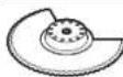
BIM serrated segment saw blade
Insulation material, insulation panels, floor panels, sound insulation panels, cardboard, carpet, rubber, leather
Cutting soft materials
Mounting/Replacing the Application Tool/Accessory
If required, remove an already mounted application tool accessory.
For removing the application tool/accessory loosen the screw 10 with the hex key 11 and remove the tool.
Mount the application tool/accessory (e.g. plunge cut saw blade 9) in such a way on the tool holder 7 that the openings of the tool engage into the caps of the tool holder.
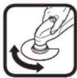
For a safe and fatigue-free working position it is possible to position the application tools/accessories in any snap-in positions on the tool holder. Position the tool in such a way that the depressed centre points downwards (marking on the tool is readable from above, see figure on the graphics page).
Use the screw 10 to fasten the application tool/accessory.
Tightly fasten the screw 10 with the hex key 11.
Check the tight seating of the application tool/accessory. Incorrect or not securely fastened application tools/accessories can come loose during operation and pose a hazard.
Mounting/Replacing a Sanding Sheet on the Sanding Plate
The sanding plate 12 is fitted with Velcro backing for quick and easy fastening of sanding sheets with Velcro adhesion. Before attaching the sanding sheet 13, free the Velcro backing of the sanding plate 12 from any debris by tapping against it in order to enable optimum adhesion.
Position the sanding sheet 13 flush alongside one edge of the sanding plate 12, then lay the sanding sheet onto the sanding plate and press firmly.
To ensure optimum dust extraction, pay attention that the punched holes in the sanding sheet match with the holes in the sanding plate.
To remove the sanding sheet 13, grasp it at one of the tips and pull it off from the sanding plate 12.
You can use all sanding sheets, fleece pads/polishing cloth pads of the Delta 93 mm series of Bosch accessory program. Sanding accessories, such as fleece pads/polishing cloth pads, are attached to the sanding plate in the same manner.


OBI_BUCH-1170-006.book Page 18 Wednesday, October 12, 2016 11:17 AM
18|English
Selecting the Sanding Sheet
Depending on the material to be worked and the required rate of material removal, different sanding sheets are available:
| Sanding disc | Material | Application | Grain size |
| Red quality | - All wooden materials (e. g., hardwood, soft-wood, chipboard, building board) | For coarse sanding, e. g. of rough, unplaned beams and boards | coarse 40 |
| For face sanding and planing small irregularities | medium 80 | ||
| s | 100 | ||
| For finish and fine sanding of wood | fine 180 | ||
| For sanding off paint coarse 40 | 240 | ||
| - Varnish | 320 | ||
| -Filling compo | 400 | ||
| -Filler | For sanding primer (e. g., for removing brush dashes, drops of paint and paint run) | medium 80 | |
| White quality | For final sanding of primers before coating | fine 180 | |
| 240 | |||
| 320 |
Dust/Chip Extraction
Dusts from materials such as lead-containing coatings, some wood types, minerals and metal can be harmful to one's health. Touching or breathing in the dusts can cause allergic reactions and/or lead to respiratory infections of the user or bystanders.
Certain dusts, such as oak or beech dust, are considered as carcinogenic, especially in connection with wood-treatment additives (chromate, wood preservative). Materials containing asbestos may only be worked by specialists.
- As far as possible, use a dust extraction system suitable for the material.
- Provide for good ventilation of the working place.
- It is recommended to wear a P2 filter-class respirator.
Observe the relevant regulations in your country for the materials to be worked.
Prevent dust accumulation at the workplace. Dusts can easily ignite.
Connecting the Dust Extraction (see figure A)
Remove the application tool/accessory when mounting the dust extraction 18 (accessory).
If required, assemble the parts of the dust extraction 18 as shown in the figure. Position the assembled dust extraction onto the machine via the tool holder 7. Turn the dust extraction in such a manner that the cans of the dust extraction engage into the corresponding recesses on the housing. Fasten the dust extraction to the machine with the retaining clip 16 as shown in the figure.
Pay attention that the felt ring 15 is undamaged and faces tightly against the sanding plate 12. Replace a damage felt ring immediately.
Place a vacuum hose 19 (accessory) onto the vacuum connection 17. Connect the vacuum hose 19 with a vacuum cleaner (accessory). An overview for the connection of various vacuum cleaners can be found at the end of these instructions.
The vacuum cleaner must be suitable for the material being worked.
When vacuuming dry dust that is especially detrimental to health or carcinogenic, use a special vacuum cleaner.
Operation
Starting Operation
Inserting the battery
Use only original Bosch lithium-ion batteries with the voltage listed on the nameplate of your power tool.
Using other batteries can lead to injuries and pose a fire hazard.
Note: Use of batteries not suitable for the machine can lead to malfunctions of or cause damage to the power tool.
Insert the charged battery 2 into the handle until it can be felt to engage and faces flush against the handle.
Switching On and Off
To switch on the power tool, push the On/Off switch 5 toward the front in the direction of the "1" on the switch.
To switch off the power tool, push the On/Off switch 5 toward the rear in the direction of the "0" on the switch.
To save energy, only switch the power tool on when using it. The lithium-ion battery is protected against deep discharging by the "Electronic Cell Protection (ECP)". When the battery is empty, the machine is switched off by means of a protective circuit: The inserted tool no longer rotates.


22 | Français
Ponage: a_n = 4m / s^2, K = 1.5m / s^2
Sciage avec lame de scie a plonge: a_n = 20m / s K = 2,0m / s
Sciage avec lame de scie segmentee: a_i = 16m / s^2 K = 2.5m / s^2
Racage: a_1j = 6m / s^2, K = 1.5m / s^2
Henk Becker
Executive Vice President Engineering
Helmut Heinzelmann
Head of Product Certification
PT/ECS

Robert Bosch Power Tools GmbH 70538 Stuttgart, GERMANY
Stuttgart, 01.01.2017
Montage
OBI_BUCH-1170-006.book Page 26 Wednesday, October 12, 2016 11:17 AM
26 | Français
OBI_BUCH-1170-006.book Page 29 Wednesday, October 12, 2016 11:17 AM
Francais 29
Veilazceque loutilelectroportatifinsiquellesouies deventilationsoienttoujourspropresafaind'obtenirun travailimpeccableetur.
Robert Bosch (France) S.A.S.
Henk Becker Helmut Heinzelmann Executive Vice President Head of Product Certification Engineering PT/ECS

iV. k = m _____
Robert Bosch Power Tools GmbH
70538 Stuttgart, GERMANY
Stuttgart, 01.01.2017
OBI_BUCH-1170-006.book Page 35 Wednesday, October 12, 2016 11:17 AM
Espanol 35
OBI_BUCH-1170-006.book Page41 Wednesday, October 12, 2016 11:17 AM

Portugues|41
Dados tecnicos
Henk Becker
Executive Vice President Engineering
Helmut Heinzelmann
Head of Product Certification
PT/ECS

Robert Bosch Power Tools GmbH 70538 Stuttgart, GERMANY Stuttgart, 01.01.2017
Montagem
Colocar o accumulator
Só utiliser acumuladores de ióes de litio Bosch con a tensión indicada no logotipo da sua ferramenta electrónica. A'utilisation de otheros acumuladores pode levar a lesoes e perigo de incendidio.
OBI_BUCH-1170-006.book Page 45 Wednesday, October 12, 2016 11:17 AM
Portugues|45
Serrar
OBI_BUCH-1170-006.book Page:49 Wednesday, October 12, 2016 11:17 AM
Italiano | 49
Executive Vice President Engineering
Head of Product Certification PT/ECS

Robert Bosch Power Tools GmbH
70538 Stuttgart,GERMANY
Stuttgart,01.01.2017
Montaggio
OBI_BUCH-1170-006.book Page 53 Wednesday, October 12, 2016 11:17 AM
Italiano | 53
OBI_BUCH-1170-006.book Page 65 Wednesday, October 12, 2016 11:17 AM
Dansk 65
Slibing: a_n = 4m / s^2, K = 1.5m / s^2
Savning med dyksavklinge: a_h = 20m / s^3 K = 2,0m / s^2
Teknisk dossier (2006/42/EF) yed:
Robert Bosch Power Tools GmbH, PT/ECS,
70538 Stuttgart,GERMANY
Henk Becker
Executive Vice President
Engineering
Helmut Heinzelmann
Head of Product Certification
PT/ECS

Robert Bosch Power Tools GmbH
70538 Stuttgart,GERMANY
Stuttgart, 01.01.2017
Montering
Opladning af akku
Brug kun de ladeaggregater, der findes pa tilbehorsii
den. Kun disse ladeaggregater er afstemi forhold til den
Li-ion-akku, der bruges pa dit el-vaerktaj.
OBI_BUCH-1170-006.book Page 67 Wednesday, October 12, 2016 11:17 AM
Dansk 67
Indsatsvarktoj Materiale Anvendelse
Bi-metal-segment bolge-formet kniv
Isoleringsmaterialie, isoleringplader, bundiplader, trinitydsisoleringsplader, kton, tapepe, gummli, laeder
Gennemskaring af blode materialer
OBI_BUCH-1170-006.book Page: 72 Wednesday, October 12, 2016 11:17 AM
72 | Svenska
Illustreradekomponenter
17 Utsugningsadapter
18 Dammsugutrustning
19 Utsugningsslang
Executive Vice President Engineering
Head of Product Certification PT/ECS

Robert Bosch Power Tools GmbH
70538 Stuttgart,GERMANY
Stuttgart,01.01.2017
Montage
Batteriets laddning
OBI_BUCH-1170-006.book Page 74 Wednesday, October 12, 2016 11:17 AM
74 | Svenska
OBI_BUCH-1170-006.book Page 76 Wednesday, October 12, 2016 11:17 AM
76 | Svenska
Kapning
Bosch Service Center
Telegrafvej 3
2750 Ballerup
Danmark
Tel.: (08) 7501820 (inom Sverige)
Fax: (011) 187691
Transport
De Itliumjbonbatteri som ingar ar underkastade kraven for farligt gods. Anvandaren kan utyterligare forploktilser transportera batteriernaupon vag.
OBI_BUCH-1170-006.book Page 81 Wednesday, October 12, 2016 11:17 AM
Norsk 81
Henk Becker
Executive Vice President Engineering
Helmut Heinzelmann
Head of Product Certification
PT/ECS

Robert Bosch Power Tools GmbH
70538 Stuttgart, GERMANY
Stuttgart, 01.01.2017
160992A1ZZ|(12.10.16)Bosch Power Tools

OBI_BUCH-1170-006.book Page:88 Wednesday,October 12,2016 11:17 AM
88|Suomi
Executive Vice President
Engineering
Helmut Heinzelmann
Head of Product Certification
PT/ECS

Robert Bosch Power Tools GmbH
705.38 Stuttgart,GERMANY
Stuttgart, 01.01.2017
UvapuOlynon
Φoprrn mnatapias
Na xnpaonpoieIe moVoTouc foopntocn ouvapepo- tAOn cAiaB eaptmauw. Moe auoi ofo npopatric ci vai evapoviojevoi mTv muaTpaia ovTowlambda (Li- lonen) nu npovooiaotio nIgcktoq aoc cypiaio.
Ym6eIg: H natapia npabidetaipeikokc pospitiev.ni 1a va eaoaioe Tn Nnnoi tyu nnc nnt aaptacic npenei va tvn opiotcto ofo ptoiin npiv Tnv xnpoiionoiane yia npoiin opa.
HnataiaovntvAolou npoei va opoiael ava nna oyn.
Hdoakomtncphiopioncdev bannetnv npatapla.
Apalopeon maturapiac
Fia vaoapaeote nty mntarapia 2nntane ra nknktpa anouav
deltawcnc1 kai Byalate nty mntarapia ao no naektpko epyaoleo
traovtac nnc ano nty niow nncupia. Mn xpononounoe
pia.
EvdeiKKTADAONCFOPTIONCmmuataplac
H EvE6e1N 4Ya Tn OoPoiTn Tc mApIac oAuroBoeTe Tn dia-00000000000000000000000000000000000000000000000000000000000000
EvEeXwopntiktoTnTa
△apkecpdaiva >70%
△apkekε ktpivo opuc 30-70%
SuvrnpnKaiKaagapiaoc
Apaapeite nV umatapia ano ton kektpko epyaleio npv ano onaohne cpoya oto iolo nKektpko epyale (n.x. ouvtipnoan, aaoyn epyaleoi kTL).kbaoc ka kata nV meapopou kau kai biopaAon/tny
nAnoeuoyue. Se nepimwn aOeItnc evcyonoianq
tou diokom ON/OFF undapei kivovou tropanou.


100|Türkce
Borular, kalorifer petekleri, isticlar ve buzdalaplar gi-bi topraklamis yizeylerle bedensel temasa gelmek- ten kacin. Bedeniniz topraklandigianda buyuk bir elektrik carpma tehileksi ortaya cikar.
Aleti yagmur altunda veya nemli ortamlarda birakmayn. Suyun elektrikli el aleti icine sizmasi elektrik carpma tehlikesini artrir.
Elektrikli el aletini kablosundan tutarak tasmayin, kabloyu kullanar asmayin vya kablodan cekerek fisi ckarmayin. Kabloyu isdan, yagdan, keskin kenarci simlerden vya aletin hareketii parcalarindn uazuk tut. Hasariy vya dolasmis kabloelektrik carpma tehlikesi ini aririr.
Bir elektrikli el aleti ile acik havada calisirken, mutlaka acik havada kullanimaya uygun uzatma kablosu kullainn. Acik havada kullanimaya uygun uzatma kablosunukullinmasi elektrik carpma tehlkinesini aztilr.
Elektriki el aletinin nemli ortamarda calisturlmasi sartsa, mutlaka ariza akimi koruma salteri kullanin. Aiza akimi koruma salterinin kullanimie elektrik carpma tehlikesini azaltir.
Kisilerin Güvenligi
OBI_BUCH-1170-006.book Page 101 Wednesday, October 12, 2016 11:17 AM
Turkce|101
Cok islevli alelter icin guvenlik talimatu
Alet uncun gurunmeyen elektrik kablolarina rastlama olasligi bulunan isleri yaparken elektrikli el aletini izolasylonu tutamagindan tupan. Gerilim lieten kabloriia temas elektrikli el aletinin metal parcalarini da elektrik akima maruz burakabilir ve elektrik carpasmaina neden olabilir.
Bu elektriki el atelini dedase kuru zempara/taqlama isleri icin kullann. Elektriki el atelini icine szabilecek su, elektrik carpma tehlakesinci oneni olc ed artur.
Dikkat! Yangtin tehlikesif! Zimparalanan malzemenin ve zimpara makinesinin asiri olcide sinmamasina dikkat edin. Ise ara vermeden once her defasinda toz haznesini bosaltin. Toz torbasi, mikro filtre, kagit toz torbasindaki (vyte filtre torbasi ve elektrik supurengins filtresindeki) zimpara tozu, elverissiz kosullara, ornegin metaller tajanirken cikan kivilcilar nedeniye kendiliginden tutusabi-lir. Zimpara tozu lak, poliuretan vega diter kimyasal maddeleler kanrsira ve zimparalanan malze meruz unire saqsmadan dolayi sinrasa tehike da ha artar.
- Ellerinizi kesme yaplan yederen uzak tutun. Is parcasini altan kavramayin. Testere bicagli temas yaralanmalara nden olabilir.
Görmüyen sebeke hatlarmi belirlemek icin uygun ta rama cihazlar kullann vya mahalli ikmal sirketen yardin aln. Elektrik kablolarylakontak yangina vya elektrik carpmasina neden olabilir. Bir gaz borusunn hasara ugramasi pattamalara neden olabilir. Su borularma giris maddi zarafa yol acabilir.
Calsirken elektrikl el aletini ili alanilze sikca tutun ve durus poszisyonunuzu gveni olmasina dikkat edin. Elektrikl el aleti ili elle daha gveni kulananilr.
- is parcasini emnlyete aln. Bir germe tertibati veya men-gene il sebitalen is parcasi elle tutmaya oranla daha g-unveni tutulur.
Akuyu acmayin. Kisa devre tehlikesi vardir.

OBI_BUCH-1170-006.book Page 102 Wednesday, October 12, 2016 11:17 AM
102|Turkce
Teknik veriler
| Cok ilevli alet PMF 10,8 LI | ||
| Ürün kodu | 3603 A01 9.. | |
| Titreşimsaysön seçimi | ● | |
| Anna gerlimi | V=10,8 | |
| Bostaki devir saysin0 | dev/dak 5000-20000 | |
| Osilasyon acrisi sol/sag | " | 1,4 |
| Ağırkı EPTA-Procedure01:2014'e gore kg 0,93 | ||
| Izin verilen ortam sicutligi-sa rda | °C | 0...+45 |
| I Şe l'tme:dipelamada | °C | -20...+50 |
| Tavsiye edilen aküller | PBA 10,8 V... | |
| Tavsiye edilen Şarj cihazlari | AL 11..CV | |
| *<0°C sicutlakianda smuli performans | ||
Henk Becker
Executive Vice President
Engineering
Helmut Heinzelmann
Head of Product Certification
PT/ECS

Robert Bosch Power Tools GmbH
70538 Stuttgart, GERMANY
Stuttgart, 01.01.2017
Montaj
Akünun Şarı
Sadee aksesuar sayfasnda belirtilen sarj cihazlari n kullann. Sadee bu sarj cihazlan elektrkli el aletinizde kullanan Li-Jion aküleve uygundur.
OBI_BUCH-1170-006.book Page 103 Wednesday, October 12, 2016 11:17 AM
Turkce 103
Ucun seçilmesi
OBI_BUCH-1170-006.book Page 104 Wednesday, October 12, 2016 11:17 AM
104|Türkce
OBI_BUCH-1170-006.book Page 106 Wednesday, October 12, 2016 11:17 AM
106|Türkce
Bosch San. ve Tic. A.S.
Ahi Evran Cad. No:1 Kat:22
Polaris Plaza
80670 Maslak/Istanbul
BoschUzman Ekibi+90(0212)3671888
Isiklar LTD.STI
Kizilay Cad. No: 16/C Seyhan
Adana
Tel.:03223599710
Tel.: 0322 3591379
Ideal Eletronik Bobinai
Yeni San. Sit. Camiarkasi No:67
Aksaray
Tel.:03822151939
Tel.:03822151246
Bulsan Elektrik
Istanbul Cad. Devrez Sok. Istanbul Carisi
No:48/29 Iskittler
Ankara
Tel.: 0312 3415142
Tel.:03123410203


OBI_BUCH-1170-006.book Page 107 Wednesday, October 12, 2016 11:17 AM
Turkce 107
Faz Makine Bobinai
Sanavi Sit, 663 Sok. No: 18
Antalya
Tel.:02423465876
Tel.: 02423462885
Orsel Bobinai
- San. Sit. 161. Sok. No: 21
Denizli
Tel.:02582620666
Bulut Elektrik
J 2 J 100000000000000000000000000000000000000000000
J
.1g 1 aal y 1 albg 10 L 10
auiu 6 uaiu
gglg gJg jllg auijgSJI oJyai
lalllg jc aullaiaaaiy bailg
aill oJcLdall
Ulaillg UJbll/psIJIg aIjqSsI Jss
!aJjai
:bae gjgglsljglgJ
2012/19/EU 1gjg8d gglw
aigjgJgagjgJg
sall gao pui u y aai
wugjUlaizuwu aJluuul uJySJI
2006/66/EC gJgJd gJU
g aJUU UjUjU/psUjU gaa
Lgio yalaii ayj olajil lc aSliuai
μg sill gjub jc aiiuiaaio aaijbu


:UJUJI/psJIJI
gU U 108 aJU
.
buiS11
.
aabuaagj (20 10 wuJ) aJb aJwJ Uc JauW
aogglgglgagg
aJJIJI aJbIJI aJIJI JJIJI JJIJI JJIJI aJLAAaUwgg
J 1 J 2 J 3 J 4 J 5 J 6 J 7 J 8 J 9 J 10
gJUd y 2gawwJyJUbUjOJgJUgJgJU. .aJyJgSJI oJU JIabJ p+65°C -20°C
aalaae aolb! kssy ydsjll
JgUg 4sj
aui jg 10 aai i g 10 Sui logig 10 aai
glll gpslll ojla aai jlll
.ajjgssj oosll jwoslc! g a2gawol
aullao aaybpaJolalololol
-llg a gblj j0sll
g-20°C jg gjgluJooa baojall jia
.1000000000000000000000000000000000000000000
J. J. J. J. J. J. J. J. J. J. J. J. J. J. J. J. J. J. J. J. J. J. J. J. J. J. J. J. J. J. J. J. J. J. J. J. J. J. J. J. J. J. J. J. J. J. J. J. J. J. J.
.1JUuWUgUdIg UeUqUwSgPjUJI
. Jssll jooalaiill syyu Llaalall gclji
aJg aJal
cIg aJJI
JlsswI aIuJI:la) auiuJ 8aJU J
jbsuui. Lqijg lqai sic laug (..g sall
labg lai aic g
Jgaoo Jc
Jg Jsu Jsu a gull
aui 0 ooi j aibwlgj (g)Riff Jaiu I S c bji
a b u o Jsu
pIaW2I oJgUog juJJ ao
jIb aJz uusuall jlll lss
sic g juiuui xi ci gjoo
JUJIgBgUUBJWJ!
aiuog auii aai jSiliuljLc ijlljdo sa jpo
gwwJl Jc Jj Jj j 100
:gagjllglb jc loglaal lgc oJaaJl
www.bosch-pt.com
aJw oI sIwI oJgW aJgJgW LcIg Joo gS
.1gjg jiaoo 2auiw 0ggsy p5xclw u w g
Jg 1000
Jgall golg aullg
Jd
aJUyduuulguldo uuauiuuiu
aag.1g2,8°Jdawaa 0 20000
aJU 1slou gJUsu JauJawlaa
g aaiog jio jlsj Iaia Jaiow 0c g ooi
.assJUc
1uI UwJg aJyJyJyJU OJy JyJ 8g IJIS JwJUOsc JwJxJLJU
.assj1 jc yasiiw
#
aJwJg aJl
aio aIlaig a
4 1
1jubJI jwJU gIwU b4g uIgJ
Lgagabgaal aaiuall gaaal uas
aaylplwglc HCSjuaial laai lwi
aylplwol .eji .luw log wglg joualss
.ajll jillljuaill Jai p sawlg ojgalsic
4 1j j j j j j j j j j j j j j j j j j j j j j j j j j j j j j j j j j j j j j j j
Jssu uuiy bgyiie y
algb ojol lgol suiw lsc yu wul u g
#
4gagagagagagagagagagagagagagagagagagagagagagagagagagagagagagagagagagagagagagagagagagagagagagagagagagagagagag
Lgduo jll 1sac aagjog oiaol gglu
JmuSJI bao g laa
1 1 1 1 1 1 1 1 1 1 1 1 1 1 1 1 1
auiu<100
aJoo ojiogolj albiu wos li bao Lc akalall el
.6jaiJllg9
JgcljoljI jgljI cbswO sUj y
.0jaiJgJgajulqJl 0sJU JIqWJ!
15 1 g l wj JLoosuwo Jsuw j Looj elso
gjjic ggs JsWgJgJoo bag JgJg
.1JlJIaJaiJI JSLoJg algJg
gagall gll sic s w Jsw oaioll agg Laa
aagjgawgl jLsjzI bawg gajll Jaa .jSjll
aiaio uuiu
aJlalgllasiwjg gw ojoao jg poaiu
.
Jbag aLolg ggygglg pAai
abolw pssiw lgc jksj yosjul
.1Jc g aGg aJIaJI aJI
abg
a 1000 1000 1000 1000 1000 1000 1000 1000 1000 1000 1000 1000 1000 1000 1000 1000 1000 1000 1000 1000 100
/1sawll alio ooyo aaiyul 0dJ 5aJ 5 J 5
gJyI Jn o gU U 1g! aJg g Ja dA
aJI Iab! p. "ECP) aJgjSJI UJIJI Aglg" abwlg
J:psJall EJQ lo sic aJlg g AJLAbwlg aJUg SJI
. Jic Jxll Oxc J
JU JU UJUSSJ OJLJI LJI JIg:abla JU JUSSJ OJLJI GbI pSjoll Jd! bJg gJyaw JU JI gJpSjoll JUJU5.5LbIg JUSSWJAL iJoo abwJg 0gJg,1gJgOa auiu
Laae
3 1 aagaaagaaagaaagaaagaaagaaagaaagaaagaaagaaagaaagaaagaaagaaagaaagaaagaaagaaagaaagaaagaaagaaagaaagaaagaaagaaagaaagaaagaaagaaagaaagaaagaaagaaagaaagaaagaaagaaagaaagaaagaaagaaagaaagaaagaaagaaagaaagaaagaaagaaagaaa
1 5 1 1 1 1 1 1 1 1 1 1 1 1 1 1 1 1 1 1 1 1 1 1 1 1 1 1 1 1 1 1 1 1 1 1 1 1
a aaaa aaaa aaaa aaaa aaaa aaaa aaaa aaaa aaaa aaaa aaaa aaaa aaaa aaaa aaaa aaaa aaaa aaaa aaaa aaaa aaaa aaaa aaaa aaaa aaaa aaaa aaaa aaaa aaaa aaaa aaaa aaaa aaaa aaaa aaaa aaaa aaaa aaaa aaaa aaaa aaaa aaaa aaaa aaaa aaaa aaaa aaaa aaaa aaaa aaaa aaa aa aaaaa aaaaa aaaaa aaaaa aaaaa aaaaa aaaaa aaaaa aaaaa aaaaa aaaaa aaaaa aaaaa aaaaa aaaaa aaaaa aaaaa aaaaa aaaaa aaaaa aaaaa aaaaa aaaaa aaaaa aaaaa aaaaa aaaaa aaaaa aaaaa aaaaa aaaaa aaaaa aaaaa aaaaa aaaaa aaaaa aaaaa aaaaa aaaaa aaaaa aaaaa aaaaa aaaaa aaaaa aaaaa aaaaa aaaaa aaaaa aaaaa aaaaa aaa aa aa aa aa aa aa aa aa aa aa aa aa aa aa aa aa aa aa aa aa aa aa aa aa aa aa aa aa aa aa aa aa aa aa aa aa aa aa aa aa aa aa aa aa aa aa aa aa aa aa aa aa aa aa aa aa aa aa aa aa aa aa aa aa aa aa aa aa aa aa aa aa aa aa aa aa aa aa aa aa aa aa aa aa aa aa aa aa aa aa aa aa aa aa aa aa aa aa aa aa aeaeaeaeaeaeaeaeaeaeaeaeaeaeaeaeaeaeaeaeaeaeaeaeaeaeaeaeaeaeaeaeaeaeaeaeaeaeaeaeaeaeaeaeaeaeaeaeaeaeaeaeaeaeaeaeaeaeaeaeaeaeaeaeaeaeaeaeaeaeaeaeaeaeaeaeaeaeaeaeaeaeaeaeaeaeaeae
jUJU/JLJIb
g jllg g g g g g g g g g g g g g g g g g g g g g g g g g g g g g g g g g g g g g g g g g g g g g g g g g g g g g g g g g g g g g g g g g g g g g g g g
4 Lc 15giv 15s
2900 jiu 1j
jaiy j
jaiy
10gU 10 gU abwUg UabuUg UaUg UauUg UauUg UauUg UauUg UauUg UauUg UauUg UauUg UauUg UauUg UauUg UauUg UauUg UauUg UauUg UauUg UauUg UauUg UauUg UauUg UauUg UauUg UauUg UauUg UauUg UAU
jóánll aojg jiu
:olllgawjagjollaljj jgswsgallgallgall g
| 40 60 | aithia | aithia lal aithia lal al gllg lglg lglg lglg lglg lglg lglg lglg lglg lglg lglg lglg lglg lglg lglg lglg lglg lglg lglg lglg lglg lglg lglg lglg lglg lglg lglg lglg lglg lglg lglg lglg lglg lglg lgl g lglg lglg lglg lglg lglg lglg lglg lglg lglg lglg lglg lglg lglg lglg lglg lglg lglg lglg lglg lglg lglg lglg lglg lglg lglg lglg lglg lglg lglg lglg lglg lglg lglg |
| 80 100 120 | aibwio | aithia lal aithia lal al gllg lglg lglg lglg lglg lglg lglg lglg lglg lglg lglg lglg lglg lglg lglg lglg lglg lglg lglg lglg lglg lglg lglg lglg lglg lglg lglg lglg lglg |
| 180 240 320 400 | aocli | aithia lal aithia lal aithia lal al gllg lglg lglg lglg lglg lglg lglg lglg lglg lglg lglg lglg lglg lglg lglg lglg lglg lglg lglg lglg lglg lglg lglg lglg lglg lglg lglg lglg lglg lglc |
| 40 60 | aithia | aithia lal aithia lal aithia lal al gllg lglg lglg lglg lglg lglg lglg lglg lglg lglg lglg lglg lglg lglg lglg lglg lglg lglg lglg lglg lglg lglg lglg lglg lglg lglg lglg l |
| 80 100 120 | aibwio | aithia lal aithia lal aithia lal al gllg lglg lglg lglg lglg lglg lglg lglg lglg lglg lglg lglg lglg lglg lglg lglg lglg lglg lglg lglg lglg lglg lglg lglg lglg lglg lglg lgt |
| 180 240 320 | aocli | aithia lal aithia lal aithia lal aithia lal al gllg lglg lglg lglg lglg lglg lglg lglg lglg lglg lglg lglg lglg lglg lglg lglg lglg lglg lglg lglg lglg lglg lglg lglg lglg lglg lglg lglg |
j 4 a j 109 a
aJJI Eji
psjll 1 Jlao 2 jg jg jg j
J
Jlduuulal )auiuul o dus J
jua uuu. lajjg lalai sic uug (..g sall
lablg uuswul alao c bauu ll g2g ylo
.0000 uK
Jswu .sall Jlduuwl sic aglg ulga jI
.

aJJI JnWdJU mgo
a aalnnae alnoa uulusl ool ngsl lo sic
j#
70%
jai jiuwa-gw
jaoi jaiu 30-70%
jaojaiuog<30%
JdJdJd
gill gwlgl wgeolj ywll scc no yjoll ljc jsw. wll aal oaii aaiia
2U/0 2,0=K.2U/0 20=ah:μu bI J uJ I J uJ I J
2l/p 2,5=K,²16=a,h:JJI JJIJIJIJIJIJI
2U/fo 1,5=K,²U/fo 6=a h:lau≤U
Llaalllg jgSdalllgljimssgnoa
EN60745 1
Senior Vice President
Engineering
Helmut Heinzelmann
Head of Product Certification
PT/ECS


Robert Bosch Power Tools GmbH,
70538 Stuttgart,GERMANY
Stuttgart, 01.01.2017
U
pSjJ j
aao 1c o9sdoJnJooJg pao
jlll luee ngsdoa aaii ojaai j!.gill
Lg o saiuol guiuul Uligo Jo lo
auijoo
j jw aal y gogg jaiu w:abalo
Jolss Jsw jw wll oj yos Jn nn
aLoSJI pSjJIolJ oJgUlaJ UgUlaWbI
g g g uu
jul dlaac g6g jy 2. aio o jig no sall jgs
.
jgaaJl|j
aJySJI oJgWJ JI OJgZJJI jj Siiu
.aaababwI gWJd aao yogagall
1
*p2j1 2
Lauu gajll ssc bao dac 3
pJJIJJ Jw dJU wgo 4
labyIg uusuill elao 5
aagai gao 6
7
(ugjoo yolal sbw) ggu yao 8
* 9
aLgo wUg1 10
11
- gaiy dya 12
*oaiJllgj9 13
J 1 J 1 J 1 J 1 J 1 J 1 J 1 J 1 J 1 J 1 J 1 J 1 J 1 J 1 J 1 J 1 J 1 J 1 J 1 J 1 J 1 J 1 J 1 J 1 J 1 J 1 J 1 J 1 J 1 J 1 J 1 J 1 J 1 J 1 J
J. J. J. J. J. J. J. J. J. J. J. J. J. J. J. J. J. J. J. J. J. J. J. J. J. J. J. J. J. J. J. J. J. J. J. J. J. J. J. J. J. J. J. J. J. J. J. J. J. J. J.
g (100 111111 g) aaii11 sglalbss
auiuui ooi i111111 uji j auij
Jgawabwugaaagagjllal
aolll jkssd. alall slgallge
bukul uuul sgo nnu wu no
oacn . buokall palsw sic dyw kujial
29g yauu ukuu dagla uuu
Ig aai Iog
aJdJIU UeAolIg
gbsic 105j 1. cullg
sds cullg a dall lalol
gljw jy yjgll oall g /g

Jaaai Jlae
Jg 100 g 100 g 100 g 100 g 100 g 100 g 100 g 100 g 100 g 100 g 100 g 100 g 100 g 100 g 100 g 100 g 100 g 100 g 100 g 100 g 100
gbaa hagd aagadai jaoepdaillc gla 1a liu jilus pj gll oal gbal aga lcball Jksw kgsj ksgj kss
bglw lLl j. clll 0d m 1g
Jl Jlwl . 0aui Jall Jalg Jlwl
Jl g d q aann all Jowj A yj kJ
. obl Jkll Og
山
p5jogjollolwgloloo
jllnssl o jg bao pslalnns lglal y gwi jpa aaii jp no qol sswy pnlqal no nnoe gil aasall nwl o jg .palsl no jEgi 0qol s
ai
L L 111111111111111111
aasol
aolsswglg jll g 100 100 100 100 100 100 100 100 100 100 100 100 100 100 100 100 100 100 100 100 100 100 100 100 100 10
<jcalosuw
aaiolla 1 aalb aabaii aaiolaa iin bglg jnlll llll 0g n. a9 s0
yjwaiall psslll jilw yds d3 aal o
. g|jia| |g| ouiu
4.lasaiw2g
aJdJ 4 JJIJIJIJIJIJIJIJIJIJIJIJIJIJIJIJIJIJIJIJIJIJIJIJIJIJIJIJIJIJIJIJIJIJIJIJIJIJIJIJIJIJIJIJIJIJIJIJIJIJIJIJIJIJIJIJIJIJIJIJIJIJIJIJIJIJIJIJIJIJIJIJIJIJIJIJIJIJIJIJIJIJIJIJIJIJIJIJIJIJIJIJIJIJIJIJIJIJIJIJIJ
山
oJaiI JooI Uos
jill jll lcljla jic alg jall 1. aaioll auiu jsl bglal jwll o se Ijai u jy s q yu bs ayu do auiu 1. auiu sdo u 1s gij auiu jsl o sdu ayu 1. baq glauiu uuiu jsl o daiu 1. bao u uuiu uuiu o daiu u uui
aaiagbw
Jg Jlgl Lg g Jg Jg Jg Jg Jg Jg Jg Jg Jg Jg Jg Jg Jg Jg Jg Jg Jg Jg Jg Jg Jg Jg Jg Jg Jg Jg Jg Jg Jg Jg Jg Jg Jg Jg Jg Jg Jg Jg Jg Jg Jg Jg Jg Jg Jg Jg Jg Jg Jg Jg J
a lo =la2b
JuiiJI Jai aowlo U. Jaaal abg Coo 29j yao jolao uS w
loJ
Jolai
auijE 8. jaiy auijgS JdJI
JU U gS lo sic gI uio u gS lo sic
alol oui puc . agsgl gJgssll gl Udoall
UgDg daiu jgSLOOeL piaiwi sic odag
.
jgl jagggl gios. jalal agll slic jil j 2ggl gglg jzj1n jaglgl jolgl jda j0, ju, ujgSJ ooll Juswlg egi n jd 2g jy
Jl lal y Ia g 10 a b a y jy JI 10
. g 1g 1g 1g 1g
o 10 10 10 10
a 10 10 10 10
a 10 10 10 10
a 10 10 10 10
g gaiall gl oal yg d aJySLI 2g jaiol jjgl jgl jgs
g 1000000000000000000000000000000000000000000000000000000000000000000000000000000000000000000
aJyjS Jd SdWg aLoa Jn
LJwJ 1JGJJ 1000000000000000000000000000000000000000000000000000000000000000000000000000000000000
g 1 g 1 g 1 g 1 g 1 g 1 g 1 g 1 g 1 g 1 g 1 g 1 g 1 g 1 g 1 g 1 g 1 g 1 g 1 g 1 g 1 g 1 g 1 g 1 g 1 g 1 g 1 g 1 g 1 g 1 g 1 g 1 g 1 g 1 g
Lgolssy 8 yll ayljySsI Llalb0y 2. Jlalb0y I1n jc I yd s
eJypl gI gI yd yJyIyIyIySL
Lgolssw pJ n! oJyIyIyIySL
. 6JnGJyIyIyIyIy
Lc uo .uJyIyIySL
pUu JyIyIyIyIy
JUu JyIyIyIy
JUu JyIyIy
JUu JyIy
JUu JyIy
JUu JyIy
abwgljLJyIg dai JI ailg baa Jc
Jal
aui jgSll sall aolc au doo UdoLo
A 1
1g5 no 5u. gJUu uuiu Jnuiuuiuuiuuiuuiuuiuuiuuiuuiuuiuuiuuiuuiuuiuuiuuiuuiuuiuuiuuiuuiuuiuuiuuiuuiuuiuuiuuiuuiuuiuuiuuiuuiuuiuuiuuiuuiuuiuuiuuiuuiuuiuuiuuiuuiuuiuuiuuiuuiuuiuui uuuuuuuuuuuuuuuuuuuuuuuuuuuuuuuuuuuuuuuuuuuuuuuuuuuuuuuuuuuuuuuuuuuuuuuuuuuuuuuuuuuuuuuuuuuuuuuuuuuuuuuuuuuuuuuuuuuuuuuuuuuuuuuuuuuuuuuuuuuuuuuuuuuuuuuuuuu uu
JshuI Jka Jlo
A
4 bag jolj q. aasps sssglag jn g ljlg gglg g jg jg jg jg jg jg jg jg jg jg jg jg jg jg jg jg jg jg jg jg jg jg jg jg jg jg jg jg jg jg jg jg jg jg jg jg jg jg jg jg jg jg jg jg jg jg jg jg jg jg j
aai 8 . aui jssll ooi Josu wloic s
yJyJU JU
JgA Jn Jl gI y Jy Jy AaJ 100000000000000000000000000000000000000000000000000000000000000000000000000
1jbjjfofo
<JcJpaJ
4aJLJI≤J1
A uL a
gaiuJSEi
JuswUda
4aJLgSJJ o


- WEU WEU
- PMF 10,8 LI
- 8|Deutsch
- Montage
- Akku laden
- 10|Deutsch
- | Deutsch
- Schaben
- General Power Tool SafetyWarnings
- WARNING
- Work area safety
- Electrical safety
- Personal safety
- Product Description and Specifications
- Intended Use
- Product Features
- Noise/Vibration Information
- Wear hearing protection!
- Declaration of Conformity
- 16|English
- Assembly
- Battery Charging
- Removing the battery
- Battery Charge-control Indication
- Indication Capacity
- Changing the Tool
- Selecting the Application Tool/Accessory
- Accessory Material Application
- Mounting/Replacing the Application Tool/Accessory
- Mounting/Replacing a Sanding Sheet on the Sanding Plate
- 18|English
- Selecting the Sanding Sheet
- Dust/Chip Extraction
- Connecting the Dust Extraction (see figure A)
- Operation
- Starting Operation
- Inserting the battery
- Switching On and Off
- | Français
- | Français
- Veilazceque loutilelectroportatifinsiquellesouies deventilationsoienttoujourspropresafaind'obtenirun travailimpeccableetur.
- Montagem
- Colocar o accumulator
- Serrar
- Italiano | 49
- Montaggio
- Italiano | 53
- Dansk 65
- Montering
- Opladning af akku
- Indsatsvarktoj Materiale Anvendelse
- | Svenska
- Illustreradekomponenter
- Batteriets laddning
- | Svenska
- | Svenska
- Kapning
- Transport
- Norsk 81
- 88|Suomi
- UvapuOlynon
- Φoprrn mnatapias
- Apalopeon maturapiac
- EvdeiKKTADAONCFOPTIONCmmuataplac
- EvEeXwopntiktoTnTa
- SuvrnpnKaiKaagapiaoc
- 100|Türkce
- Kisilerin Güvenligi
- Cok islevli alelter icin guvenlik talimatu
- Montaj
- Akünun Şarı
- Ucun seçilmesi
- 104|Türkce
- 106|Türkce
- auiu 6 uaiu
- buiS11
- aullao aaybpaJolalololol
- aJg aJal
- cIg aJJI
- Jg Jsu Jsu a gull
- pIaW2I oJgUog juJJ ao
- www.bosch-pt.com
- Jd
- #
- abg
- Laae
- jUJU/JLJIb
- jóánll aojg jiu
- J
- j#
- U
- pSjJ j
- jgaaJl|j
- Ig aai Iog
- Jaaai Jlae
- oJaiI JooI Uos
Brand : BOSCH
Model : PMF 10 8 Li 1
Category : Power tool