
PMF 1900 E SET - Power tool BOSCH - Free user manual and instructions
Find the device manual for free PMF 1900 E SET BOSCH in PDF.
| Product type | Oscillating multi-function power tool |
| Brand | Bosch |
| Model | PMF 1900 E SET |
| Article number | 3 603 A00 5.. |
| Rated power input | 190 W |
| Useful power output | 89 W |
| No-load speed | 15000 – 21000 rpm |
| Oscillation angle | 1.4° (left/right) |
| Weight | 1.2 kg (according to EPTA-Procedure 01:2014) |
| Protection class | /II (double insulation) |
| Rated voltage | 230 V |
| Sound pressure level | 86 dB(A) |
| Sound power level | 97 dB(A) |
| Vibration (sanding) | a_h = 3.5 m/s², K = 1.5 m/s² |
| Vibration (plunge-cut sawing) | a_h = 12.5 m/s², K = 1.5 m/s² |
| Vibration (segmented sawing) | a_h = 14 m/s², K = 2.5 m/s² |
| Vibration (scraping) | a_h = 12 m/s², K = 1.5 m/s² |
| Power supply | Mains (power cord) |
| Applications | Sawing, cutting, sanding, scraping, rasping; plunge cuts and near-edge work |
| Included accessories | Plunge-cut saw blade, sanding plate, abrasive sheet, depth stop, hex key, clamping screw |
| Maintenance and cleaning | Clean ventilation slots regularly; use a wire brush for Riff tools; disconnect before any maintenance |
| Safety | Wear protective equipment (goggles, mask, gloves); disconnect before adjustment or accessory change; do not use in explosive atmospheres |
| Spare parts and repairability | Available at www.bosch-pt.com; repair by qualified professional only |
| After-sales service France | 0811 360122 (local cost); contact.outillage-electroportatif@fr.bosch.com |
| Certifications | CE, compliance with directives 2011/65/EC, 2014/30/EC, 2006/42/EC |
Frequently Asked Questions - PMF 1900 E SET BOSCH
User questions about PMF 1900 E SET BOSCH
0 question about this device. Answer the ones you know or ask your own.
Ask a new question about this device
Download the instructions for your Power tool in PDF format for free! Find your manual PMF 1900 E SET - BOSCH and take your electronic device back in hand. On this page are published all the documents necessary for the use of your device. PMF 1900 E SET by BOSCH.
USER MANUAL PMF 1900 E SET BOSCH
OBJ_BUCH-345-012.book Page 1 Tuesday, November 10, 2015 5:24 PM
WEU WEU
natural_image
Illustration of a Bosch electric shaver tool (no text or symbols visible)Robert Bosch Power Tools GmbH
70538 Stuttgart
GERMANY
www.bosch-pt.com
1609 92A 214 (2014.11) T/91

PMF
190 E | 1900 E

BOSCH
English ...... Page 11
Français....Page 18
4
A
natural_image
Line drawing of a power tool with meshing and adjustment knobs (no text or symbols)
∅ 19 mm:
2 600 793 009 (3 m)
1 610 793 002 (5 m)

2 607 000 748
PAS 12-27 F
PAS 12-27
PAS 11-21
Deutsch | 5
Deutsch
Sicherheitshinweise
Executive Vice President
Engineering
Helmut Heinzelmann
Head of Product Certification
PT/ETM9


Robert Bosch Power Tools GmbH
70538 Stuttgart, GERMANY
Stuttgart, 01.01.2017
Montage
Werkzeugwechsel
General Power Tool Safety Warnings
WARNING
Read all safety warnings and all instructions. Failure to follow the warnings
and instructions may result in electric shock, fire and/or serious injury.
Save all warnings and instructions for future reference.
The term “power tool” in the warnings refers to your mains-operated (corded) power tool or battery-operated (cordless) power tool.
Work area safety
- Keep work area clean and well lit. Cluttered or dark areas invite accidents.
▶ Do not operate power tools in explosive atmospheres, such as in the presence of flammable liquids, gases or dust. Power tools create sparks which may ignite the dust or fumes.
▶ Keep children and bystanders away while operating a power tool. Distractions can cause you to lose control.
Electrical safety
▶ Power tool plugs must match the outlet. Never modify the plug in any way. Do not use any adapter plugs with earthed (grounded) power tools. Unmodified plugs and matching outlets will reduce risk of electric shock.
▶ Avoid body contact with earthed or grounded surfaces, such as pipes, radiators, ranges and refrigerators. There is an increased risk of electric shock if your body is earthed or grounded.
▶ Do not expose power tools to rain or wet conditions. Water entering a power tool will increase the risk of electric shock.


12 | English
▶ Do not abuse the cord. Never use the cord for carrying, pulling or unplugging the power tool. Keep cord away from heat, oil, sharp edges and moving parts. Damaged or entangled cords increase the risk of electric shock.
▶ When operating a power tool outdoors, use an extension cord suitable for outdoor use. Use of a cord suitable for outdoor use reduces the risk of electric shock.
▶ If operating a power tool in a damp location is unavoidable, use a residual current device (RCD) protected supply. Use of an RCD reduces the risk of electric shock.
Personal safety
▶ Stay alert, watch what you are doing and use common sense when operating a power tool. Do not use a power tool while you are tired or under the influence of drugs, alcohol or medication. A moment of inattention while operating power tools may result in serious personal injury.
▶ Use personal protective equipment. Always wear eye protection. Protective equipment such as dust mask, non-skid safety shoes, hard hat, or hearing protection used for appropriate conditions will reduce personal injuries.
▶ Prevent unintentional starting. Ensure the switch is in the off-position before connecting to power source and/or battery pack, picking up or carrying the tool. Carrying power tools with your finger on the switch or energising power tools that have the switch on invites accidents.
Remove any adjusting key or wrench before turning the power tool on. A wrench or a key left attached to a rotating part of the power tool may result in personal injury.
▶ Do not overreach. Keep proper footing and balance at all times. This enables better control of the power tool in unexpected situations.
▶ Dress properly. Do not wear loose clothing or jewellery. Keep your hair, clothing and gloves away from moving parts. Loose clothes, jewellery or long hair can be caught in moving parts.
▶ If devices are provided for the connection of dust extraction and collection facilities, ensure these are connected and properly used. Use of dust collection can reduce dust-related hazards.
Power tool use and care
▶ Do not force the power tool. Use the correct power tool for your application. The correct power tool will do the job better and safer at the rate for which it was designed.
▶ Do not use the power tool if the switch does not turn it on and off. Any power tool that cannot be controlled with the switch is dangerous and must be repaired.
▶ Disconnect the plug from the power source and/or the battery pack from the power tool before making any adjustments, changing accessories, or storing power tools. Such preventive safety measures reduce the risk of starting the power tool accidentally.
▶ Store idle power tools out of the reach of children and do not allow persons unfamiliar with the power tool or these instructions to operate the power tool. Power tools are dangerous in the hands of untrained users.
- Maintain power tools. Check for misalignment or binding of moving parts, breakage of parts and any other
condition that may affect the power tool's operation. If damaged, have the power tool repaired before use. Many accidents are caused by poorly maintained power tools.
- Keep cutting tools sharp and clean. Properly maintained cutting tools with sharp cutting edges are less likely to bind and are easier to control.
▶ Use the power tool, accessories and tool bits etc. in accordance with these instructions, taking into account the working conditions and the work to be performed. Use of the power tool for operations different from those intended could result in a hazardous situation.
Service
▶ Have your peer tool serviced by a qualified repair person using only identical replacement parts. This will ensure that the safety of the power tool is maintained.
Safety Warnings for Multi-function Tools
Hold power tool by insulated gripping surfaces, when performing an operation where the cutting accessory may contact hidden wiring or its own cord. Cutting accessory contacting a "live" wire may make exposed metal parts of the power tool "live" and could give the operator an electric shock.
▶ Use the machine only for dry sanding. Penetration of water into the machine increases the risk of an electric shock.
▶ Caution, fire hazard! Avoid overheating the object being sanded as well as the sander. Always empty the dust collector before taking breaks. In unfavourable conditions, e.g., when sparks emit from sanding metals, sanding debris in the dust bag, micro filter or paper sack (or in the filter sack or filter of the vacuum cleaner) can self-ignite. Particularly when mixed with remainders of varnish, polyurethane or other chemical materials and when the sanding debris is hot after long periods of working.
- Keep hands away from the sawing range. Do not reach under the workpiece. Contact with the saw blade can lead to injuries.
▶ Use suitable detectors to determine if utility lines are hidden in the work area or call the local utility company for assistance. Contact with electric lines can lead to fire and electric shock. Damaging a gas line can lead to explosion. Penetrating a water line causes property damage or may cause an electric shock.
When working with the machine, always hold it firmly with both hands and provide for a secure stance. The power tool is guided more secure with both hands.
- Secure the workpiece. A workpiece clamped with clamping devices or in a vice is held more secure than by hand.
▶ Wear protective gloves when changing application tools/accessories. Application tools/accessories become hot after prolonged usage.
▶ Do not scrape wetted materials (e.g. wallpaper) or on moist surfaces. Penetration of water into the machine increases the risk of an electric shock.
▶ Do not treat the surface to be worked with solvent-containing fluids. Materials being warmed up by the scraping can cause toxic vapours to develop.


English | 13
▶ Use extreme caution when handling blades and scrapers. The application tools are very sharp. Danger of injury.
▶ Products sold in GB only: Your product is fitted with a BS 1363/A approved electric plug with internal fuse (ASTA approved to BS 1362). If the plug is not suitable for your socket outlets, it should be cut off and an appropriate plug fitted in its place by an authorised customer service agent. The replacement plug should have the same fuse rating as the original plug. The severed plug must be disposed of to avoid a possible shock hazard and should never be inserted into a mains socket elsewhere.
Products sold in AUS and NZ only: Use a residual current device (RCD) with a rated residual current of 30 mA or less.
Product Description and Specifications

Read all safety warnings and all instructions. Failure to follow the warnings and instructions may result in electric shock, fire and/or serious injury.
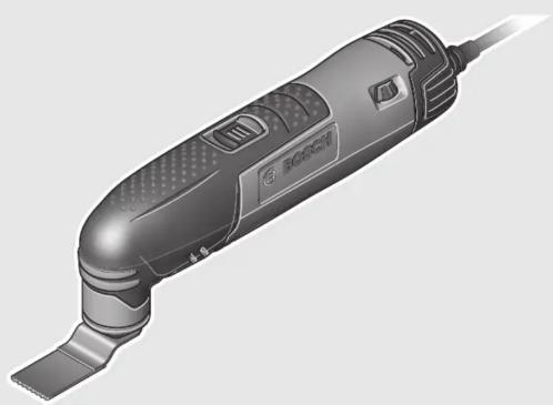
Intended Use
The machine is intended for sawing and cutting wooden materials, plastic, gypsum, non-ferrous metals and fastening elements (e.g., unhardened nails, staples). It is also suitable for working soft wall tiles, as well as for dry sanding and scraping of small surfaces. It is especially suitable for working close to edges and for flush cutting. Operate the power tool exclusively with Bosch accessories.
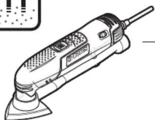
Product Features
The numbering of the product features refers to the illustration of the machine on the graphics page.
1 On/Off switch
3 Venting slots
5 Tool holder
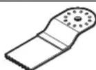
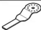
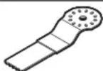
6 Plunge saw blade
7 Clamping bolt with washer
8 Hex key
9 Sanding plate
2 Thumbwheel for orbit frequency preselection
4 Handle (insulated gripping surface)
10 Sanding sheet
11 Depth stop
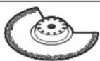
12 Segment saw blade
13 Vacuum hose*
14 Vacuum connection*
15 Fastening screw of the dust extraction*
16 Dust extraction*
17 Felt ring of the dust extraction*
*Accessories shown or described are not part of the standard delivery scope of the product. A complete overview of accessories can be found in our accessories program.
Technical Data
| Multi-function tool PMF 190 E | PMF 1900 E | |
| Article number | 3 603 A00 5.. | |
| Preselection of orbital stroke rate | ● | |
| Rated power input | W | 190 |
| Output power | W | 89 |
| No-load speed n_0 | min^-1 | 15000–21000 |
| Oscillation angle, left/right | ° | 1.4 |
| Weight according to EPTA-Procedure 01:2014 | kg 1.2 | |
| Protection class | /II | |
| The values given are valid for a nominal voltage [U] of 230 V. For different voltages and models for specific countries, these values can vary. | ||
Noise/Vibration Information
Sound emission values determined according to EN 60745-2-4.
Typically the A-weighted noise levels of the product are: Sound pressure level 86 dB(A); Sound power level 97 dB(A). Uncertainty K = 3 dB.
Wear hearing protection!
Vibration total values a_h (triax vector sum) and uncertainty K determined according to EN 60745: Sanding: a_h = 3.5 m/s^2 , K = 1.5 m/s^2 Cutting with plunge cut saw blade: a_h = 12.5 m/s^2 , K = 1.5 m/s Cutting with segmental saw blade: a_h = 14 m/s^2 , K = 2.5 m/s^2 Scraping: a_h = 12 m/s^2 , K = 1.5 m/s^2 .
The vibration level given in this information sheet has been measured in accordance with a standardised test given in EN 60745 and may be used to compare one tool with another. It may be used for a preliminary assessment of exposure. The declared vibration emission level represents the main applications of the tool. However if the tool is used for different applications, with different accessories or insertion tools or is poorly maintained, the vibration emission may differ. This may significantly increase the exposure level over the total working period. An estimation of the level of exposure to vibration should also take into account the times when the tool is switched off or when it is running but not actually doing the job. This may significantly reduce the exposure level over the total working period.
Identify additional safety measures to protect the operator from the effects of vibration such as: maintain the tool and the accessories, keep the hands warm, organisation of work patterns.
Declaration of Conformity
CE
We declare under our sole responsibility that the product described under “Technical Data” is in conformity with all relevant provisions of the directives 2011/65/EU, 2014/30/EU, 2006/42/EC including their amendments and complies with the following standards: EN 60745-1, EN 60745-2-4, EN 50581.


14 | English
Technical file (2006/42/EC) at:
Robert Bosch Power Tools GmbH, PT/ETM9,
70538 Stuttgart, GERMANY
Henk Becker
Executive Vice President
Engineering
Helmut Heinzelmann
Head of Product Certification
PT/ETM9

Assembly
Changing the Tool
▶ Before any work on the machine itself, pull the mains plug.
▶ Wear protective gloves when changing application tools/accessories. Contact with the application tool/accessory can lead to injuries.
Robert Bosch Power Tools GmbH
70538 Stuttgart, GERMANY
Stuttgart, 01.01.2017
Selecting the Application Tool/Accessory
The following table shows examples for application tools. Further application tools can be found in the extensive Bosch accessories program.
Accessory Material Application
1609 92A 214 | (10.11.15) Bosch Power Tools
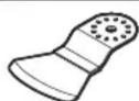
Separating and plunge cuts; also for sawing close to edges, in corners and hard to reach areas; example: shortening already installed bottom rails or door hinges, plunge cuts for adjusting floor panels
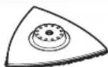
Sanding surfaces close to edges, in corners or hard to reach areas; depending on the sanding sheet for, e.g., sanding wood, paint, varnish, stone
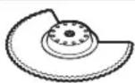
Separating and deep plunge cuts; also for sawing close to edges, in corners and hard to reach areas; example: narrow plunge cut in solid wood for installing a ventilation grid
Smaller separating and plunge cuts; example: cut-outs in furniture for cable connections
Smaller separating and plunge cuts; example: shortening narrow profiles, cutting fastening elements such as staples
Cutting and separating close to edges, in corners or hard to reach areas; example: removing grouting joints between wall tiles for repair work, cutting openings in tiles, gypsum boards or plastic
Rasping and sanding on hard surfaces; example: removing mortar or tile adhesive (e.g. when replacing damaged tiles)
ing on hard surfaces; example: removing carpet and tile adhesive
Cutting soft materials


English | 15
Mounting/Replacing the Application Tool/Accessory
If required, remove an already mounted application tool/accessory.
For removing the application tool/accessory loosen the screw 7 with the hex key 8 and remove the tool.
Mount the application tool/accessory (e.g. plunge cut saw blade 6) in such a way on the tool holder 5 that the openings of the tool engage into the cams of the tool holder.
For a safe and fatigue-free working position it is possible to position the application tools/accessories in any snap-in positions on the tool holder. Position the tool in such a way that the depressed centre points downwards (marking on the tool is readable from above, see figure on the graphics page).
Use the screw 7 to fasten the application tool/accessory. Tightly fasten the screw 7 with the hex key 8.
▶ Check the tight seating of the application tool/accessory. Incorrect or not securely fastened application tools/accessories can come loose during operation and pose a hazard.
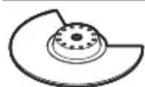
Mounting and Adjusting the Depth Stop
The depth stop 11 can be used when working with segment saw blades, Riff-segment saw blades and segment blades.
If required, remove an already mounted application tool/accessory.
Slide the depth stop 11 over and beyond the tool holder 5 to the stop onto the gear head of the power tool with the labelled side facing upward.
The depth stop is intended for the following cutting depths:
- With segment saw blades ACZ 85 .. with a diameter of 85 mm: 8 mm, 10 mm, 12 mm and 14 mm cutting depths (see indication on the depth stop in large font and not in brackets).
- With segment saw blades ACZ 100 .. with a diameter of 100 mm: 14 mm, 16 mm, 18 mm and 20 mm cutting depths (see indication on the depth stop in smaller font and brackets).
Insert the appropriate segment saw blade for the desired cutting depth. Slide the depth stop 11 from the tool holder 5 in the direction of the application tool until you can rotate it freely. Rotate the depth stop 11 so that the desired cutting depth is above the section of the saw blade, which will be used to saw. Slide the depth stop 11 once again to the stop onto the gear head of the application tool.
For all other cutting depths and when working with other application tools, remove the depth stop 11. For this, remove the application tool and pull the depth stop from the gear head.
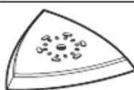
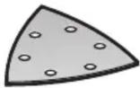
Mounting/Replacing a Sanding Sheet on the Sanding Plate
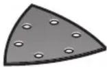
The sanding plate 9 is fitted with Velcro backing for quick and easy fastening of sanding sheets with Velcro adhesion.
Before attaching the sanding sheet 10, free the Velcro backing of the sanding plate 9 from any debris by tapping against it in order to enable optimum adhesion.
Position the sanding sheet 10 flush alongside one edge of the sanding plate 9, then lay the sanding sheet onto the sanding plate and press firmly.
To ensure optimum dust extraction, pay attention that the punched holes in the sanding sheet match with the holes in the sanding plate.
To remove the sanding sheet 10, grasp it at one of the tips and pull it off from the sanding plate 9.
You can use all sanding sheets, fleece pads/polishing cloth pads of the Delta 93 mm series of Bosch accessory program.
Sanding accessories, such as fleece pads/polishing cloth pads, are attached to the sanding plate in the same manner.
Selecting the Sanding Sheet
Depending on the material to be worked and the required rate of material removal, different sanding sheets are available:
Sanding disc Material Application Grain size
 Red quality Red quality | - All wooden materials (e.g., hardwood, soft-wood, chipboard, build-ing board)- Metal materials | For coarse-sanding, e.g. of rough, unplaned beams and boards | coarse 40 | 60 |
| For face sanding and planing small irregularities | medium 80 | 100120 | ||
| For finish and fine sanding of wood | fine 180 | 240320400 | ||
 White quality White quality | - Paint- V a r n i s h-Filling compound-Filler | For sanding off paint coarse 40 | 60 | |
| For sanding primer (e.g., for removing brush dashes, drops of paint and paint run) | medium 80 | 100120 | ||
| For final sanding of primers before coating | fine 180 | 240320 |
Bosch Power Tools 1 609 92A 214 | (10.11.15)


16 | English
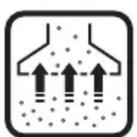
Dust/Chip Extraction
Dusts from materials such as lead-containing coatings, some wood types, minerals and metal can be harmful to one's health. Touching or breathing-in the dusts can cause allergic reactions and/or lead to respiratory infections of the user or bystanders.
Certain dusts, such as oak or beech dust, are considered as carcinogenic, especially in connection with wood-treatment additives (chromate, wood preservative). Materials containing asbestos may only be worked by specialists.
- As far as possible, use a dust extraction system suitable for the material.
- Provide for good ventilation of the working place.
- It is recommended to wear a P2 filter-class respirator.
Observe the relevant regulations in your country for the materials to be worked.
▶ Prevent dust accumulation at the workplace. Dusts can easily ignite.
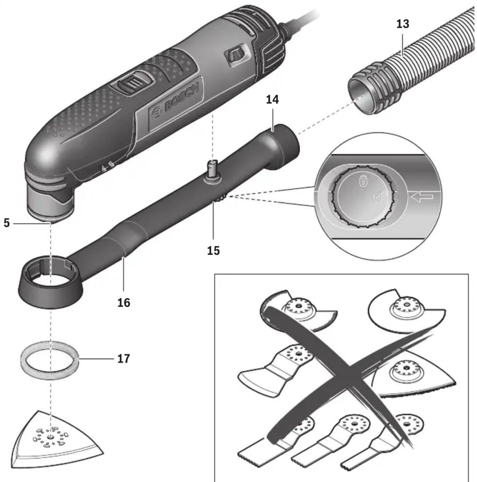
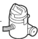
Connecting the Dust Extraction (see figure A)
The dust extraction 16 is intended only when working with the sanding plate 9; it is not of use in combination with other application tools.
For sanding, always connect the dust extraction.
To mount the dust extraction 16 (accessory), remove the application tool and the depth stop 11.
Slide the dust extraction 16 over and beyond the tool holder 5 to the stop onto the gear head of the power tool. Insert fastening screw 15 into the corresponding recess on the housing. To lock the screw, turn it to the position.
Pay attention that the felt ring 17 is undamaged and faces tightly against the sanding plate 9. Replace a damage felt ring immediately.
Place a vacuum hose 13 (accessory) onto the vacuum connection 14. Connect the vacuum hose 13 with a vacuum cleaner (accessory).
An overview for connecting to various vacuum cleaners can be found on the graphics page.
The vacuum cleaner must be suitable for the material being worked.
When vacuuming dry dust that is especially detrimental to health or carcinogenic, use a special vacuum cleaner.
To remove the dust extraction 16, turn fastening screw 15 to the position and pull the dust extraction from the gear head of the power tool.
Operation
Starting Operation
▶ Observe the mains voltage! The voltage of the power source must correspond with the data on the type plate of the machine.
Switching On and Off
To start the machine, push the On/Off switch 1 forward so that the “I” is indicated on the switch.
To switch off the machine, push the On/Off switch 1 toward the rear so that the “0” is indicated on the switch.
To save energy, only switch the power tool on when using it.
Preselecting the Orbital Stroke Rate
With the thumbwheel for preselection of the orbital stroke rate 2, you can preselect the required orbital stroke rate, even during operation.
The required stroke rate depends on the material and the working conditions and can be determined through practical testing.
When sawing, cutting and sanding harder materials, e.g., wood or metal, it is recommended to work with orbital stroke rate “6”; for softer materials, such as plastic, orbital stroke rate “4” is recommended.
Working Advice
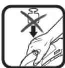
▶ Wait until the machine has come to a standstill before placing it down.
▶ Before any work on the machine itself, pull the mains plug.
Note: Do not cover off the venting slots 3 of the machine while working, as this reduces the working life of the machine.
While working with HCS tools make sure that the covering of the tools is undamaged.
Operating Principle
Due to the oscillating drive the application tool/accessory oscillates up to 21000 times per minute at 2.8^ . This allows for precise work in narrow spaces.
Work with low and uniform application pressure, otherwise, the working performance will decline and the application tool can become blocked.
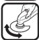
While working, move the machine back and forth, so that the application tool does not heat up excessively and become blocked.
Sawing
▶ Use only undamaged saw blades that are in perfect condition. Bent or dull saw blades can break, negatively influence the cut, or lead to kickback.
- When sawing light building materials, observe the statutory provisions and the recommendations of the material suppliers.
- Plunge cuts may only be applied to soft materials, such as wood, gypsum plaster boards, etc.!
Before sawing with HCS saw blades in wood, particle board, building materials, etc., check these for foreign objects such as nails, screws, or similar. If required, remove foreign objects or use BIM saw blades.


English | 17
Separating
Note: When separating wall tiles take into consideration that the application tools/accessories wear heavily when used for longer periods of time.
Sanding
The removal rate and the sanding pattern are primarily determined by the choice of sanding sheet, the preset oscillation rate and the applied pressure.
Only flawless sanding sheets achieve good sanding capacity and extend the service life of the machine.
Pay attention to apply uniform sanding pressure; this increases the working life of the sanding sheets.
Intensifying the sanding pressure does not lead to an increase of the sanding capacity, but to increased wear of the machine and the sanding sheet.
For precise on-the-spot sanding of edges, corners and hard to reach areas, it is also possible to work only with the tip or an edge of the sanding plate.
When selectively sanding on the spot, the sanding sheet can heat up considerably. Reduce the orbital stroke rate and the sanding pressure, and allow the sanding sheet to cool down regularly.
A sanding sheet that has been used for metal should not be used for other materials.
Use only original Bosch sanding accessories.
For sanding, always connect the dust extraction.
Scraping
For scraping, select a high oscillation rate.
Work on a soft surface (e.g. wood) at a flat ange, and apply only light pressure. Otherwise the scraper can cut into the surface.
Maintenance and Service
Maintenance and Cleaning
▶ Before any work on the machine itself, pull the mains plug.
▶ For safe and proper working, always keep the machine and ventilation slots clean.
Clean Riff application tools (accessory) regularly with a wire brush.
If the replacement of the supply cord is necessary, this has to be done by Bosch or an authorized Bosch service agent in order to avoid a safety hazard.
After-sales Service and Application Service
Our after-sales service responds to your questions concerning maintenance and repair of your product as well as spare parts. Exploded views and information on spare parts can also be found under:
www.bosch-pt.com
Bosch's application service team will gladly answer questions concerning our products and their accessories.
In all correspondence and spare parts order, please always include the 10-digit article number given on the type plate of the machine.
Great Britain
Robert Bosch Ltd. (B.S.C.)
P.O. Box 98
Broadwater Park
North Orbital Road
Denham
Uxbridge
UB 9 5HJ
At www.bosch-pt.co.uk you can order spare parts or arrange the collection of a product in need of servicing or repair.
Tel. Service: (0844) 7360109
E-Mail: boschservicecentre@bosch.com
Ireland
Origo Ltd.
Unit 23 Magna Drive
Magna Business Park
City West
Dublin 24
Tel. Service: (01) 4666700
Fax: (01) 4666888
Australia, New Zealand and Pacific Islands
Robert Bosch Australia Pty. Ltd.
Power Tools
Locked Bag 66
Clayton South VIC 3169
Customer Contact Center
Inside Australia:
Phone: (01300) 307044
Fax: (01300) 307045
Inside New Zealand:
Phone: (0800) 543353
Fax: (0800) 428570
Outside AU and NZ:
Phone: +61 3 95415555
www.bosch.com.au
Republic of South Africa
Customer service
Hotline: (011) 6519600
Gauteng - BSC Service Centre
35 Roper Street, New Centre
Johannesburg
Tel.: (011) 4939375
Fax: (011) 4930126
E-Mail: bsctools@icon.co.za
KZN - BSC Service Centre
Unit E, Almar Centre
143 Crompton Street
Pinetown
Tel.: (031) 7012120
Fax: (031) 7012446
E-Mail: bsc.dur@za.bosch.com
Western Cape – BSC Service Centre
Democracy Way, Prosperity Park
Milnerton
Tel.: (021) 5512577
Fax: (021) 5513223
E-Mail: bsc@zsd.co.za


18 | Français
Bosch Headquarters
Midrand, Gauteng
Tel.: (011) 6519600
Fax: (011) 6519880
E-Mail: rbsa-hq.pts@za.bosch.com
Disposal
The machine, accessories and packaging should be sorted for environmental-friendly recycling.
Do not dispose of power tools into household waste!
Only for EC countries:
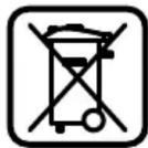
According to the European Guideline 2012/19/EU for Waste Electrical and Electronic Equipment and its implementation into national right, power tools that are no longer usable must be collected separately and disposed of in an environmentally correct manner.
Subject to change without notice.
Français
Executive Vice President
Engineering
Helmut Heinzelmann
Head of Product Certification
PT/ETM9

i.v. k=mc
Robert Bosch Power Tools GmbH
70538 Stuttgart, GERMANY
Stuttgart, 01.01.2017
Montage
Changement d'outil
Robert Bosch (France) S.A.S.
Executive Vice President
Engineering
Helmut Heinzelmann
Head of Product Certification
PT/ETM9


Robert Bosch Power Tools GmbH
70538 Stuttgart, GERMANY
Stuttgart, 01.01.2017
Montaje
Cambio de útil
Executive Vice President
Engineering
Helmut Heinzelmann
Head of Product Certification
PT/ETM9


Robert Bosch Power Tools GmbH
70538 Stuttgart, GERMANY
Stuttgart, 01.01.2017
Montagem
Troca de ferramenta
Executive Vice President Engineering
Head of Product Certification PT/ETM9

Robert Bosch Power Tools GmbH
70538 Stuttgart, GERMANY Stuttgart, 01.01.2017
Montaggio
Executive Vice President Engineering
Helmut Heinzelmann
Head of Product Certification PT/ETM9


Robert Bosch Power Tools GmbH 70538 Stuttgart, GERMANY Stuttgart, 01.01.2017
Montage
Executive Vice President
Engineering
Helmut Heinzelmann
Head of Product Certification
PT/ETM9
jus 3e0 i.v. h:m
Robert Bosch Power Tools GmbH
70538 Stuttgart, GERMANY
Stuttgart, 01.01.2017
Montering
Værktøjsskift
Bosch Service Center
Telegrafvej 3
2750 Ballerup
På www.bosch-pt.dk kan der online bestilles reservedele eller oprettes en reparations ordre.
Tlf. Service Center: 44898855
Fax: 44898755
E-Mail: vaerktoej@dk.bosch.com
Bortskaffelse
Executive Vice President
Engineering
Helmut Heinzelmann
Head of Product Certification
PT/ETM9

i.v. k=m
Robert Bosch Power Tools GmbH
70538 Stuttgart, GERMANY
Stuttgart, 01.01.2017
Montage
Verktygsbyte
Bosch Service Center
Telegrafvej 3
2750 Ballerup
Danmark
Tel.: (08) 7501820 (inom Sverige)
Fax: (011) 187691
Avfallshantering
Executive Vice President Engineering
Helmut Heinzelmann
Head of Product Certification PT/ETM9

Robert Bosch Power Tools GmbH
70538 Stuttgart, GERMANY
Stuttgart, 01.01.2017
Montering
Verktøyskifte
Executive Vice President Engineering
Helmut Heinzelmann
Head of Product Certification PT/ETM9


Robert Bosch Power Tools GmbH
70538 Stuttgart, GERMANY
Stuttgart, 01.01.2017
Asennus
Työkalunvaihto
Executive Vice President
Engineering
Helmut Heinzelmann
Head of Product Certification
PT/ETM9

i.v. k=m
Robert Bosch Power Tools GmbH
70538 Stuttgart, GERMANY
Stuttgart, 01.01.2017
Συναρμολόγηση
Executive Vice President
Engineering
Helmut Heinzelmann
Head of Product Certification
PT/ETM9


Robert Bosch Power Tools GmbH
70538 Stuttgart, GERMANY
Stuttgart, 01.01.2017
Montaj
Uç değiştirme
Bosch San. ve Tic. A.S.
Ahi Evran Cad. No:1 Kat:22
Polaris Plaza
80670 Maslak/Istanbul
Bosch Uzman Ekibi +90 (0212) 367 18 88
Işıklar LTD.ŞTI.
Kızılay Cad. No: 16/C Seyhan
Adana
Tel.: 0322 3599710
Tel.: 0322 3591379
natural_image
Technical line drawing of a mechanical pipe fitting with flanged ends and a central hub (no text or symbols)2 609 256 C55


- WEU WEU
- PMF
- BOSCH
- Deutsch | 5
- Deutsch
- Sicherheitshinweise
- Montage
- Werkzeugwechsel
- General Power Tool Safety Warnings
- WARNING
- Save all warnings and instructions for future reference.
- Work area safety
- Electrical safety
- | English
- Personal safety
- Power tool use and care
- Service
- Safety Warnings for Multi-function Tools
- Product Description and Specifications
- Intended Use
- Product Features
- Noise/Vibration Information
- Wear hearing protection!
- Declaration of Conformity
- CE
- | English
- Assembly
- Changing the Tool
- Selecting the Application Tool/Accessory
- English | 15
- Mounting/Replacing the Application Tool/Accessory
- Mounting and Adjusting the Depth Stop
- Mounting/Replacing a Sanding Sheet on the Sanding Plate
- Selecting the Sanding Sheet
- | English
- Dust/Chip Extraction
- Connecting the Dust Extraction (see figure A)
- Operation
- Starting Operation
- Switching On and Off
- Preselecting the Orbital Stroke Rate
- Working Advice
- Operating Principle
- Sawing
- English | 17
- Separating
- Sanding
- Scraping
- Maintenance and Service
- Maintenance and Cleaning
- After-sales Service and Application Service
- www.bosch-pt.com
- Great Britain
- Ireland
- Australia, New Zealand and Pacific Islands
- Republic of South Africa
- Customer service
- Gauteng - BSC Service Centre
- KZN - BSC Service Centre
- Western Cape – BSC Service Centre
- | Français
- Bosch Headquarters
- Disposal
- Only for EC countries:
- Français
- Changement d'outil
- Montaje
- Cambio de útil
- Montagem
- Troca de ferramenta
- Montaggio
- Montering
- Værktøjsskift
- Bortskaffelse
- Verktygsbyte
- Avfallshantering
- Verktøyskifte
- Asennus
- Työkalunvaihto
- Συναρμολόγηση
- Montaj
- Uç değiştirme
Brand : BOSCH
Model : PMF 1900 E SET
Category : Power tool