
STEB 65 Quick - Saw METABO - Free user manual and instructions
Find the device manual for free STEB 65 Quick METABO in PDF.
| Brand | Metabo |
| Model | STEB 65 Quick |
| Product type | Jigsaw |
| Power supply | 230 V ~ 50 Hz |
| Power consumption | 720 W (estimated) |
| No-load speed | 800 – 3000 rpm (adjustable) |
| Pendulum motion | 4 positions (0 – III) |
| Max cutting capacity in wood | 65 mm |
| Max cutting capacity in non-ferrous metals | 20 mm |
| Max cutting capacity in steel sheet | 8 mm |
| Weight (without cable) | Approx. 2.5 kg |
| Protection class | II |
| Blade clamping system | Quick (tool-free) |
| Blade type | T-shank |
| Dust extraction connection | Extraction sleeve (Ø 27 mm) |
| Main functions | Plunge cutting, bevel cutting (0°-45°), optional circular/parallel guide |
| Maintenance and cleaning | Regularly clean the ventilation slots; blow out the blade clamp with compressed air; oil the support roller |
| Safety | Protective guard against contact with blade, protective cover, safety switch |
| Spare parts and repairability | Spare parts list at www.metabo.com; repairs by Metabo authorized electrician |
| General information | Operating instructions included; complies with European directives |
Frequently Asked Questions - STEB 65 Quick METABO
User questions about STEB 65 Quick METABO
0 question about this device. Answer the ones you know or ask your own.
Ask a new question about this device
Download the instructions for your Saw in PDF format for free! Find your manual STEB 65 Quick - METABO and take your electronic device back in hand. On this page are published all the documents necessary for the use of your device. STEB 65 Quick by METABO.
USER MANUAL STEB 65 Quick METABO
natural_image
Exterior view of a metabo STEB 55 quadra tool (no text or symbols visible on the device body)
natural_image
Close-up of a hand using a metal detector on a wooden surface (no visible text or symbols)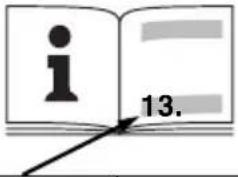 | STEB 65 Quick*1) Serial-Number: 01030.. | |
| M Nm (ihlbs) 4,4 (39) | ||
| T1 | mm (in) | 65 (2 ^3/_4 ) |
| T2 | mm (in) | 18 ^3/_4 |
| T3 | mm (in) | 6 ^1/_4 |
| n0 | min ^-1 (rpm) | 600 - 3000 |
| P1 | W 450 | |
| P2 | W 230 | |
| m kg (lbs) 1,9 (4.2) | ||
| ah,CM/Kh,CM | m/s ^2 | 8 / 1,5 |
| ah,Cw/Kh,Cw | m/s ^2 | 11 / 1,5 |
| LpA/KpA | dB(A) 85 / 3 | |
| LWA/KWA | dB(A) 98 / 3 | |

*2) 2014/30/EU, 2006/42/EC, 2011/65/EU
*3) EN 62841:2015, EN 62841-2-11:2016, EN 50581:2012
A
6.23591
10.
B
natural_image
Close-up of a melabo printer with a mechanical component and a separate 3D model showing internal structure (no text or symbols visible)10.
Original Instructions
1. Declaration of Conformity
We, being solely responsible: Hereby declare that these jigsaws, identified by type and serial number *1), meet all relevant requirements of directives *2) and standards *3). Technical documents for *4) - see page 3.
2. Specified Use
The machine is suitable for sawing non-ferrous metals and sheet steel, wood and similar materials, plastics and similar materials. Any other use is not permitted.
The user bears sole responsibility for any damage caused by inappropriate use.
Generally accepted accident prevention regulations and the enclosed safety information must be observed.
3. General Safety Instructions

For your own protection and for the protection of your electrical tool, pay attention to all parts of the text that are marked with this symbol!

WARNING – Reading the operating instructions will reduce the risk of injury.

WARNING – Read all safety warnings, instructions, illustrations and
specifications provided with this power tool.
Failure to follow all instructions listed below may result in electric shock, fire and/or serious injury.
Save all warnings and instructions for future reference. Pass on your electrical tool only together with these documents.
4. Special Safety Instructions
Hold the power tool by the insulated gripping surfaces when performing an operation where the cutting accessory may contact hidden wiring or its own cord. Contact with a live lead may also make metal power tool parts "live" and lead to an electric shock.
Using clamps or other means, fasten and secure the workpiece to a stable base. If you hold the workpiece only with your hand or against your body, it will remain unstable and this could lead to a loss of control.
Ensure that the place where you wish to work is free of power cables, gas lines or water pipes (e.g. check using a metal detector).
During work, the workpiece must lay flat and be secured against moving, e.g. using clamps.
Do not try to saw extremely small workpieces.
When sawing, the footplate must make secure contact with the workpiece.
When interrupting a cut for any reason, release the trigger and hold the saw motionless in the material until the saw blade comes to a complete stop. Never attempt to remove the saw from the workpiece while the saw blade is in motion or kickback may occur.
Do not switch the machine on while the saw blade is touching the workpiece. Let the saw blade reach full speed before making a cut.
When restarting a saw in the workpiece, centre the saw blade in the kerf and check that saw teeth are not engaged into the material. If the saw blade seizes, it may kickback from the workpiece when the saw is restarted.
Keep hands well away from the sawing area and the saw blade. Do not reach underneath the workpiece.
Remove chips and similar material only with the machine at a standstill.
Pull the plug out of the socket before making any adjustments, converting or servicing the machine.
Danger of injury due to the sharp jigsaw blade. After stopping work, the jigsaw blade may still be hot. Wear protective gloves.
Reducing dust exposure:

WARNING - Some dust created by power sanding, sawing, grinding, drilling, and other construction activities contains chemicals known to cause cancer, birth defects or other reproductive harm. Some examples of these chemicals are:
- Lead from lead-based paints,
- Crystalline silica from bricks and cement and other masonry products, and
- Arsenic and chromium from chemically treated lumber.
Your risk from these exposures varies, depending on how often you do this type of work. To reduce your exposure to these chemicals: work in a well ventilated area, and work with approved safety equipment, such as those dust masks that are specially designed to filter out microscopic particles.
This also applies to dust from other materials such as some timber types (like oak or beech dust), metals, asbestos. Other known diseases are e.g. allergic reactions, respiratory diseases. Do not let dust enter the body.
Observe the relevant guidelines and national regulations for your material, staff, application and place of application (e.g. occupational health and safety regulations, disposal).
Collect the particles generated at the source, avoid deposits in the surrounding area.
Use suitable accessories for special work. In this way, fewer particles enter the environment in an uncontrolled manner.
Use a suitable extraction unit.
Reduce dust exposure with the following measures:
- do not direct the escaping particles and the exhaust air stream at yourself or nearby persons or on dust deposits,
ENGLISHen
- use an extraction unit and/or air purifiers,
- ensure good ventilation of the workplace and keep clean using a vacuum cleaner. Sweeping or blowing stirs up dust.
- Vacuum or wash the protective clothing. Do not blow, beat or brush.
5. Overview
See page 2.
1 Clamping lever for securing the saw blade
2 Saw blade support roller
3 Saw blade (with lock-in shank (T-shank))*
4 Screw for adjusting the foot
5 Footplate
6 Adjustment lever for pendulum motion
7 Anti-splintering footplate insert *
8 Saw blade clamping fixture
9 Protective rod for preventing unintentional contact with the saw blade
10 Protective cap
11 Setting wheel for speed adjustment
12 Trigger switch
13 Locking button for continuous activation
14 Handle
15 Extractor connection piece
16 Wrench depot
17 Hexagon spanner
18 Curved support plate indicating preset cutting angle
* depending on equipment/not in scope of delivery
6. Commissioning

Before plugging in, check that the rated mains voltage and mains frequency, as stated on the plate match your power supply.

Always install an RCD with a maximum trip current of 30 mA upstream.

Never operate the machine without a saw blade.

Pull the plug out of the socket before making any adjustments, changing tools, carrying out tenance or cleaning.
6.1 Fitting the anti-splintering footplate insert

Danger of injury due to the sharp jigsaw blade. Remove the saw blade before fitting the anti-tering footplate insert (7).
Turn the machine over so that the footplate faces upwards. Insert the anti-splintering footplate from the front, while noting the following 2 items:
- The smooth side of the footplate points upward.
- The slot is facing to the rear (towards the mains cable).
If you are working with the protective plate attached, fit the anti-splintering footplate insert in the protective plate.
6.2 Inserting the saw blade

Danger of injury due to the sharp jigsaw blade. After stopping work, the jigsaw blade may still not. Wear protective gloves.
Use a saw blade that is suitable for the material being sawn.
- Push the protective cap (10) upward.
- Turn the clamping lever (1) forwards to the stop and hold in place.
- Insert the saw blade (3) up to the stop. Ensure that the saw teeth are facing forwards and the blade is seated correctly in the groove on the saw blade support roller (2).
Release the clamping lever (1). (It returns to its initial position by itself. The saw blade is now securely tightened).
6.3 Sawing with dust extraction
- Connect a suitable extraction device to the extractor connection piece (15).
- For optimum dust extraction performance, push the protective cap (10) downward.
6.4 Sawing without dust extraction
- Work with the protective cap (10) pushed up.
6.5 Diagonal cuts
Push protective cap (10) upward.
Remove anti-splintering footplate (7) and extraction hose. These parts cannot be used for diagonal cuts.
- Slacken the screw (4).
- Rotate footplate (5).
- The preset angle is indicated on the curved support plate (18) on the footplate. Adjust to different angles using an angle gage.
- Tighten the screw (4) again.
6.6 Sawing close to the wall
Remove the protective cap (10), anti-splintering footplate insert (7), circular-cutting and parallel guide. These parts cannot be used when sawing close to the wall.
- Slacken the screw (4) until the footplate (5) can be raised slightly.
- Raise the footplate (5) slightly and slide backwards up to the stop.
- Tighten the screw (4) again.
7. Use
7.1 Adjusting the pendulum motion
Set the required pendulum motion using the adjustment lever (6).
Position "0" = pendulum motion is switched off ...
Position "III" = maximum pendulum motion See page 3 for recommend setting values.
The best way to determine the ideal setting is through a practical trial.
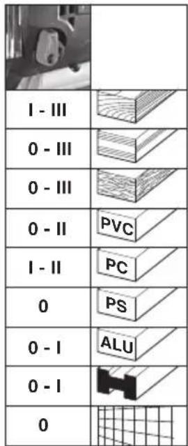
7.2 Setting maximum speed
Set the machine to maximum speed using the setting wheel (11). This can also be done during operation.
See page 3 for recommend setting values.
The best way to determine the ideal setting is through a practical trial.
7.3 On/Off switch, continuous activation
On: Press the trigger switch (12).
Off: Release the trigger switch (12).
Continuous operation: The trigger switch (12) can be locked using the lock button (13) for continuous operation. Press the trigger switch (12) again to stop the machine.

In continuous operation, the machine continues running if it is forced out of your
hands. Therefore always hold the machine with both hands using the handle provided, stand securely and concentrate.
8. Cleaning, Maintenance
Clean the machine regularly. This includes vacuum cleaning the ventilation louvres on the motor.
Clean the saw blade clamping fixture regularly and thoroughly by blowing with compressed air.
If necessary, clean the openings behind the saw blade support roller (2).
Apply a drop of oil to the saw blade support roller (2) from time to time.
9. Tips and Tricks
Plunging
The jigsaw blade can plunge into workpieces made from thin, soft materials without the necessity of drilling a hole beforehand. Only use short saw blades. Only at 0^ angle setting.
See illustration on page 2. Set the adjustment lever (6) to the "0" position (pendulum motion is deactivated). Position the jigsaw with the front edge of the footplate (5) on the workpiece. Hold the operating jigsaw firmly and guide slowly downwards. Once the saw blade has penetrated the workpiece, the pendulum motion can be activated.
In thicker workpieces, a hole for inserting the saw blade must be drilled first.
10. Accessories
Use only genuine Metabo accessories.
Use only accessories which fulfil the requirements and specifications listed in these operating instructions.
Fit accessories securely. If the machine is operated in a holder: Secure the machine well. Loss of control can cause personal injury.
See page 4.
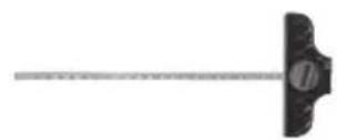
A Circular-cutting and parallel guide
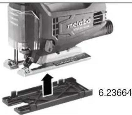
B Protective plate (prevents workpieces with sensitive surfaces from becoming scratched)
10.1 Attaching the circular-cutting and parallel guide
For sawing circles (dia. 100 - 360 mm) and making cuts parallel with edges (max. 210 mm).
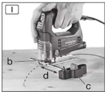
Attach circular guide (see Fig. I)
- Slide the rod on the circular-cutting and parallel guide sideways into the footplate (centre point (c) faces downwards).
- Set the desired radius (d).
- Tighten screw (b).
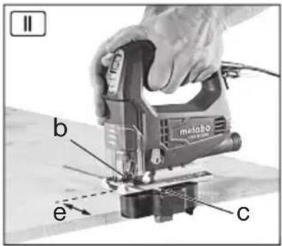
Attach parallel guide (see Fig. II)
- Slide the rod on the circular cutting and parallel guide sideways into the footplate (the centre point (c) faces upwards).
- Set the dimension (e)
- Tighten screw (b).
In order to minimise saw blade drifting, we recommend using extra-thick saw blades: 6.23694, 6.23679, 6.23685
See www.metabo.com or the catalogue for a complete range of accessories.
11. Repairs

Repairs to electrical tools must ONLY be carried out by qualified electricians!
A defective mains cable must only be replaced with a special, original mains cable from metabo, which is available only from the Metabo service.
Contact your local Metabo representative if you have Metabo power tools requiring repairs. See www.metabo.com for addresses.
You can download a list of spare parts from www.metabo.com.
12. Environmental Protection
Observe national regulations on environmentally compatible disposal and on the recycling of disused machines, packaging and accessories.

Only for EU countries: Never dispose of power tools in your household waste! In accordance with European Directive 2012/
19/EU on used electronic and electric equipment and its implementation in national legal systems, used power tools must be collected separately and handed in for environmentally compatible recycling.
13. Technical Data
Explanatory notes on the specifications on page 3. Changes due to technological progress reserved.
M = T o r q u e
T_1 =Maximum material thickness in wood
T_2 =Maximum material thickness in non-ferrous metals
T_3 =Maximum material thickness in sheet steel
ENGLISHen
n_0 =Stroke rate at idle speed
P_1 =Rated input power
P_2 =Power output
m=Weight without mains cable
Measured values determined in conformity with
EN 60745.
□ Machine in protection class II
\~ AC Power
The technical specifications quoted are subject to tolerances (in compliance with the relevant valid standards).
Emission values These values mak
These values make it possible to assess the emissions from the power tool and to compare different power tools. The actual load may be higher or lower depending on the operating conditions, the condition of the power tool or the accessories.
Please allow for breaks and periods when the load is lower for assessment purposes. Arrange protective measures for the user e.g. organisational measures based on the adjusted estimates.
Vibration total value (vector sum of three directions) determined in accordance with EN 60745:
a_h,CM =Vibration emission value (Sawing sheet metal)
a_h,CW =Vibration emission value (Sawing wood)
K_h, = Uncertainty (vibration)
Typical A-effective perceived sound levels:
L_pA =sound-pressure level
L_WA^' = Acoustic power level
K_pA , K_WA= Uncertainty

Notice originale
K_h, = incertitude (vibration)
L_pA =äänen painetaso
L_WA =äänen tehotaso
5. Lüphwünp gllwpwqpnlpynl6
Shu 12 2:
1 9qh2 l8ml' ungh ckpp mfpmgfikm hundmp
2 Uqngh chqph hkfgmhnlmwl
3 Uqngmcknp (ukl hklmlqn] uqnsmufmmnl (T-ah uqnsmufmm)) ^*
6.1 Smcthg wquwqfinn umlhh wkwnppmf

Uqagh unip elnpanl hmpuludf unuufwunc jnuuq: Swelnhg uquemwufing uu|hlp unlqnwnplhu (7) clnpp utknf t hwfuud jhi:
Fupdhp upunkf uyfuqlu, npwluqh hldfmpuqp qluqh dlpl Gujh: Swckhg npwunuwufn uwwlhp mkquwpl wngzhg, ncuwnpncpjnli npudljl 2 qnpdnhlpph dlpu
• Uwlhlh hwpb bptun qthgh qnpu qhpfnl E:
• Φnpwhp hwlqwnwh mηηηρjωφε ε (uθmιgδωδ δωλmιψh nηηηρjωφε):
Gpt wchwnnul bf uwcunuwghs ywhwfinl, uww wtqnwnptf unwctnhg uwcunuwghs uwllhpr ywhwgh utg
6.2 Uqngwcknph inkwnppnui

Uqngh unip ctnpnl lqnpjwdf uwwgwnl qnwfg: Uppnnnqh ctnpnl ungklng hwnn lqpmn t mdtn guj: Ypl'f wuewnuqihy ahting:
Oqunwqnptbf dcwllqlnq gjnlph hwdwp hwdwwwnwnwulw6nn uynngmctnp:
The text in the source image is illegible due to extreme low resolution and noise. No characters, punctuation, or structure can be reliably extracted. Therefore, no valid OCR text can be generated that matches the visual content of the source image.
[1]
^1 ^2 ^3
_p2m1m1h m1n1n1n1h1 m1n1n1n1 (m1n1n1n1)
13. Slphghwqng pinnpwqhp
Qupqupwlnlukp 3- h upw uplud wjlwltph ytpwpptjwl:
tGpwLw L ylnhnlouwG wtlyghlqwLwG pwptlwylwG Guqwnwnlqnl:
M = Φ_{www} ∫n∫t6m
T_1 =_jnlph wnwnlglwqnljg hwwunnlpjnliq ihwjnh hwuwp
T_2 =_jmph wnmylbLwqmj6 hwnwnmpjm6 qnl6wmlp uftwnwnl hwndp
T_3 =_jnlphwnnwjlqwnlgi hwwnnnlpjnlig pbppwwqnqnqwwnh hwufwp
n0 =φwjltplh fwglwlL wwpww L Gpwgf h dmflwglh
P_1 =U.GyM6wLqM6 yBpgyJn hqnpmPjmG
P_2^' =S_p|n|qh_q|p|q|p|m|f
m^-=_mc mmfg ufingdmf lmph
9amphh shwlpfkp pum EN 62841 fnpdh:
□ 9nphf wmcwnw6mprjml ll qnuh
\~ Φημηρωμημή hνυμή
Lclmd wt lvghlqlmg wylmLgtpp m6t6 pmjLwnptl ckpnufktp (hwdmqnwnwnlomf qnpdnq wnmfhpmpufktph) :

Upuuugtumui6tpj wpdtf6tp
Leymd wpdtfikp hqimpywup hgmpwnnp l unmwwnl h hmultmuntl mju qnpdhfmj h wjl qnpdhfikpmj mcvmwnnfgh plonn wpmmftknnufikph fuftmhfikpp: Lum lhpwnufml uqwduwiflph, qnpdhfi djhfuulh l lhpwnufan wpmpuquwfliph' daqhafvjnlü, üldwunuf lhw fijwqnü l qhuunugh wpmmftknnufikph fuftwlp: Zwejwplh dwduwulh hwclh untf pfipdhqnuifikpp h gmdp ptufdmndprjmbi mcvmwnnfwjhi fhuyltpp: Unmwnlp wpdtfikp unmwfnug htunn oqmuqnpdnqh hwnfup alnfuuphl f huudwnwnwnuwuli wucnnuwihz ahyngfip fuw hwaqduwlpuyswuhui ahyngfip:
_mmh_mu_hh_kp_h_hh_mu_mp_wd_hf_pq_hl_mn_mp_wu_hf_kq_wd_wu_p' h_mu_mu_nu_hf_kEN 62841 l_mu_h.
a_h,CM = _ppnnulliph mplhf (U^knnwnwphpph uqngnul)
a_h,CW = ppnnlufthwpdtf (qwnjnh wqngnl) Kh, = U_fllqujnlfnlpjnli(S_mmwlnlufllp)
Uqunlgh A-nwh whhly dwlwnqwl:
L_pA = U_lqnnwnhl Gc wG wLwPnWl
L_WA = U_qnlnlh hqnpnlpjwfi dwhwpnwlq
K_pA, K_WA=S_wwwfinlif

Skqhlnpynli qfinpph hwnup.
Zmifuuqmmuujwfiipjwi huihmmqqhp No EA3C N RU C-
DE.ΓБ09.B.00165/20, qnpδnlu L ulquwδ 23.03.2020
22.03.2025 pp., mpylt L «Ubqwllhu|wjw
fumtpunhqm UQF, wpwnqnq6f, hwnwnwnqnq6dmp6h
lnqihg, huugk (hpwlwplwlquli li qnpdnliknlpjuli)


- Original Instructions
- Declaration of Conformity
- Specified Use
- General Safety Instructions
- Special Safety Instructions
- Reducing dust exposure:
- ENGLISHen
- Overview
- Commissioning
- Fitting the anti-splintering footplate insert
- Inserting the saw blade
- Sawing with dust extraction
- Sawing without dust extraction
- Diagonal cuts
- Sawing close to the wall
- Use
- Adjusting the pendulum motion
- Setting maximum speed
- On/Off switch, continuous activation
- Cleaning, Maintenance
- Tips and Tricks
- Plunging
- Accessories
- Attaching the circular-cutting and parallel guide
- Repairs
- Environmental Protection
- Technical Data
- Emission values These values mak
- Notice originale
- Lüphwünp gllwpwqpnlpynl6
- Smcthg wquwqfinn umlhh wkwnppmf
- Uqngwcknph inkwnppnui
- Slphghwqng pinnpwqhp
- Upuuugtumui6tpj wpdtf6tp
Brand : METABO
Model : STEB 65 Quick
Category : Saw