
4 Series Classic LS Plus - Barbecue CAMPINGAZ - Free user manual and instructions
Find the device manual for free 4 Series Classic LS Plus CAMPINGAZ in PDF.
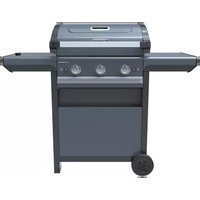
| Product type | Gas barbecue |
| Brand | Campingaz |
| Model | 4 Series Classic LS Plus |
| Number of burners | 4 |
| Fuel | Butane/propane gas, bottle 4.5-15 kg, appropriate regulator (28-50 mbar depending on country) |
| Burner material | Steel or cast iron depending on model |
| Ignition system | Piezoelectric or electronic spark |
| Cooking system | Removable Culinary Modular center grate, enameled grills and plates |
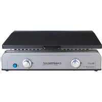
| Special features | InstaClean (dishwasher-safe removable tank), side burner (depending on model), console lighting (depending on model) |
| Maintenance | Burners cleanable with brush, tank and grease drawer dishwasher-safe |
| Safety | Outdoor use only, 60 cm clearance from combustible materials, mandatory leak test |
| Optional accessories | Pizza stone, wok, paella pan Culinary Modular, protective cover |
| Batteries | 4 AA batteries (LR06) for lighting (if equipped) |
| Storage | Disconnect the bottle, store in a sheltered place, use a cover |
Frequently Asked Questions - 4 Series Classic LS Plus CAMPINGAZ
User questions about 4 Series Classic LS Plus CAMPINGAZ
0 question about this device. Answer the ones you know or ask your own.
Ask a new question about this device
Download the instructions for your Barbecue in PDF format for free! Find your manual 4 Series Classic LS Plus - CAMPINGAZ and take your electronic device back in hand. On this page are published all the documents necessary for the use of your device. 4 Series Classic LS Plus by CAMPINGAZ.
USER MANUAL 4 Series Classic LS Plus CAMPINGAZ
natural_image
Two mechanical components with arrows indicating assembly or movement, no visible text or symbolsnatural_image
Illustration of a gas cylinder connected to a portable gas station with a smiley face indicator (no text or symbols)(selon modèle)
(selon modèle)
FR
natural_image
Technical diagram of a portable stove with internal components and heat exchanger (no text or symbols)natural_image
3D mechanical component diagrams showing two views of a device with labeled parts (no text or symbols present)

natural_image
Three different metal grate structures shown from different angles (front, side, and top) with no visible text or symbols.natural_image
3D diagram of a grid-patterned plate with an oval cutout and an arrow pointing to it (no text or symbols)Bois :
natural_image
Two circular metal grates on a square base, one lid partially filled with a grid pattern (no text or symbols visible)Operation and maintenance
GB

NOTE: Unless otherwise specified, following generic terms “appliance / unit / product / equipment / device” appeared in this instruction manual all refer to the product “3 & 4 series classic & woody”.
- Please read the instructions carefully before using.
- Use outdoors only
- It is best to wear gloves to assemble the product.
- Do not use charcoal.
- Do not use an adjustable low pressure regulator. Use fixed regulators that comply with the European standard concerning them.
• To ensure safe operation of your device, never use two full hot plates side by side.
- Regularly clean the parts at the frame bottom to avoid risk of inflammation from fat drippings.
Follow these instructions carefully to avoid seriously damaging your barbecue.
a) FOR YOUR SAFETY
- Do not store or use petrol and other flammable liquids or vapours in the vicinity of this barbecue. This device must be kept away from inflammable materials when it is in use. If you smell gas:
1) Close the valve of the cylinder
2) Extinguish all naked flames
3) Open the lid
4) If the smell continues, see "f Checking for gas leaks" or immediately seek advice from your local retailer.
- Parts which are protected by the manufacturer or the manufacturer's representative must not be manipulated by the user.
- Close the gas container after use.
b) LOCATION
- This barbecue must only be used outdoors.
- CAUTIOUS: accessible parts may get very hot. Keep young children away.
- There should be no combustible materials within a radius of approximately 60 cm around the barbecue
- Do not move the barbecue when alight.
- The appliance should be operated on a level surface.
- Estimated air offtake 2 m³/kW/h.
c) GAS CYLINDER
This barbecue has been adjusted to operate either from 4,5 to 15 kg butane/propane cylinders with an appropriate low pressure regulator:
- France, Belgium, Luxembourg, United Kingdom, Ireland, Portugal, Spain, Italy, Greece : butane 28 mbar / propane 37 mbar.
- Netherlands, Czech Republic, Slovakia, Hungary, Slovenia, Norway, Sweden, Denmark, Finland, Switzerland, Bulgaria, Turkey, Romania, Croatia: butane 30 mbar / propane 30 mbar.
- Poland: propane 37 mbar.
- Germany, Austria: butane 50 mbar / propane 50 mbar.
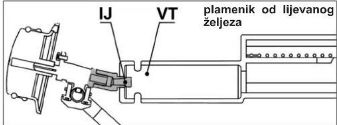
Always connect or replace the cylinder in a well-ventilated area, never in the presence of a flame, spark or heat source.
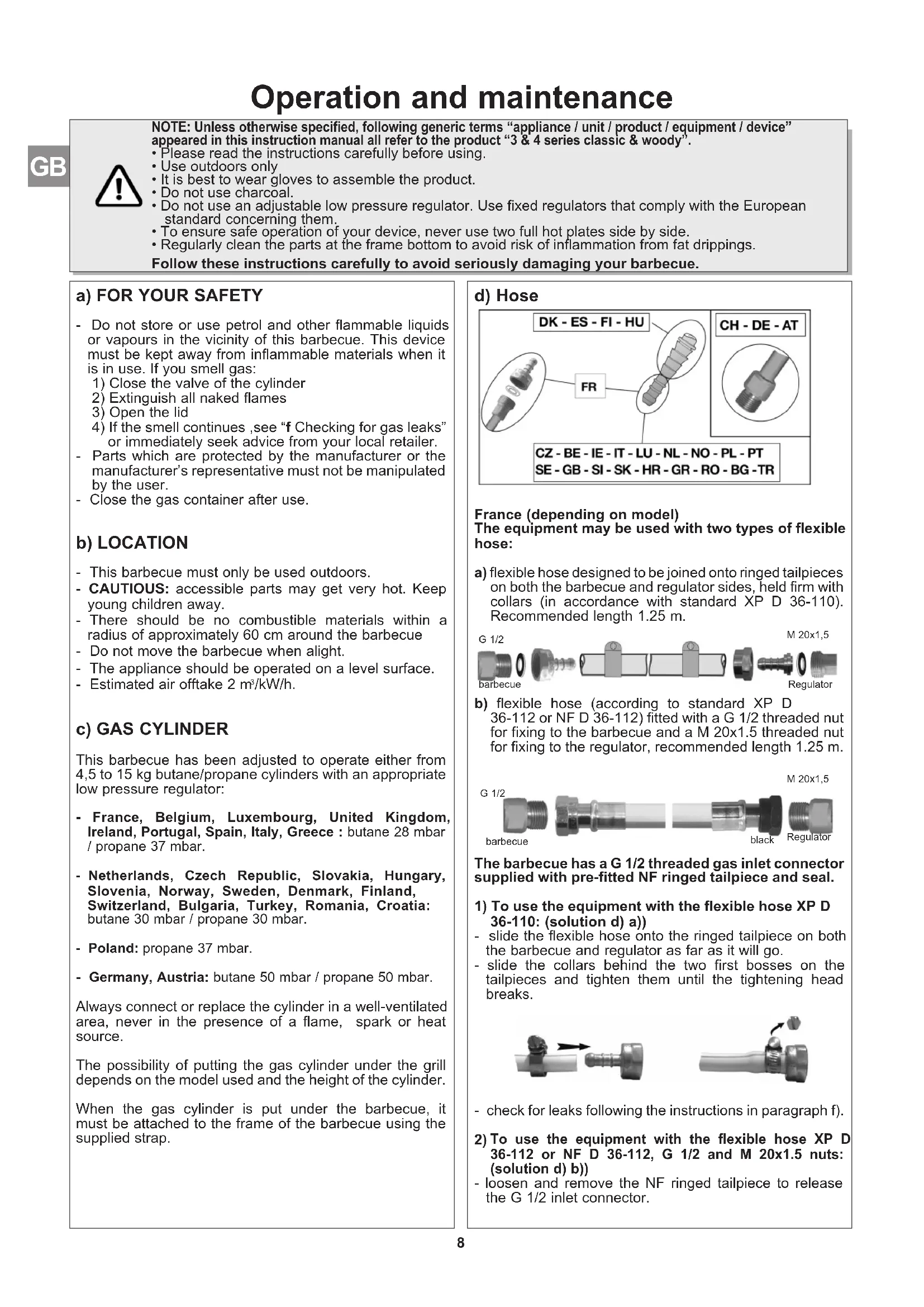
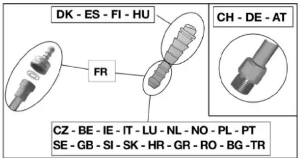
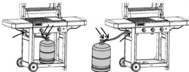
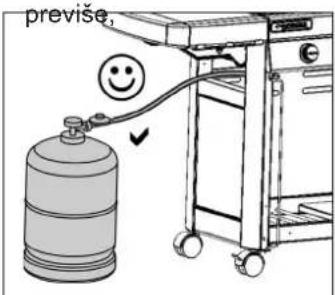
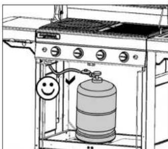
The possibility of putting the gas cylinder under the grill depends on the model used and the height of the cylinder.
When the gas cylinder is put under the barbecue, it must be attached to the frame of the barbecue using the supplied strap.
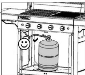
d) Hose
France (depending on model)
The equipment may be used with two types of flexible hose:
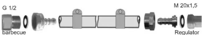
a) flexible hose designed to be joined onto ringed tailpieces on both the barbecue and regulator sides, held firm with collars (in accordance with standard XP D 36-110). Recommended length 1.25 m.
b) flexible hose (according to standard XP D 36-112 or NF D 36-112) fitted with a G 1/2 threaded nut for fixing to the barbecue and a M 20x1.5 threaded nut for fixing to the regulator, recommended length 1.25 m.
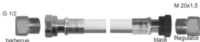
The barbecue has a G 1/2 threaded gas inlet connector supplied with pre-fitted NF ringed tailpiece and seal.
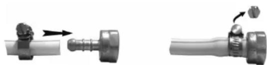
1) To use the equipment with the flexible hose XP D 36-110: (solution d) a))
- slide the flexible hose onto the ringed tailpiece on both the barbecue and regulator as far as it will go.
- slide the collars behind the two first bosses on the tailpieces and tighten them until the tightening head breaks.
natural_image
Two mechanical components with arrows indicating motion, one showing a valve and the other a handle (no text or symbols visible)- check for leaks following the instructions in paragraph f).
2) To use the equipment with the flexible hose XP D 36-112 or NF D 36-112, G 1/2 and M 20x1.5 nuts: (solution d) b)) - loosen and remove the NF ringed tailpiece to release the G 1/2 inlet connector.
- remove the seal
- tighten the G 1/2 threaded nut on the hose onto the barbecue inlet connector and the M20x1.5 threaded nut onto the regulator output connector following the instructions supplied with the flexible hose.
- use a spanner to hold the barbecue inlet connector firm and tighten or loosen the threaded nut with another spanner.
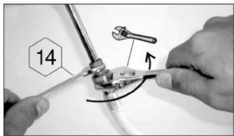
- use a spanner to hold the regulator outlet connector firm.
- check for leaks following the instructions in paragraph f).
Check that the flexible hose stretches out normally without twisting or pulling and does not come into contact with the hot sides of the barbecue. It should be replaced when the expiry date on the hose is passed or whenever it is damaged or develops surface cracks.
Belgium, Luxembourg, United Kingdom, Ireland, Portugal, Spain, Italy, Croatia, Greece, Netherlands, Czech Republic, Slovakia, Hungary, Slovenia, Norway, Sweden, Denmark, Finland, Bulgaria, Turkey, Romania, Poland:
The barbecue is equipped with a circular should be used with flexible hose that is suitable for use with butane and propane gas. Hose length should not exceed 1.20 metre. It should be replaced if it is damaged or cracked, when required by national regulations or at the end of the part lifecycle. Do not pull or pierce the hose. Keep away from any parts of the barbecue that get hot. Check that the flexible hose stretches out normally, without twisting or pulling.
Switzerland, Germany, Austria:
The barbecue should be used with flexible tubing that is suitable for use with butane and propane gas. Hose length should not exceed 1.50 metre. It sh replaced if it is damaged or cracked, when required by national regulations or at the end of the part lifecycle. Do not pull or pierce the tubing. Keep away from any parts of the barbecue that get hot. Check that the flexible hose stretches out normally, without twisting or pulling.
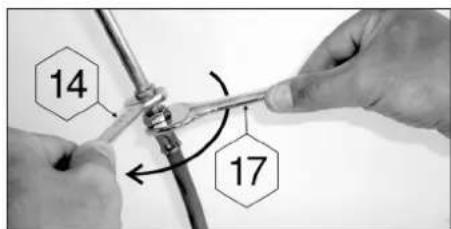
Flexible tubing connection: to connect the tubing to the connector on the barbecue, tighten the nut on the tubing firmly but without excess force using the two wrenches provided:
- no. 14 wrench to tighten the connector - no. 17 wrench to tighten the nut on the tubing
e) LID
Handle the lid carefully, especially during operation. Do not lean over the base.
f) CHECKING FOR GAS LEAKS
1) Work outside, away from all sources of ignition. Do not smoke.
2) Make sure the control knobs are in the "off" (O) position.
3) Connect the flexible tubing to the connector and barbecue as described in part d).
4) Fit the regulator onto the gas cylinder in accordance with its instructions.
5) Use a gas leak solution to test for leaks. Important: never use a naked flame to check for gas leaks.
6) Apply the solution to the connections cylinder/regulator/hose/apparatus (the control knobs should remain closed: off position (O)). Open the gas cylinder valve.
natural_image
Two identical line drawings of a gas stove with a cylindrical tank, connected by tubing to a gas cylinder (no text or symbols present)7) Bubbles in the gas leak solution indicate that there are gas leaks.
8) The leak can be stopped by tightening any hose connection or replacing any faulty component. The barbecue must not be used until the leak is stopped.
9) Close the valve on the gas cylinder.
Important:
Check for leaks at least once per year and each time the gas cylinder is replaced.
PRIOR TO USE
Never use the barbecue until the instructions have been read carefully and understood. Also, make certain that:
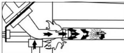
- there are no leaks
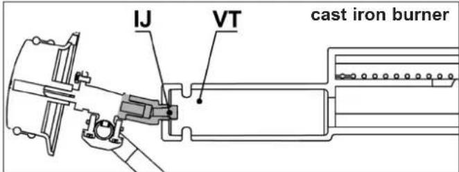
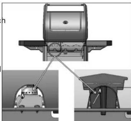
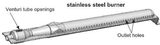
- the venturi tubes are not blocked (example: spider webs)
natural_image
Pure mechanical diagram showing a lever mechanism with arrows and gear symbols (no text or labels)d be
- the hose does not touch any components which may get hot.

natural_image
Illustration of a gas cylinder connected to a cart via a piping bag with a smiley face (no text or symbols)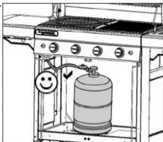
natural_image
Line drawing of a gas stove with a water dispenser and a smiley face indicator (no text or symbols)that the ventilation openings in the gas receptacle housing are not obstructed, if appropriate.
- that the grease trap(s) is (are) correctly inserted into its (their) compartment and that it (they) is (are) correctly positioned, as far as it (they) will go.
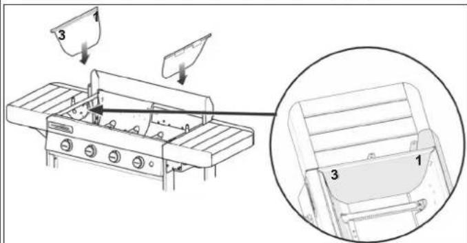
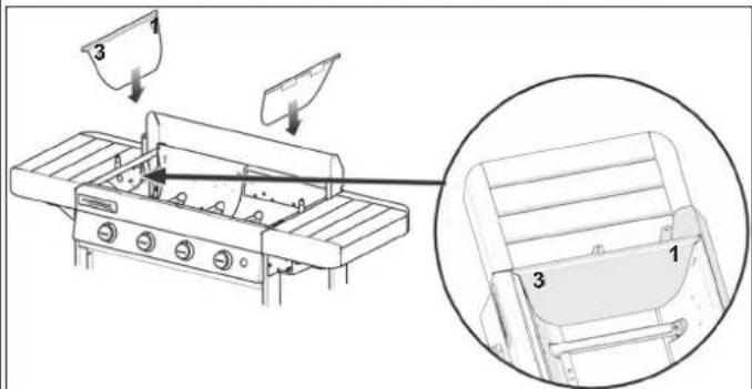
- that the 6 removable parts of the firebox enclosure are put back in place (see paragraph p) Cleaning and maintenance)

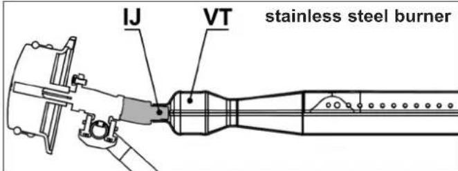
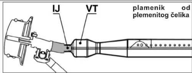
Check that the venturi tubes (VT) cover the injectors (IJ).
- Open the cooking lid.
- Make sure that the control knobs are in the "OFF" position (O).
- Press and turn the adjustment lever counter-clockwise and put it in a full flow position (⚡️).
If your barbecue grill is equipped with a piezoelectric igniter:
- Press immediately on the igniter button (⚡) until it clicks.
- If the burner does not ignite after 4 or 5 attempts, wait 5 minutes and then repeat the operation.
If your barbecue grill is equipped with an electronic spark igniter:
- Press immediately on the switch ( ). A burst of sparks occurs. Continue pressing for a few seconds until the burner is lit.
- If the burner does not ignite after 4 or 5 attempts, wait 5 minutes and then repeat the operation.
Once the burner is lit, there are two ways of lighting another burner:
- Firstly, repeat the lighting operation described above;
- Secondly, light the burner to the right or left of the first burner lit, then the other burners in turn by turning the adjustment button to the full flow position (4)
If the piezoelectric ignition or the electronic ignition doesn't work, use the manual ignition (following paragraph).
- Open the cooking lid.
- Make sure that the control knobs are in the "OFF" position (O).
- Light a match and then bring it from the back of the barbecue grill toward the burner
- Push the control knob in and turn it anticlockwise until it is in the full flow position (
natural_image
Technical diagram showing mechanical assembly with labeled components and connection arrows (no readable text or symbols)burner
stainless steel
cast iron burner
Return the control knobs to the "off" position (O), then close the cylinder valve.
(depending on the model)
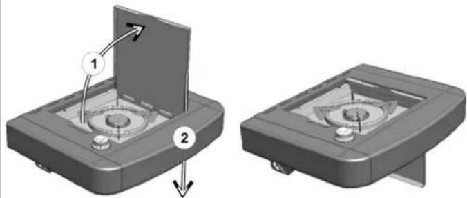
The stove may operate independently or in conjunction with the grill burner. Before igniting the camping stove, be sure that the lid is open and then flipped away.
natural_image
Two 3D mechanical components with arrows indicating assembly or transformation, no visible text or symbolsLighting:
- open the gas cylinder valve.
- check that there is no gas leak between the gas cylinder and the stove.
- check the condition of the hose connecting the grill burner to the stove. If there are signs of cracks, call our After Sales Service to have it replaced.
- Open the valve of the camping stove (+ direction).
- If your barbecue grill is equipped with a piezoelectric igniter:
Press on the igniter button located to the right of the control panel and identified in the pictogram (⚡️) until it clicks. Press 3 or 4 times if necessary.
- If your barbecue grill is equipped with an electronic spark igniter:
Press immediately on the switch ( ) A burst of sparks occurs. Continue pressing for a few seconds until the burner is lit.
- Should the stove fail to light, present a match to the edge of the burner.
- Adjust the size of the flame to the dimensions of the container you are using by opening the valve to various extents. Do not use a container smaller than 12 cm or larger than 24 cm.
(depending on the model)
Close the stove valve (towards the -) and close the valve of the gas cylinder if the grill burner is not in use.
M) Lighting of the console
(depending on the model)
The lighting system of the console is powered by 4 type AA (LR06) batteries provided with the barbecue grill. The battery holder box is located on the front left support, behind the left door. Remove the cover of the battery holder box by sliding it upwards. Insert the batteries while respecting the polarities indicated and then replace the cover.
To turn the lighting on or off, press on the stop-start button located to the left of the console and identified by this pictogram.

n) REPLACING THE GAS CYLINDER
- Always work in a well ventilated area and never in the presence of a flame, spark or heat source.
- Return the control knobs to the "OFF" position (O) then close the cylinder valve.
- Remove the regulator, check that the sealing joint is in good condition.
- Put the full cylinder in place, refit the regulator, taking care not to apply stress to the hose. Check for gas leaks.
o) OPERATION
When used for the first time, heat up the barbecue (close the cooking lid) with its burners in full on position ( ♦ ), for approximately 30 minutes in order to eliminate any odors resulting from the paint on the new parts.
It's recommended that protective gloves be worn to handle components which may be very hot. In normal operation, preheat the barbecue for minutes to bring the grills to a good cooking temperature.
Cooking speed can be regulated via the adjustment buttons: between the full flow position (⚡️) and medium flow position (◀️).
In order to reduce food from sticking to the grilles, brush the grilles lightly with cooking oil prior to placing any food to be grilled.
To cook fatty meats while avoiding rising flames, you must generally cook at a reduced rate, even turning off one or more burners for a few minutes if necessary.
In order to reduce the amount of grease catching fire while cooking, remove any surplus fat from the meet prior to placing it on the grille. Clean the barbecue after each use to prevent the accumulation of grease and the risk of it catching fire.
Depending on the models, your barbecue grill may be equipped with a cast iron cooking plate. This plate has a double cooking face: one ribbed face permitting the searing of meats and one smooth face for the cooking of fish, shellfish, vegetables, etc...
Important: If one or several burners go out whilst you are using the barbecue, move the adjustment buttons to OFF immediately (O). Wait five minutes to allow the unburned gas to escape. Only carry out the lighting steps after this time.
- Never modify the barbecue: any modification may prove dangerous.
- In order to maintain your barbecue in perfect operating condition, it is recommended to clean it periodically (after 4 or 5 uses).
- Wait until the barbecue has cooled down before cleaning.
- Close the gas cylinder.
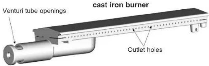
- The grill burner must be cleaned and checked every 3 months. Remove the entire burner and check that no dirt or spider webs block the venturi tube openings, which may cause the burner to be less efficient or cause a dangerous gas fire outside the burner.
- Clean the top of the burner, as well as the sides and base, using a moist sponge (water with washing up liquid). If necessary, use a damp steel brush.
- Check that all burner outlets are clear and let dry before using again. If necessary, use a wire brush to unclog the burner outlets.
- Refit the grill burner correctly.
- Clean the orifices on the Venturi jet (see diagram below) or the burner if necessary.
N.B.: Frequent cleaning of the burner maintains it in good condition for many uses and prevents premature oxidation, notably due to acid residue from cooking. Oxidation of the grill burner is, however, normal.
a few
Control panel
Clean these elements from time to time using a sponge with washing up liquid. Do not use abrasive products.
Firebox wall
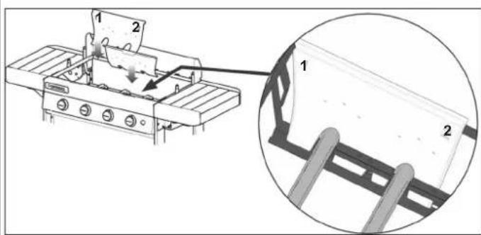
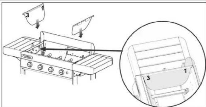
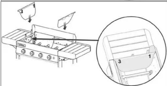
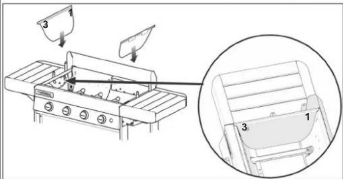
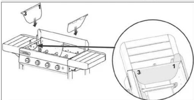
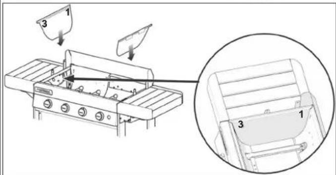
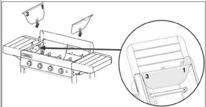
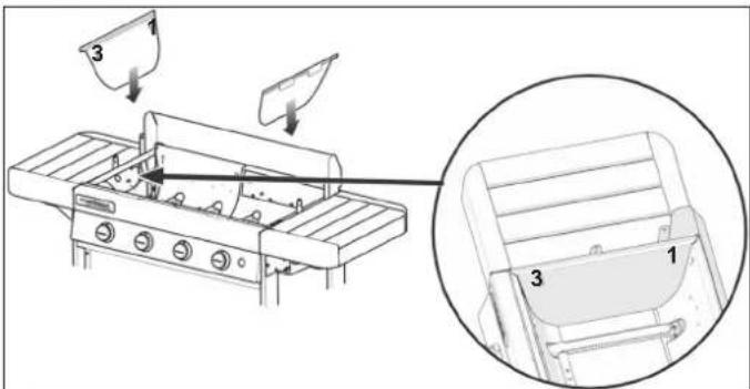
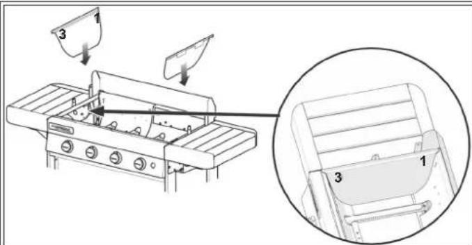
To facilitate the cleaning of the firebox wall, Campingaz ^® has invented Campingaz InstaClean ^™ , the concept of the removable firebox. Thanks to Campingaz InstaClean ^™ , all of the parts of the tank are removable, without using a tool, in under one minute, and can be washed in a dishwasher.
Depending on to the degree of dirtiness of these parts, it may be necessary to brush the parts before putting them into the dishwasher for a more complete cleaning.
For the assembly and removal of these parts, refer to the assembly manual.
For reassembly after cleaning, put the first 2 walls numbered "1-2" in first, and then the walls numbered "2-3", and finally the 2 side walls numbered "3-1".

GB
Grease collection tray
Depending on the model, your barbecue grill is equipped with one or two grease collection trays. It is recommended that you clean it (them) after each use. It (they) can be washed in the dishwasher.
To ease the cleaning, the width of the grease collecting trays are sized to permit covering them with a piece of aluminium foil, able to be purchased in stores, before putting the barbecue grill into operation. After use of the barbecue grill, discard the aluminium foil.
It is also possible to put a bit of sand the grease collection tray, which will absorb the cooking grease. Discard the sand after each cooking period.
Cooking plate and grill
Your cooking plate and grill are enamelled.
Wait for them to cool before any cleaning operation. Use a Campingaz ^® BBQ Cleaner Spray cleaning product and brushes for barbecue grills.
You may clean your cooking plate and grill in the dishwasher. Before putting them into the dishwasher, it is often necessary to scrape them with a sponge or a metallic brush to remove residue that sticks to the cooking surface.
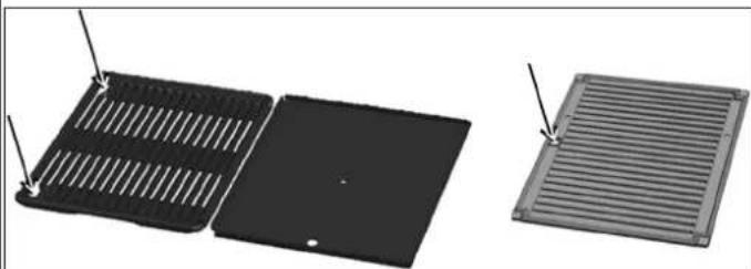
To remove the metal cooking plate and grill and the cast iron plate, slide your finger into the indicated holes, lift them and take hold of them with the other hand.
natural_image
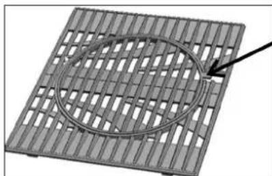
Three different types of ventilation grilles shown from different angles (no text or symbols visible)To remove the cast iron grill made of up 2 parts (see paragraph r) below), first remove the central portion with the help of the indicated tab, and then remove the contour.
natural_image
3D diagram of a grid-patterned plate with an oval cutout and an arrow pointing to it (no text or symbols)Wood (depending on the model)
In the concern of keeping its natural appeal protecting it, the wood of the barbecue grills is covered with protective oil. It is however a living room remains sensitive to exposure to the rays of the sun, humidity and changes in temperature.
To keep your barbecue looking as new, we recommend you cover it with a Campingaz® protective cover available as an accessory. Important: wait for the barbecue to cool down completely before putting on its protective cover. At the beginning of the season, apply a coat of lazure for exterior wood on the wooden parts with a rag or brush to give it a shinier appearance and keep it protected. Important:
At the beginning of the season, apply a coat of linseed oil or teak oil onto the wood parts with a rag or brush in order to give it a more brilliant appearance and to maintain its protection.
q) STORAGE
- Close the gas cylinder valve after use.
- If you store your barbecue indoors, disconnect the gas cylinder and store the cylinder outdoors.
- If you store your barbecue outdoors, it is recommended that a protective cover be used.
- When not used for a long period of time, it is recommended that the barbecue be stored in a dry, sheltered place (eg: garage).
- Environment conducive to corrosion: particular care must be taken with the product if used by the sea; it must not be stored outside without protection, and must be kept sheltered in a dry environment.
in r) ACCESSORIES the bottom of
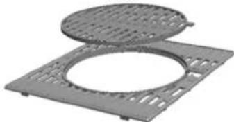
Depending on the model, your barbecue grill may be equipped with Campingaz® Culinary Modular grills. The Campingaz® Culinary Modular cooking grill is made up of 2 parts:
- the contour
- the centre.
natural_image
Two gray metal plates with circular cutouts and perforated bases, no text or symbols visible.The centre is removable and may be replaced by one of the accessories sold separately by Campingaz ^® , for example:
- Pizza stone
- Wok
- Paella plate
The Campingaz® Culinary Modular concept therefore allows you to transform your barbecue grill into a true outdoor kitchen and to use a specific cooking support depending on what you are preparing.
If your model of barbecue grill is not equipped Campingaz® Culinary Modular grills, you may purchase them separately.
ADG advises that its gas barbecues should systematically be used with accessories and replacement parts from Campingaz®. ADG accepts no responsibility for any damage or malfunction due to the use of accessories and/or replacement parts from other brands.
s) PROTECTING THE ENVIRONMENT
Think about protecting the environment! Your equipment contains materials which can be recovered or recycled. Hand them in to the waste collection service in your material, which municipality and sort the packing materials.
t) BATTERY RECOMMENDATIONS
This symbol found on the batteries means that at the end of their lives, the batteries must be removed from the unit, and then recycled or properly disposed of. The batteries should not be thrown into the trash, but should be brought to a collection point (dump...). Check with your local authorities. Never dispose of in nature, do not incinerate: the presence of certain
substances (Hg, Pb, Cd, Zn, Ni) in used batteries may be hazardous to the environment and human health.
u) ELECTRICAL AND ELECTRONIC WASTE
This symbol means that the appliance's electrical system must be disposed of selectively. At the

its life, the appliance's electrical system must be scrapped correctly. The electrical system must not be disposed of with unsorted municipal waste.
Selective collection of waste promotes reuse, recycling or other forms of recovery of recyclable materials contained
in this waste. Take the appliance's electrical system to a waste recovery centre designed for the purpose (waste collection point). Check with your local authorities. Never dispose of in nature, do not incinerate: the presence of certain hazardous substances in electrical and electronic equipment can be harmful to the environment, and have a potential effect on human health. end of
GB
| Problems | Probable causes / remedies |
| Burner won’t light | - Lack of gas supply- Regulator does not work- Hose, valve, jet, venturi tube or burner openings are blocked.- Venturi tube not seated over jet |
| Burner “pops” or blows itself out | - Check gas supply- Check hose connections- Contact the After Sale Service |
| Excessive flare-up | - Clean the protective plate above the burner.- Clean the grease drip tray- Grill temperature too high: lower flame |
| Burner lights with a match, but not with the “PIEZ” igniter | - Faulty igniter, wire o’electrode- Check igniter cable connections- Check condition of electrode and connection wire- Contact the After Sale Service |
| Problems | Probable causes / remedies |
| Fire at any connection | - Leaking connection- Turn off gas supply at cylinder immediately- Tighten connections and check for leaks- Contact After Sales Service |
| Incomplete flame around burner | - Defective or clogge burner: relocate the Venturi.- Clogged jets: clean the Venturi- Contact After Sales Service- Clogged jet or venturi tube- Contact After Sales Service |
| Lack of Heat | |
| Fire behind control knob | - Defective tap unit- Turn off gas supply at cylinder immediately- Contact After Sales Service |
| Fire under control panel | - Turn off gas supply at cylinder immediately- Contact After Sales Service |
USO E MANUTENZIONE
natural_image
Two mechanical components with arrows indicating motion, one showing a valve and the other a handle (no text or symbols visible)natural_image
Two identical line drawings of a gas stove with a cylinder inside, connected by tubing to a gas cylinder (no text or symbols present)natural_image
Pure mechanical diagram showing a lever mechanism with arrows indicating motion, no text or symbols presenth) ACCENSIONE DEL BRUCIATORE DEL BARBECUE
natural_image
Technical diagram of a mechanical device with exploded view and close-up views (no text or symbols)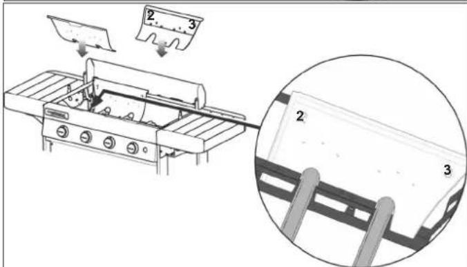
natural_image
Three different metal grate structures shown from different angles (no text or symbols visible)natural_image
3D diagram of a mesh grid with an elliptical cutout and an arrow pointing to it (no text or symbols)natural_image
Two gray metal plates with circular cutouts, one open and one closed, arranged on a square base (no text or symbols visible)natural_image
Mechanical assembly diagrams showing pipe connection and valve mechanism (no text or symbols)natural_image
Two identical line drawings of a gas stove with a gas cylinder inside, connected by tubing (no text or symbols)natural_image
Pure mechanical diagram showing a lever mechanism with arrows and gear symbols (no text or labels)
- Vetopvangbak
natural_image
Three views of a black plastic fan or vent, showing internal structure and mounting points (no text or symbols visible)omtrekgedeelte.
natural_image
Metal grid pattern with a circular highlight and an arrow pointing to it (no text or symbols)natural_image
Two gray metal plates with circular cutouts, one lid open and one flat (no text or symbols visible)natural_image
Two identical line drawings of a gas stove with a gas cylinder being connected, no text or symbols present.natural_image
Pure mechanical diagram showing a lever and gear mechanism without any text or symbolsnatural_image
3D mechanical component diagrams showing two views of a device with labeled parts (no text or symbols present)Acendimento : abrir a torneira da garrafa de gás.

natural_image
Three different metal grate structures with mounting holes, shown from different angles (no text or symbols)natural_image
3D mesh grid with a circular cutout and an arrow pointing to it (no text or symbols)- Madeira (dependendo do modelo)
natural_image
Two gray metal mesh plates with circular cutouts, one open and one closed (no text or symbols visible)natural_image
Two identical line drawings of a gas cylinder being heated by an outdoor stove, with no text or symbols present.natural_image
Pure mechanical diagram showing a lever mechanism with arrows and gear symbols (no text or labels)DE
natural_image
Technical diagram of a mechanical device with exploded view and close-up views (no text or symbols)Edelstahlbrenner Gusseisenbrenner
natural_image
3D mechanical component diagrams showing a top view and side view with numbered callouts (no text or symbols)
FETTAUFFANGBLECH
natural_image
Three different heat exchanger or venturi components shown in black, dark gray, and light gray (no text or symbols visible)natural_image
3D mesh grid pattern with a circular cutout and an arrow pointing to it (no text or symbols)natural_image
3D rendering of a gray plastic tray with circular cutouts and a flat top, no text or symbols visiblenatural_image
Two mechanical components with arrows indicating assembly or movement, no visible text or symbolsnatural_image
Two identical diagrams of a gas stove setup with a water cylinder and connected tubing, no text or symbols present.natural_image
Pure mechanical diagram showing a lever mechanism with arrows and gear symbols (no text or labels)natural_image
Illustration of a gas cylinder connected to a water dispenser with a smiley face indicator (no text or symbols)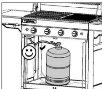
natural_image
Line drawing of a gas stove with a water dispenser and a smiley face indicator (no text or symbols)natural_image
Technical diagram of a mechanical assembly with cross-sectional views and a magnified inset showing internal components (no text or symbols)natural_image
3D mechanical component diagrams showing two views of a device with labeled parts (no text or symbols present)
Fettpanne
natural_image
Three different heat exchanger or venturi components shown in black, dark gray, and light gray, with no visible text or symbols.natural_image
3D diagram of a grid-patterned plate with an oval cutout and an arrow pointing to it (no text or symbols)natural_image
Two gray metal mesh plates with circular cutouts, one open and one closed (no text or symbols visible)natural_image
Two mechanical components with arrows indicating assembly or movement, no visible text or symbolsnatural_image
Two identical line drawings of a gas stove with a cylindrical tank, showing mechanical components and wiring (no text or symbols)natural_image
Technical diagram of a mechanical assembly with directional arrows and gear symbols (no text or labels)natural_image
Technical diagram of a mechanical assembly with exploded view and close-up views (no text or symbols)natural_image
3D mechanical component diagrams showing two views of a square base with internal components and arrows indicating assembly (no text or symbols)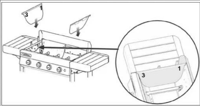
Fettbricka
natural_image
Three different plastic heat exchanger or venturi components shown from different angles (no text or symbols visible)natural_image
3D diagram of a grid-patterned plate with an oval cutout and an arrow pointing to it (no text or symbols)natural_image
Two mechanical components with arrows indicating motion, one showing a pipe fitting and the other a handle (no text or symbols visible)natural_image
Pure mechanical diagram showing a lever mechanism with arrows and gear symbols (no text or labels)natural_image
Diagram of a gas stove with a water dispenser and a smiley face indicator (no text or symbols)natural_image
Technical diagram of a mechanical device with internal components and exploded view, showing no text or symbolsSBĚRNÁ NÁDOBA NA TUK
natural_image
Three views of a black plastic heat exchanger or vent, showing internal structure and mounting points (no text or symbols)natural_image
3D rendering of a gray plastic tray with circular cutouts and a top lid (no text or symbols)- obvodovým dílem
natural_image
Pure mechanical diagram showing a lever mechanism with no text, numbers, or symbolsnatural_image
Illustration of a gas cylinder connected to a water dispenser with a smiley face indicator (no text or symbols)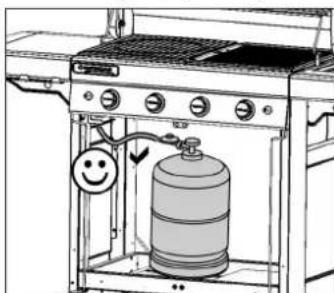
natural_image
Line drawing of a gas stove with a water dispenser and a smiley face indicator (no text or symbols)natural_image
Technical diagram of a mechanical device with exploded view and close-up views (no text or symbols)
Tacka na tłuszcz
natural_image
3D diagram of a grid-patterned panel with an oval cutout and an arrow pointing to it (no text or symbols)Drewno
natural_image
Two gray plastic or metal components with circular cutouts, one partially filled and the other empty (no text or symbols visible)natural_image
Pure mechanical diagram showing a lever and gear mechanism without any text, numbers, or symbols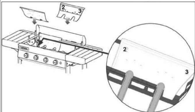

natural_image
Three different electronic components: a black rectangular fan with ribbed top, a black rectangular panel with a central dot, and a gray rectangular slatted cover (no text or symbols visible)natural_image
3D diagram of a grid-patterned plate with an oval cutout and an arrow pointing to it (no text or symbols)- Madera
natural_image
Two gray plastic mesh plates with circular cutouts and a top lid (no text or symbols visible)natural_image
Two mechanical components with arrows indicating motion, one showing a pipe fitting and the other a handle (no text or symbols visible)natural_image
Two identical diagrams of a gas cylinder being heated by an outdoor grill, with no text or symbols present.natural_image
Pure mechanical diagram showing a lever mechanism with arrows indicating motion, no text or symbols presentnatural_image
Two 3D mechanical components with arrows indicating assembly or movement, no visible text or symbolsI) SLUKNING AF KOGEPLADEN
(afhænger af model)

FEDTOPSAMLINGSBAKKE
natural_image
Three different heat exchanger or venturi components shown in black, dark gray, and light gray, with no visible text or symbols.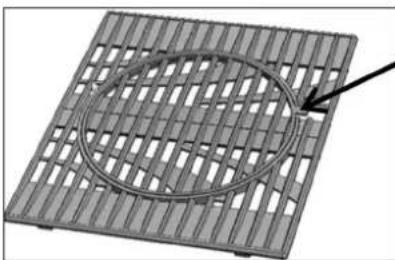
natural_image
3D diagram of a grid-patterned plate with an oval cutout and an arrow pointing to it (no text or symbols)TRAE
natural_image
Two gray metal plates with circular cutouts, one lid open and one square flat (no text or symbols visible)i
natural_image
Exterior view of a mechanical connector assembly (no text or symbols visible)natural_image
Two identical line drawings of a gas cylinder being heated by an outdoor stove, with no text or symbols present.natural_image
Diagram of a mechanical or electrical component with directional arrows and symbols, no readable text or labels present.natural_image
Diagram of a mechanical device with three views showing internal components and alignment, no text or symbols present.natural_image
3D mechanical component diagrams showing two views of a base with labeled parts (no text or symbols present)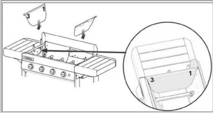
RASVANKERÄYSASTIA
natural_image
Three different electronic components: a black rectangular fan with slots, a black rectangular cover, and a gray rectangular vent with slats (no text or symbols visible)natural_image
3D rendering of a grid-patterned metal plate with an oval cutout and an arrow pointing to it (no text or symbols)PUU
natural_image
3D rendering of a square metal plate with circular cutouts and a circular top panel (no text or symbols)natural_image
Exterior view of a mechanical connector assembly (no text or symbols visible)natural_image
Pure mechanical diagram showing a lever mechanism with arrows indicating motion, no text or symbols presentnem


natural_image
Three different types of heat exchanger or venturi components shown in black and gray, with no visible text or symbols.natural_image
3D diagram of a grid-patterned panel with an oval cutout and an arrow pointing to it (no text or symbols)Fa
natural_image
Two gray plastic or metal components with circular cutouts, placed on a square base (no text or symbols visible)- keret
egyözponti elem.
natural_image
Mechanical assembly diagram showing a pipe fitting with a valve and a separate cylindrical component (no text or symbols)natural_image
Two identical line drawings of a gas stove with a cylinder inside, connected by tubing to a gas cylinder (no text or symbols present)natural_image
Technical diagram of a mechanical assembly with arrows indicating motion or force direction (no text or symbols)natural_image
Diagram of a gas stove with a water dispenser and a smiley face indicator (no text or symbols)natural_image
3D mechanical component diagrams showing two views of a device with labeled parts (no text or symbols present)natural_image
Three different plastic heat exchanger or venturi components shown from different angles (no text or symbols visible)natural_image
3D diagram of a grid-patterned plate with an oval cutout and an arrow pointing to it (no text or symbols)Les (glede na model)
natural_image
Two gray plastic slatted panels with circular cutouts, one open and one closed (no text or symbols visible)nite
obroba,
- središčna mreža.
Pesek
natural_image
Cross-sectional view of a mechanical connector with threaded ends and internal components (no text or symbols visible)natural_image
Diagram of a gas stove with a gas cylinder and pipe connection (no text or labels)natural_image
Pure mechanical diagram showing a lever mechanism with arrows and gear symbols (no text or labels)natural_image
Illustration of a gas cylinder connected to a water dispenser with a smiley face indicator (no text or symbols)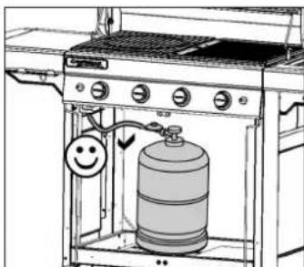
natural_image
Diagram of a gas stove with a water dispenser and a smiley face indicator (no text or symbols)

Podnos na zbieranie tuku
natural_image
Three different metal grate structures with mounting holes, shown from different angles (no text or symbols)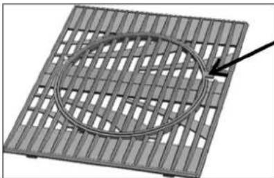
natural_image
3D diagram of a mesh grid with an elliptical cutout and an arrow pointing to it (no text or symbols)Drevo (podl'a modelu)
natural_image
Two gray metal mesh plates with circular cutouts, one lid partially filled with a perforated edge (no text or symbols visible)natural_image
Two identical line drawings of a gas stove with a water cylinder inside, connected by tubing to a gas cylinder (no text or symbols present)natural_image
Technical diagram of a mechanical assembly with directional arrows and components (no text or labels)ne
natural_image
Diagram of a gas stove with a water dispenser and a smiley face indicator (no text or symbols)- otvori za ventilaciju na posudi s plinom ne smiju biti blokirani.
- da je/su posuda/e za masnoću ispravno i dokle god je moguće umetnuta/e u pripadajući/e odjeljak/odjeljke te da je/su ispravno pozicionirana/e.
- da je šest (6) odstranjivih dijelova posude natrag na mjesto (vidi odlomak p) Čišćenje i održavanje)

Dobro provjerite da Venturi cijevi (VT) pokrivaju brizgalice (IJ)
h) PALJENJE PLAMENIKA ROŠTILJA
- Otvorite poklopac roštilja.
- Regulatori paljenja moraju biti u položaju (isključeno).
- Pritisnite i okrenite ručicu za podešavanje suprotnom od smjera kazaljke na satu i postavite je u poziciju punog dotoka (4)
natural_image
Technical diagram of a mechanical assembly with exploded view and close-up views (no text or symbols)"OFJF"ISKUJUČIVANJE ROŠTILJA
u Ventjerčice u položaj "OFF" (O), a zatim zatvorite izlazni ventil na plinskoj boci.
k) PALJENJE KUHALA (ovisno o modelu)

Posuda za skupljanje masnoće
ovisno o modelu, vaš roštilj opremljen je je dvjema posudama za skupljanje masnoće. Preporučuje se da istu/iste očistite nakon svake uporabe. posude se mogu prati u perilici posuđa.
Kako bi se olakšalo čišćenje, širina posuda za skupljanje masnoće dizajnirana je tako da se može prekriti komadom aluminijske folije, koja se može kupiti u trgovinama, prije nego se roštilj stavi u uporabu.
Bacite foliju nakon uporabe roštilja.
natural_image
Three different heat exchanger or venturi components shown in black and gray, with no visible text or symbols.natural_image
3D diagram of a grid-patterned plate with a circular cutout and an arrow pointing to it, labeled 'dijela' and 'g' (no other text or symbols)Drvo (ovisno o modelu)
Dijelovi roštilja od drveta su u svrhu održavanja prirodnog izgleda i njihove Campingaz® zaštitnom navlakom k možete pronaći u prodaji kao dio asortimana Campingaz® pribora.
natural_image
Two gray metal mesh plates with circular cutouts, one open and one closed (no text or symbols visible)natural_image
Technical line drawing of a portable gas cylinder mounted on a machine (no text or symbols)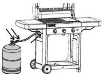
natural_image
Line drawing of a gas stove with a gas cylinder and attached barrel (no text or symbols)de la
natural_image
Pure mechanical diagram showing a lever mechanism with arrows and gear symbols (no text or labels)natural_image
Line drawing of a gas stove with a water dispenser and a smiley face indicator (no text or symbols)

Tava de colectare a grăsimii
natural_image
Three different metal grate structures with mounting holes, shown from different angles (no text or symbols)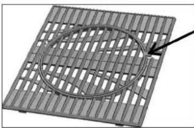
natural_image
3D diagram of a grid-patterned plate with an elliptical hole and an arrow pointing to it (no text or symbols)natural_image
Diagram of a circular component with a flat top and rectangular base, labeled 'din' (no text or symbols on the diagram itself)natural_image
Two mechanical components with arrows indicating motion, one showing a knob and the other a handle (no text or symbols visible)natural_image
Pure mechanical diagram showing a lever mechanism with arrows and gear symbols (no text or labels)natural_image
Technical diagram of a mechanical device with exploded view and close-up views (no text or symbols)
natural_image
3D rendering of a grid-patterned metal grate with an oval cutout and an arrow pointing to it (no text or symbols)Дървени елементи
natural_image
3D rendering of a square metal plate with circular cutouts and a circular top panel (no text or symbols)natural_image
Pure mechanical diagram showing a lever mechanism with arrows indicating motion, no text or symbols presentnatural_image
Illustration of a gas cylinder connected to a water dispenser with a smiley face indicator (no text or symbols)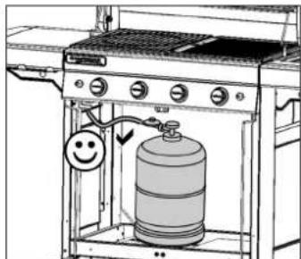
natural_image
Line drawing of a gas stove with a water dispenser and a smiley face indicator (no text or symbols)natural_image
Technical diagram of a mechanical assembly with two views showing internal components (no text or symbols)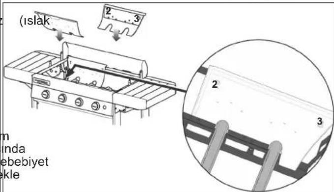
Yağ toplama tepsisi
natural_image
Three different metal grate structures with ventilation grilles, shown from different angles (no text or symbols visible)natural_image
3D mesh grid with a circular cutout and an arrow pointing to it (no text or symbols)Ahşap
natural_image
Two gray plastic or metal components with circular cutouts, no visible text or symbolsnatural_image
Diagram of a gas stove with a gas cylinder and attached barrel, showing no text or symbolsnatural_image
Pure mechanical diagram showing a lever mechanism with arrows indicating motion, no text or symbols present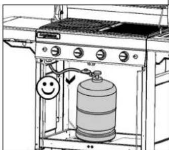
natural_image
Technical diagram of a mechanical device with internal components and exploded view, showing no text or symbolsnatural_image
3D mechanical component diagrams showing a component being inserted into a housing, with arrows indicating direction (no text or symbols present)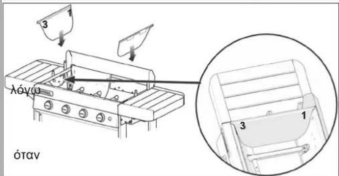
natural_image
Three different heat exchanger or venturi components shown in black, dark gray, and light gray, with no visible text or symbols.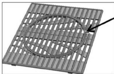
natural_image
3D diagram of a mesh grid with an elliptical cutout and an arrow pointing to it (no text or symbols)natural_image
Two gray plastic or metal components with circular cutouts, one open and one closed (no text or symbols visible)
- FR
- Bois :
- Operation and maintenance
- a) FOR YOUR SAFETY
- b) LOCATION
- c) GAS CYLINDER
- France (depending on model)
- Switzerland, Germany, Austria:
- e) LID
- f) CHECKING FOR GAS LEAKS
- Important:
- PRIOR TO USE
- If your barbecue grill is equipped with a piezoelectric igniter:
- If your barbecue grill is equipped with an electronic spark igniter:
- Lighting:
- - If your barbecue grill is equipped with a piezoelectric igniter:
- - If your barbecue grill is equipped with an electronic spark igniter:
- M) Lighting of the console
- n) REPLACING THE GAS CYLINDER
- o) OPERATION
- Control panel
- Firebox wall
- GB
- Grease collection tray
- Cooking plate and grill
- Wood (depending on the model)
- q) STORAGE
- in r) ACCESSORIES the bottom of
- s) PROTECTING THE ENVIRONMENT
- t) BATTERY RECOMMENDATIONS
- u) ELECTRICAL AND ELECTRONIC WASTE
- USO E MANUTENZIONE
- h) ACCENSIONE DEL BRUCIATORE DEL BARBECUE
- - Vetopvangbak
- DE
- FETTAUFFANGBLECH
- Fettpanne
- Fettbricka
- SBĚRNÁ NÁDOBA NA TUK
- Tacka na tłuszcz
- Drewno
- - Madera
- I) SLUKNING AF KOGEPLADEN
- FEDTOPSAMLINGSBAKKE
- TRAE
- RASVANKERÄYSASTIA
- PUU
- Fa
- Les (glede na model)
- Podnos na zbieranie tuku
- Drevo (podl'a modelu)
- h) PALJENJE PLAMENIKA ROŠTILJA
- "OFJF"ISKUJUČIVANJE ROŠTILJA
- k) PALJENJE KUHALA (ovisno o modelu)
- Posuda za skupljanje masnoće
- Drvo (ovisno o modelu)
- Tava de colectare a grăsimii
- Дървени елементи
- Yağ toplama tepsisi
- Ahşap
Brand : CAMPINGAZ
Model : 4 Series Classic LS Plus
Category : Barbecue