GDS 14 4 VLI Professional - Drill BOSCH - Free user manual and instructions
Find the device manual for free GDS 14 4 VLI Professional BOSCH in PDF.
Download the instructions for your Drill in PDF format for free! Find your manual GDS 14 4 VLI Professional - BOSCH and take your electronic device back in hand. On this page are published all the documents necessary for the use of your device. GDS 14 4 VLI Professional by BOSCH.
USER MANUAL GDS 14 4 VLI Professional BOSCH
OBJ_BUCH-832-007.book Page 2 Tuesday, September 6, 2016 9:58 AM3 | 1 609 92A 2CV | (6.9.16) Bosch Power Tools OBJ_BUCH-832-007.book Page 3 Tuesday, September 6, 2016 9:58 AM1 609 92A 2CV | (6.9.16) Bosch Power Tools 4 |
GDR 18 V-LI Professional OBJ_BUCH-832-007.book Page 4 Tuesday, September 6, 2016 9:58 AM5 | 1 609 92A 2CV | (6.9.16) Bosch Power Tools
0 –3200 0 –3200 Maximum torque, hard screwdriving application according to ISO 5393 Nm 150* 160* Bolt size mm M6 –M14 M6 – M14 Tool holder ¼" hexagon socket ¼" hexagon socket Weight according to EPTA-Procedure 01:2014 kg 1.4 – 1.7* 1.5 – 1.9* Permitted ambient temperature – during charging – during operation
0–3200 0 –3200 Maximum torque, hard screwdriving application according to ISO 5393 Nm 170* 180* Bolt size mm M6 – M16 M6 – M16 Tool holder
Weight according to EPTA-Procedure 01:2014 kg 1.4 – 1.7* 1.5 – 1.9* Permitted ambient temperature – during charging – during operation
0 –3200 0 –3200 *depending on the battery pack being used ** Limited performance at temperatures <0 °C OBJ_BUCH-832-007.book Page 15 Thursday, September 8, 2016 9:07 AM16 | English 1 609 92A 2CV | (8.9.16) Bosch Power Tools Noise/Vibration Information Sound emission values determined according to EN 60745-2-2. Typically the A-weighted noise levels of the product are: Sound pressure level 96 dB(A); Sound power level 107 dB(A). Uncertainty K =3 dB. Wear hearing protection! Vibration total values a
(triax vector sum) and uncertainty K determined according to EN 60745: Impact tightening of fasteners of the maximum capacity of the tool: a
The vibration level given in this information sheet has been measured in accordance with a standardised test given in EN 60745 and may be used to compare one tool with anoth- er. It may be used for a preliminary assessment of exposure. The declared vibration emission level represents the main ap- plications of the tool. However if the tool is used for different applications, with different accessories or insertion tools or is poorly maintained, the vibration emission may differ. This may significantly increase the exposure level over the total working period. An estimation of the level of exposure to vibration should also take into account the times when the tool is switched off or when it is running but not actually doing the job. This may sig- nificantly reduce the exposure level over the total working period. Identify additional safety measures to protect the operator from the effects of vibration such as: maintain the tool and the accessories, keep the hands warm, organisation of work pat- terns. Declaration of Conformity We declare under our sole responsibility that the product de- scribed under “Technical Data” is in conformity with all rele- vant provisions of the directives 2009/125/EC (Regulation 1194/2012), 2011/65/EU, 2014/30/EU, 2006/42/EC including their amendments and complies with the following standards: EN 60745-1, EN 60745-2-2, EN 50581. Technical file (2006/42/EC) at: Robert Bosch Power Tools GmbH, PT/ECS, 70538 Stuttgart, GERMANY Robert Bosch Power Tools GmbH 70538 Stuttgart, GERMANY Stuttgart, 01.01.2017 Assembly Battery Charging Use only the battery chargers listed on the accessories page. Only these battery chargers are matched to the lith- ium-ion battery of your power tool. Note: The battery supplied is partially charged. To ensure full capacity of the battery, completely charge the battery in the battery charger before using your power tool for the first time. The lithium-ion battery can be charged at any time without re- ducing its service life. Interrupting the charging procedure does not damage the battery. Maximum torque, hard screwdriving application according to ISO 5393 –¼" hexagon socket
Weight according to EPTA-Procedure 01:2014 kg 1.5 – 1.7* 1.5 – 2.0* Permitted ambient temperature – during charging – during operation
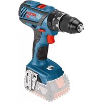
0...+45 -20...+50 0...+45 -20...+50 Recommended batteries GBA 14,4V.. GBA 18V.. Recommended chargers AL18.. GAL 3680 AL18.. GAL 3680 Cordless Impact Screwdriver GDX 14,4 V-LI GDX 18 V-LI *depending on the battery pack being used ** Limited performance at temperatures <0 °C Henk Becker Executive Vice President Engineering and Manufacturing Helmut Heinzelmann Head of Product Certification PT/ECS OBJ_BUCH-832-007.book Page 16 Thursday, September 8, 2016 9:07 AMEnglish | 17 Bosch Power Tools 1 609 92A 2CV | (8.9.16) The lithium-ion battery is protected against deep discharging by the “Electronic Cell Protection (ECP)”. When the battery is empty, the machine is switched off by means of a protective circuit: The inserted tool no longer rotates. Do not continue to press the On/Off switch after the machine has been automatically switched off. The bat- tery can be damaged. Observe the notes for disposal. Removing the battery The battery 5 is equipped with two locking levels that should prevent the battery from falling out when pushing the battery unlocking button 6 unintentionally. As long as the battery is inserted in the power tool, it is held in position by means of a spring. To remove the battery 5, press the unlocking button 6 and pull out the battery toward the front. Do not exert any force. Changing the Tool (see figure A–C) Before any work on the machine itself (e. g. mainte- nance, tool change, etc.) as well as during transport and storage, remove the battery from the power tool. There is danger of injury when unintentionally actuating the On/Off switch. Regularly clean the power tool’s air vents. The motor’s fan will draw the dust inside the housing and excessive ac- cumulation of powdered metal may cause electrical haz- ards. GDR 14,4 V-LI/GDR 18 V-LI/GDX 14,4 V-LI/GDX 18 V-LI: Inserting Pull the locking sleeve 2 forward, push the insert tool to the stop into the tool holder 1 and release the locking sleeve 2 to lock the insert tool. Use only screwdriver bits with ball catch
Other screwdriver bits 13 can be used with a universal bit holder with ball catch 12. Removing Pull the locking sleeve 2 forward and remove the insert tool. GDS14,4V-LI/GDS18V-LI/GDX14,4V-LI/GDX18V-LI: When working with an application tool, pay attention that the application tool is connected securely on the tool holder. When the application tool is not securely con- nected with the tool holder, it can come off during applica- tion. Slide the application tool 14 onto the square drive of the tool holder 1. With this system, there will be a slight amount of play around the application tool 14 after connecting securely to the tool holder 1; this has no influence on the function/safety. Operation Method of Operation The tool holder 1 with the tool is driven by an electric motor via a gear and impact mechanism. The working procedure is divided into two phases: Screwing in and tightening (impact mechanism in action). The impact mechanism is activated as soon as the screwed connection runs tight and thus load is put on the motor. In this instance, the impact mechanism converts the power of the motor to steady rotary impacts. When loosening screws or nuts, the process is reversed. Starting Operation Inserting the battery Set the rotational direction switch 7 to the centre position to protect the power tool against accidental starting. Insert the charged battery 5 from the front into the base of the power tool until the battery is securely locked. Reversing the rotational direction (see figure D) The rotational direction switch 7 is used to reverse the rota- tional direction of the machine. However, this is not possible with the On/Off switch 8 actuated. Right Rotation: For driving in screws and tightening nuts, press the rotational direction switch 7 through to the left stop. Left Rotation: For loosening and unscrewing screws and nuts, press the rotational direction switch 7 through to the right stop. Switching On and Off To start the machine, press the On/Off switch 8 and keep it pressed. The power light 9 lights up when the On/Off switch 8 is slightly or completely pressed, and allows the work area to be illumi- nated when lighting conditions are insufficient. To switch off the machine, release the On/Off switch 8. To save energy, only switch the power tool on when using it. Adjusting the Speed The speed of the switched-on power tool can be variably ad- justed, depending on how far the On/Off switch 8 is pressed. Light pressure on the On/Off switch 8 results in a low rotation- al speed. Further pressure on the switch results in an increase in speed. Working Advice Apply the power tool to the screw/nut only when it is switched off. Rotating tool inserts can slip off. The torque depends on the impact duration. The maximum achieved torque results from the sum of all individual torques achieved through impact. The maximum torque is achieved OBJ_BUCH-832-007.book Page 17 Thursday, September 8, 2016 9:07 AM18 | English 1 609 92A 2CV | (8.9.16) Bosch Power Tools after an impact duration of 6–10 seconds. After this dura- tion, the tightening torque is increased only minimally. The impact duration is to be determined for each required tightening torque. The actually achieved tightening torque is always to be checked with a torque wrench. Screw Applications with Hard, Spring-loaded or Soft Seat A test in which the achieved torques in an impact series are measured and transferred to a diagram will produce the curve of a torque characteristic. The height of the curve corre- sponds with the maximum reachable torque, and the steep- ness indicates the duration in which this is achieved. A torque gradient depends on the following factors: – Strength properties of the screws/nuts – Type of backing (washer, disc spring, seal) – Strength properties of the material being screwed/bolted together – Lubrication conditions at the screw/bolt connection The following application cases result accordingly: –A hard seat is given for metal-to-metal screw applications with the use of washers. After a relatively short impact du- ration, the maximum torque is reached (steep characteris- tic curve). Unnecessary long impact duration only causes damage to the machine. –A spring-loaded seat is given for metal-to-metal screw ap- plications, however with the use of spring washers, disc springs, studs or screws/nuts with conical seat as well as when using extensions. –A soft seat is given for screw applications, e. g., metal on wood or when using lead washers or fibre washers as back- ing. For a spring-loaded seat as well as for a soft seat, the maxi- mum tightening torque is lower than for a hard seat. Also, a clearly longer impact duration is required. Reference Values for Maximum Screw/Bolt Tightening Torques Calculated from the tensional cross-section; utilization of the yield point 90 % (with friction coefficient μ total = 0.12). As a control measure, always check the tightening torque with a torque wrench. Tips Before screwing larger, longer screws into hard materials, it is advisable to predrill a pilot hole with the core diameter of the thread to approx.
of the screw length. Note: Pay attention that no metal particles enter the power tool. Belt Clip With the belt clip 4, the machine can be hung onto a belt. The user has both hands free and the machine is always at hand. Recommendations for Optimal Handling of the Battery Protect the battery against moisture and water. Store the battery only within a temperature range between –20 °C and 50 °C. As an example, do not leave the battery in the car in summer. Occasionally clean the venting slots of the battery using a soft, clean and dry brush. A significantly reduced working period after charging indi- cates that the battery is used and must be replaced. Observe the notes for disposal. Maintenance and Service Maintenance and Cleaning Before any work on the machine itself (e. g. mainte- nance, tool change, etc.) as well as during transport and storage, remove the battery from the power tool. There is danger of injury when unintentionally actuating the On/Off switch. For safe and proper working, always keep the machine and ventilation slots clean. Replacing the Carbon Brushes (see figure E) Check the length of the carbon brushes approx. every 2–3 months and replace the carbon brushes if required. Never replace only a single carbon brush! Note: Use only carbon brushes supplied by Bosch and intend- ed specifically for your product. – Unscrew the caps 16 using a suitable screwdriver. – Replace the spring-loaded carbon brushes 15 and screw the caps back on again. Property Classes according to DIN 267 Standard Screws/Bolts High-strength Bolts
GBA 14,4V.. GBA 18V.. OBJ_BUCH-832-007.book Page 224 Tuesday, September 6, 2016 10:18 AM