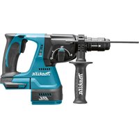
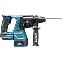
HR3820 - Drill MAKITA - Free user manual and instructions
Find the device manual for free HR3820 MAKITA in PDF.

Frequently Asked Questions - HR3820 MAKITA
User questions about HR3820 MAKITA
0 question about this device. Answer the ones you know or ask your own.
Ask a new question about this device
Download the instructions for your Drill in PDF format for free! Find your manual HR3820 - MAKITA and take your electronic device back in hand. On this page are published all the documents necessary for the use of your device. HR3820 by MAKITA.
USER MANUAL HR3820 MAKITA
GB Rotary Hammer Instruction Manual
F Perforateur Manuel d'instructions
D Bohrhammer Betriebsanleitung
1 Martello rotativo Istruzioni per l'uso
NL Boor-en breekhamer Gebruiksaanwijzing
E Martillo rotativo Manual de instructaciones
P Martelo misto Manual de instruções
DK Borehammer Brugsanvisning
s Borrhammare Bruksanvisning
N Borhammer Bruksanvisning
SF Poravasara Kayttoohje
GR Περιστροφικό σφυρί Oδηγες χρήσεως
35 mm HR3520
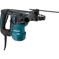
38 mm HR3850

1
2
3
4
5
6
7
8
9
10
11 12
13 14
Symbols
The following show the symbols used for the tool. Be sure that you understand their meaning before use.
Symboles
Explanation of general view
1 Side grip
2 Grip base
3 Tool retainer
4 Change lever
5 For rotation with hammering
6 For hammering only
7 Wing bolt
8 Depth gauge
9 Switch trigger
10 Core bit
11 Adapter
12 Center bit
13 Rod
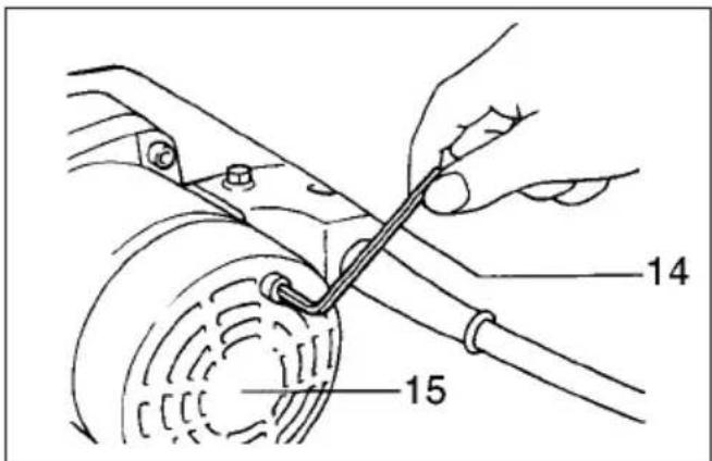
14 Hex wrench
15 Rear cover
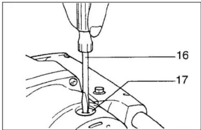
16 Screwdriver
17 Brush holder cap
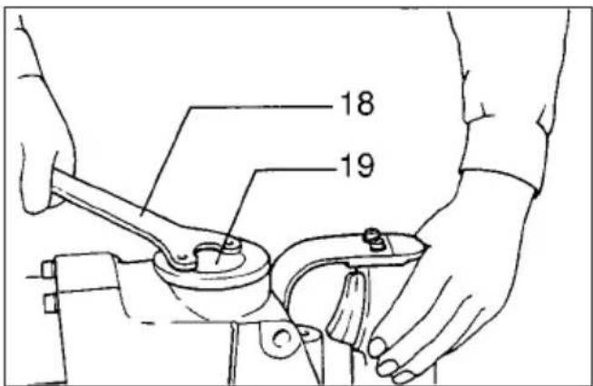
18 Lock nut wrench
19 Crank cap
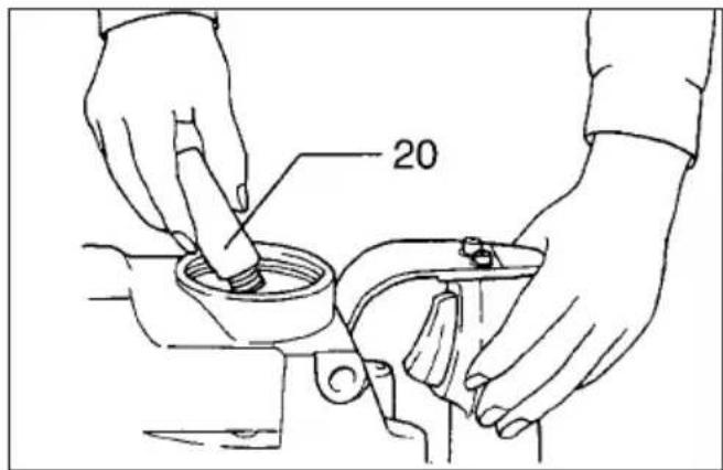
20 Hammer grease
SPECIFICATIONS
Model HR3520 HR3850
Capacities
Tungsten-carbide bit 35 mm 38 mm
Core bit 79 mm 118 mm
No load speed (mi) 440 240
Blows per min. 3,300
Overall length 386 mm 430 mm
Net weight 6.4 kg 7.5 kg
- Due to our continuing program of research and development, the specifications herein are subject to change without notice.
- Note: Specifications may differ from country to country.
Power supply
The tool should be connected only to a power supply of the same voltage as indicated on the nameplate, and can be operated on single-phase AC/DC supply.
They are double-insulated in accordance with European Standard and can, therefore, also be used from sockets without earth wire.
Safety hints
For your own safety, please refer to the enclosed Safety instructions.
ADDITIONAL SAFETY RULES
- Wear a hard hat (safety helmet), safety glasses and/or face shield. It is also highly recommended that you wear a dust mask, ear p tectors and thickly padded gloves.
- Be sure the bit is secured in place before operation.
- Under normal operation, the tool is designed to produce vibration. The screws can come loose easily, causing a breakdown or accident. Check tightness of screws carefully before operation.
-
In cold weather or when the tool has not been used for a long time, let the tool warm up to several minutes by operating it under no load. This will loosen up the lubrication. Without proper warm-up, hammering operation is difficult.
-
Always be sure you have a firm footing. Be sure no one is below when using the tool in high locations.
- Hold the tool firmly with both hands.
- Keep hands away from moving parts.
-
Do not leave the tool running. Operate the tool only when hand-held.
-
Do not point the tool at any one in the area when operating. The bit could fly out and injure someone seriously.
-
When drilling or chipping into walls, floors or wherever "live" electrical wires may be encountered, DO NOT TOUCH ANY METAL PARTS OF THE TOOL!
Hold the tool by the insulated grasping surfaces to prevent electric shock if you drill or chip into a "live" wire. - Do not touch the bit or parts close to the bit immediately after operation; they may be extremely hot and could burn your skin.
SAVE THESE INSTRUCTIONS.
OPERATING INSTRUCTIONS
Side grip (auxiliary handle) (Fig. 1 & 2)
For maximum control and safer operation, always use the side grip with this tool. The side grip swings around to either side, allowing easy handling of the tool in any position. Loosen the side grip by turning it counterclockwise, swing it to the desired position and then tighten it by turning clockwise. (Fig. 1)
The side grip can also be installed in the position shown in Fig. 2. Remove the side grip from the grip base by turning the side grip counterclockwise. Screw the side grip on either side of the tool, whichever is convenient.
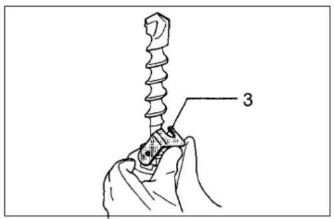
Installing or removing drill bit or other bits (bull point, etc.) (Fig. 3)
Important:
Always be sure that the tool is switched off and unplugged before installing or removing the bit.
Pivot the tool retainer to the side. (If it is difficult to move the tool retainer with your thumbs, tap it withC hammer.) Insert the bit into the tool barrel as far as will go. Return the tool retainer to its original position to secure the bit.
To remove the bit, follow the installation procedure reverse.
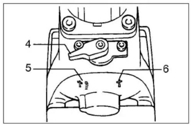
Selecting action mode (Fig. 4) (Not available for HR3520)
Rotation with hammering:
For drilling in concrete, masonry, etc., rotate the change lever to the position.
Hammering only:
For chipping, scaling or demolition operations, rotate the change lever to the position.
CAUTION:
- Do not rotate the change lever when the tool is running under load. The tool will be damaged.
- To avoid rapid wear on the mode change mechanism, be sure that the change lever is always positively located in one of the two action mode positions.
Adjusting depth of drilling (Fig. 5)
Loosen the wing bolt and adjust the depth gauge the desired depth. After adjusting, tighten the wing bolt.
Switch action (Fig. 6)
CAUTION:
- Before plugging in the tool, always check to see if the switch trigger actuates properly and returns to the "OFF" position when released.
- Do not tape, tie or otherwise secure the trigger in the "ON" position.
To start the tool, simply pull the trigger. Release the trigger to stop.
Hammer drilling operation
Position the bit at the location for the hole, then the trigger.
Do not force the tool. Light pressure gives best results. Keep the tool in position and prevent it from slipping away from the hole.
Do not apply more pressure when the hole becomes clogged with chips or particles. Instead, run the tool at an idle, then remove from the hole. By repeating this several times, the hole will be cleaned out.
CAUTION:
When the bit begins to break through concrete or if the bit strikes reinforcing rods embedded in concrete, the tool may react dangerously. Maintain good balance and safe footing while holding the tool firmly with both hands to prevent dangerous reaction.
Chipping / Scaling / Demolition
I hold the tool firmly with both hands. Turn the tool on and apply slight pressure on the tool so that the tool will not bounce around, uncontrolled. Pressing very hard on the tool will not increase the efficiency.
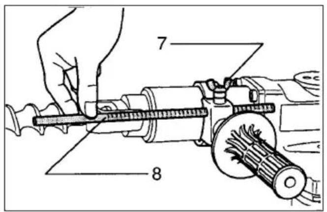
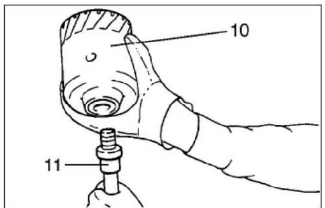
Core bit (optional accessory)
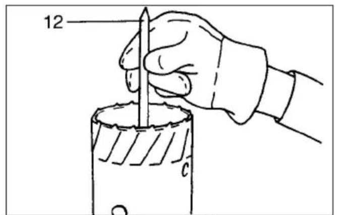
When using the center bit
Screw the core bit on the adapter. Install the adapter with the core bit in the tool in the same manner as a drill bit. (Fig. 7)
Install the center bit. (Fig. 8)
- Rest the core bit on the concrete and turn the tool on.
- Once the core bit has cut a shallow groove into the concrete, remove the center bit. Then resume drilling.
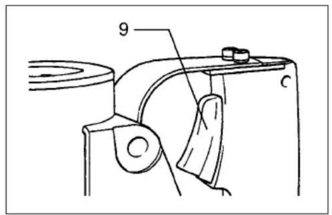
To remove the core bit, follow the procedures (1) or (2).
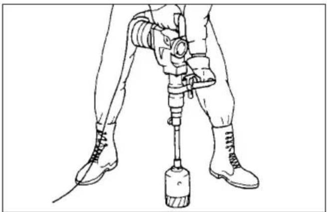
(1) Rotate the change lever to the position. Then rest the core bit on the concrete and turn the tool on. The core bit will come loose from the hammering action. (Fig. 9)
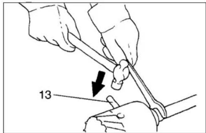
(2) Hold the adapter with the wrench, insert the rod (optional accessory) into the hole in the core bit to and tap with a hammer to unscrew. (Fig. 10)
When not using the center bit
Screw the core bit on the adapter. Install the adapter with the core bit in the tool in the same manner as a drill bit. (Fig. 7)
Rotate the change lever to the position. Rest the core bit on the concrete and turn the tool on. Once the core bit has cut a shallow groove into the concrete, rotate the change lever to the position and resume drilling.
NOTE:
No problem is caused even if the core bit unscrews slightly during brief use since the core bit rotates in the tightening direction.
To remove the core bit, follow the same removal procedures covered in When using the center bit.
MAINTENANCE
CAUTION:
Always be sure that the tool is switched off and unplugged before carrying out any work on the tool.
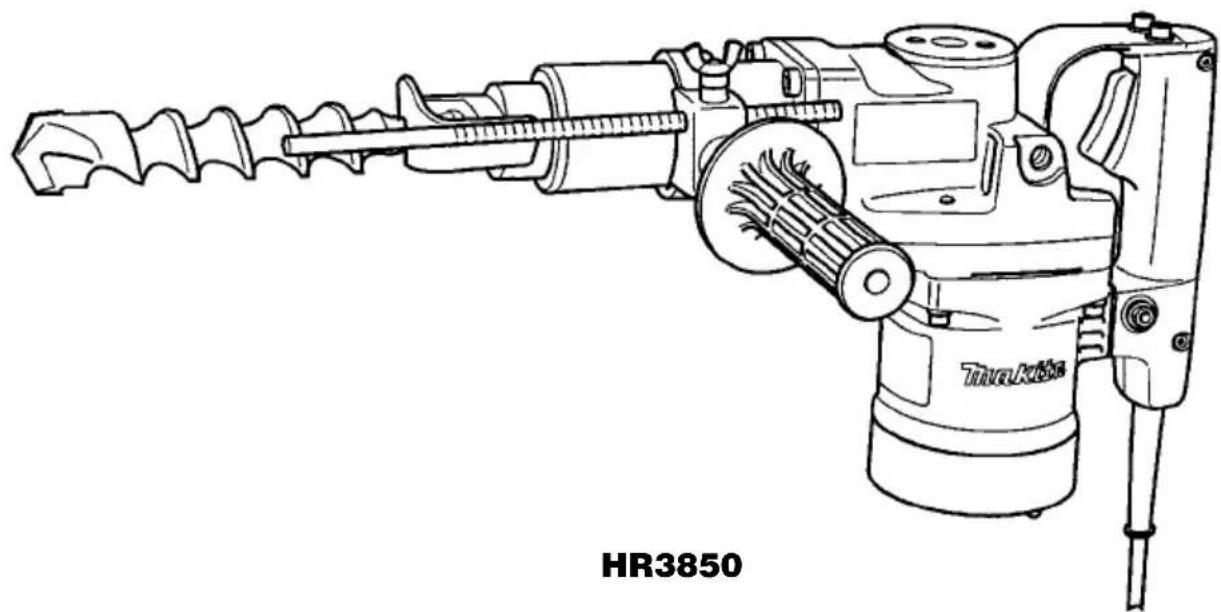
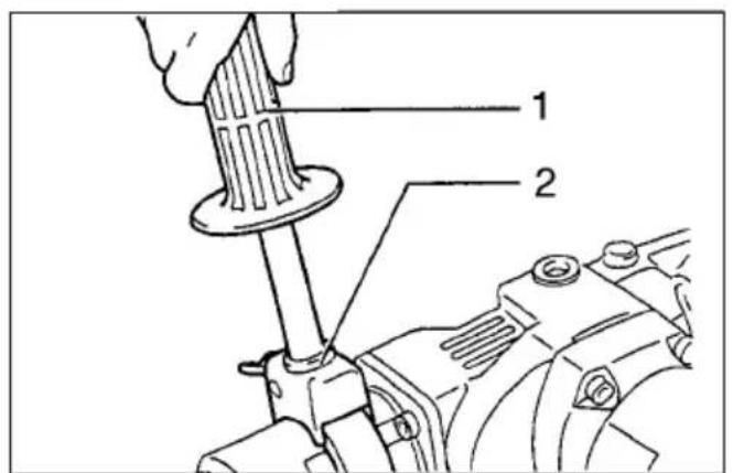
Replacement of carbon brushes (Fig. 11 & 12)
Whenever carbon brushes must be replaced, they cut out the tool automatically. When this occurs, replace both carbon brushes at the same time. Use only identical carbon brushes.
Lubrication (Fig. 13 & 14)
This tool requires no hourly or daily lubrication because it has a grease-packed lubrication system. Lubricate the tool every time the carbon brushes are replaced.
Run the tool for several minutes to warm it up. Switch off and unplug the tool. Remove the crank cap using a Makita lock nut wrench 35 (optional accessory). Rest the tool on the table with the bit end pointing upwards. This will allow the old grease to collect inside the crank housing. Wipe out the old grease inside and replace with a fresh grease (60g) .Use only Makita genuine grease (optional accessory). Filling with more than the specified amount of grease approx. 60~g can cause faulty hammering action or tool failure. Fill only with the specified amount of grease. Reinstall the crank cap and tighten with the lock nut wrench. Do not tighten the crank cap excessively. It is made of resin and is subject to breakage. To maintain product safety and reliability, repairs, maintenance or adjustment should be carried out by a Makita Authorized Service Center.
FRANÇAIS
Descriptif
Rotation et percussion
Burinage / Ecaillage / Demolition
EC-DECLARATION OF CONFORMITY
The undersigned, Yasuhiko Kanzaki, authorized by Makita Corporation, 3-11-8 Sumiyoshi-Cho, Anjo, Aichi 446-8502 Japan declares that this product
(Serial No.: series production)
manufactured by Makita Corporation in Japan is in compliance with the following standards or standardized documents,
HD400, EN50144, EN55014, EN61000
in accordance with Council Directives, 73/23/EEC, 89/336/EEC and 98/37/EC.
ITALIANO
HD400, EN50144, EN55014, EN61000.
ESPANOL
Director Aministratore
Director Directeur
Direktor Director
MAKITA INTERNATIONAL EUROPE LTD.
Michigan Drive, Tongwell, Milton Keynes,
Bucks MK15 8JD, ENGLAND
PORTUGUES
de acordo com as directivas 73/23/CEE, 89/336/CEE
EU-DEKLARATION OM KONFORMITET
Undertegnede, Yasuhiko Kanzaki, med fuldmagt fra Makita Corporation, 3-11-8 Sumiyoshi-Cho, Anjo, Aichi 446-8502 Japan, erklær hermed, at dette produit
Michigan Drive, Tongwell, Milton Keynes,
Bucks MK15 8JD, ENGLAND
ENGLISH
Noise and Vibration of Model HR3520
The typical A-weighted noise levels are
sound pressure level: 94 dB (A)
sound power level: 107 dB (A)
- Wear ear protection. -
The typical weighted root mean square acceleration O valor medio da acceleracao é 7 m/s value is 7 m²/s
FRANÇAISE
Noise and Vibration of Model HR3850
The typical A-weighted noise levels are
sound pressure level: 94 dB (A)
sound power level: 107 dB (A)
- Wear ear protection. -
The typical weighted root mean square acceleration O valor medio da acceleracao é 12 m/s value is 12 m²s