HR3001C - Drill MAKITA - Free user manual and instructions
Find the device manual for free HR3001C MAKITA in PDF.

User questions about HR3001C MAKITA
0 question about this device. Answer the ones you know or ask your own.
Ask a new question about this device
Download the instructions for your Drill in PDF format for free! Find your manual HR3001C - MAKITA and take your electronic device back in hand. On this page are published all the documents necessary for the use of your device. HR3001C by MAKITA.
USER MANUAL HR3001C MAKITA
natural_image
Technical line drawings of two different types of cylindrical mechanical components (no text or symbols present)

natural_image
Technical line drawing of a mechanical device with labeled component (no text or symbols beyond label)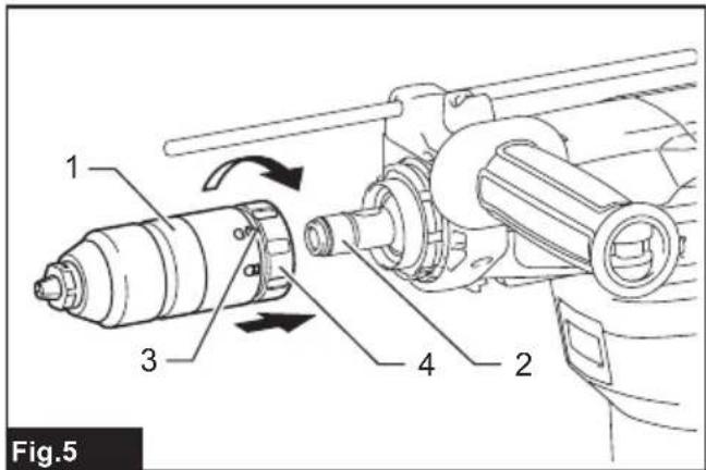
text_image
1 3 4 2 Fig.5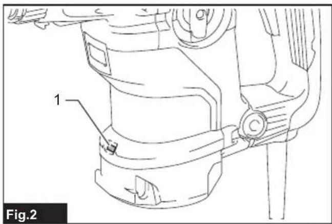
text_image
1 Fig.2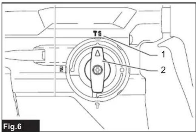
text_image
T5 1 2 Fig.6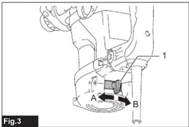
text_image
Fig.3 A B 1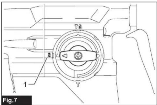
text_image
1 Fig.7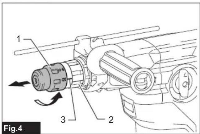
text_image
1 2 3 Fig.4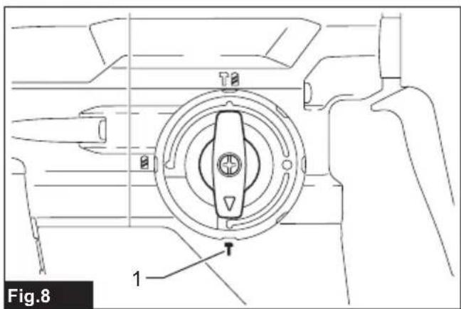
text_image
Fig.8 1
text_image
1 Fig.9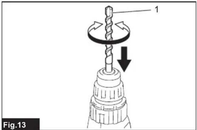
text_image
Fig.13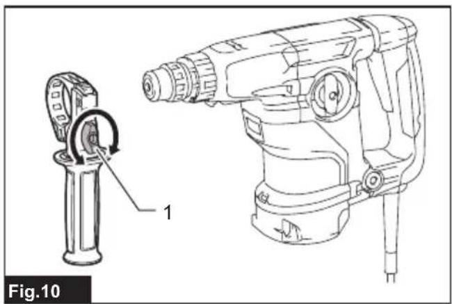
text_image
Fig.10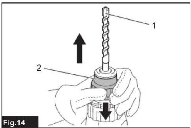
text_image
1 2 Fig.14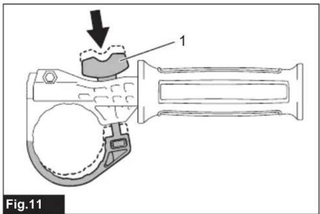
text_image
Fig.11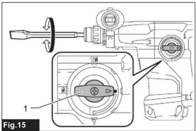
text_image
Fig.15 1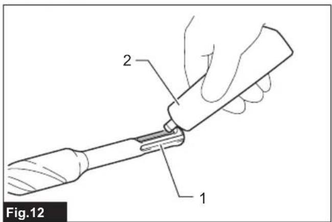
text_image
Fig.12 1 2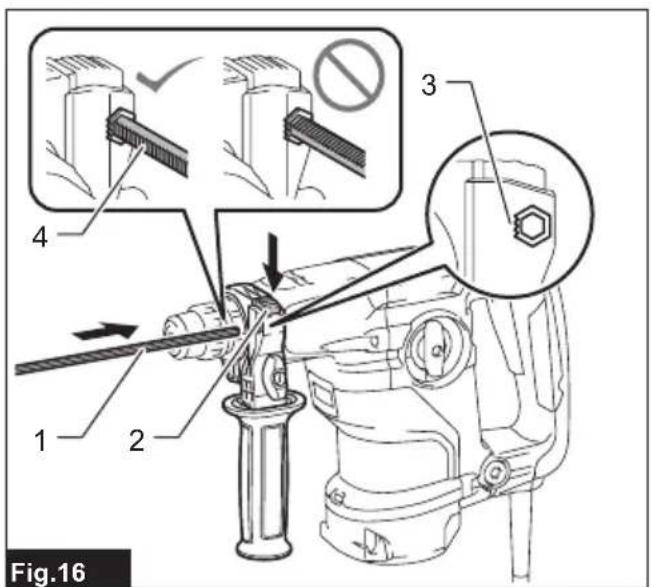
text_image
Fig.16 1 2 3 4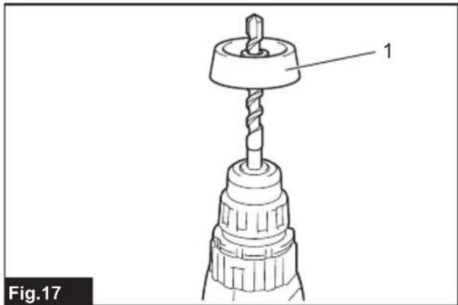
natural_image
Technical line drawing of a drill bit with a drill bit head and spiral drill bit (no text or symbols)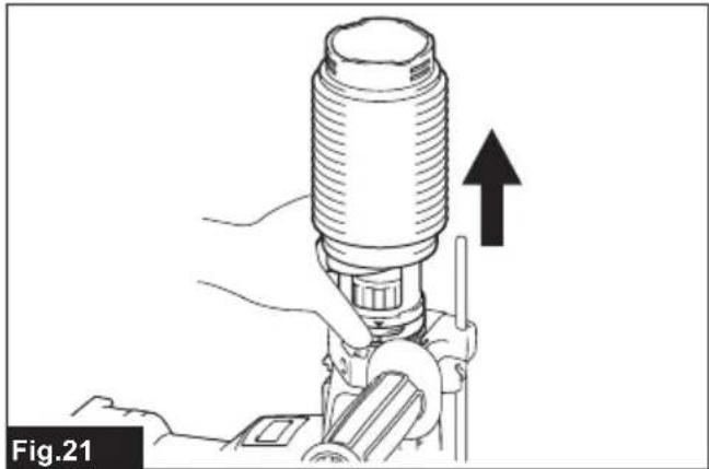
natural_image
Illustration of a hand operating a mechanical device with an upward arrow indicating motion (no text or symbols)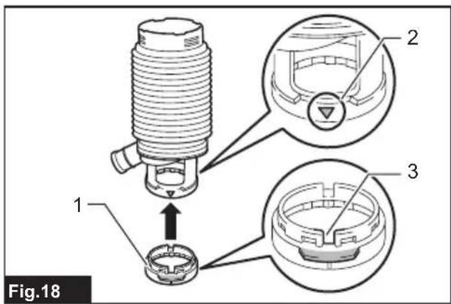
text_image
Fig.18 1 2 3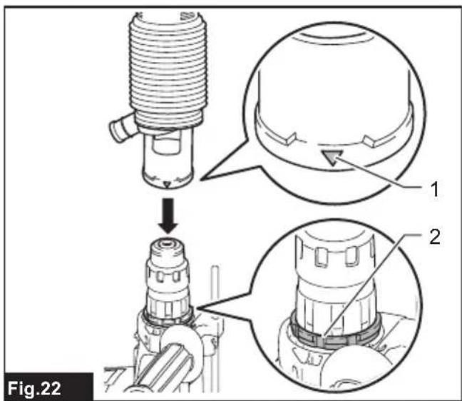
text_image
Fig.22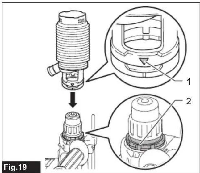
text_image
Fig.19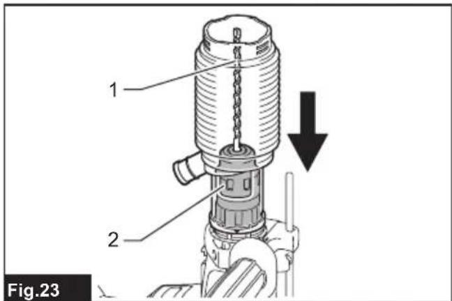
text_image
1 2 Fig.23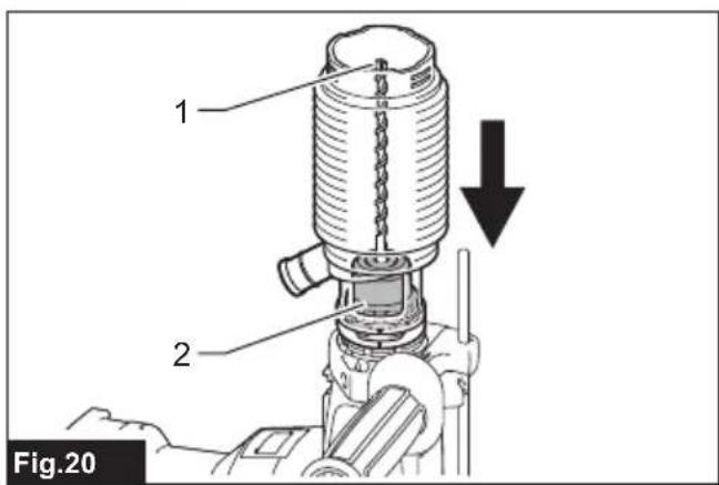
text_image
1 2 Fig.20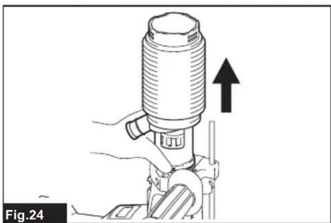
natural_image
Illustration of a hand operating a cylindrical device with an upward arrow, labeled Fig.24 (no text or symbols on the device itself)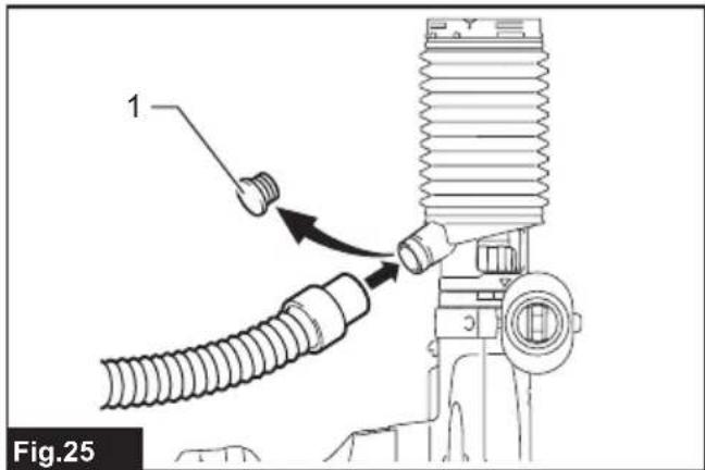
text_image
1 Fig.25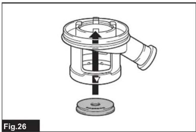
natural_image
Technical line drawing of a mechanical component with a central arrow indicating direction, no text or symbols present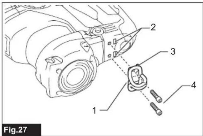
text_image
Fig.27 1 2 3 4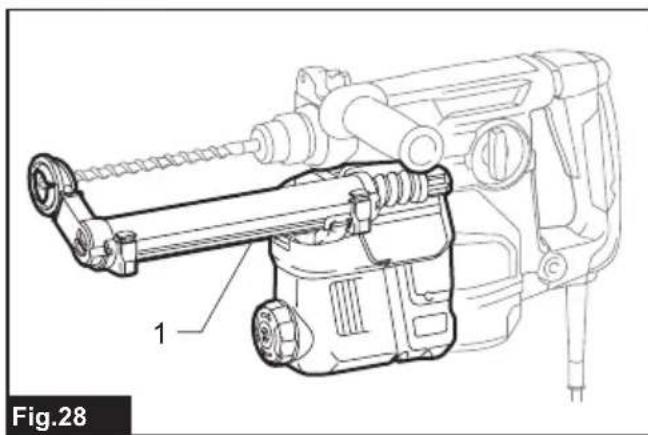
natural_image
Technical line drawing of a mechanical device with labeled component 1 (no text or symbols beyond label)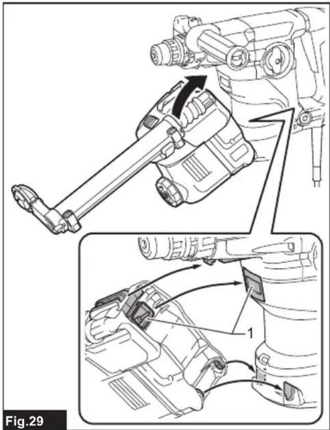
text_image
Fig.29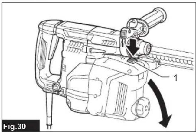
natural_image
Technical line drawing of a mechanical device with labeled component '1' and directional arrow (no text or symbols beyond label)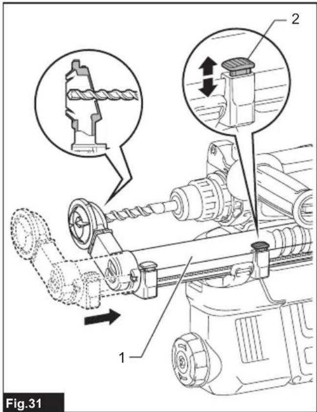
text_image
Fig.31 1 2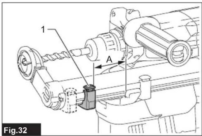
text_image
1 A Fig.32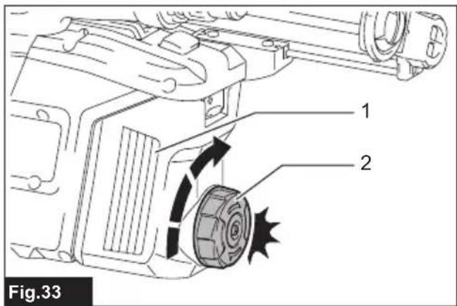
text_image
1 2 Fig.33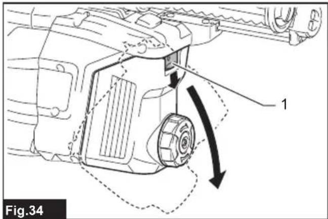
text_image
Fig.34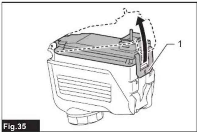
natural_image
Technical line drawing of a battery casing with internal components and an arrow indicating motion (no text or symbols)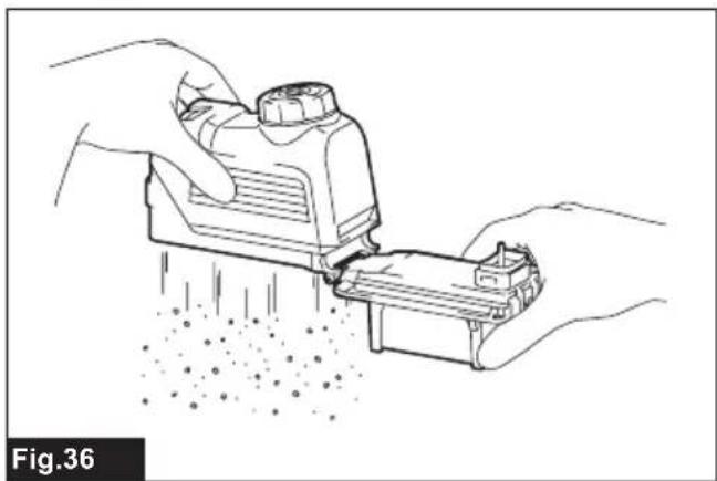
natural_image
Illustration of hands using a tool to remove particles from a device (no text or symbols)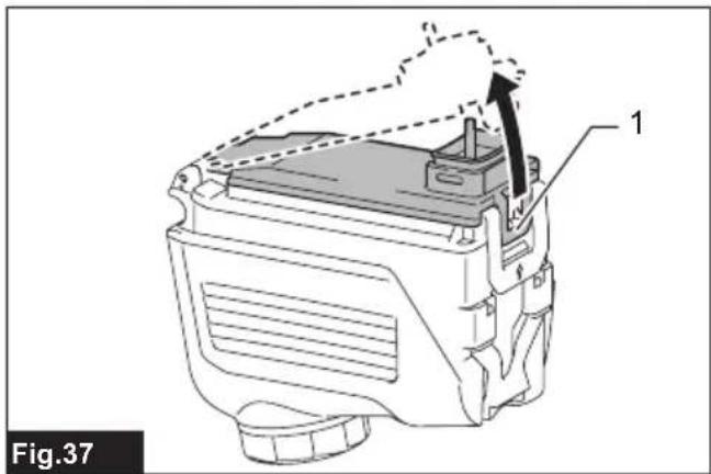
natural_image
Technical line drawing of a mechanical component with labeled parts (no text or symbols beyond label)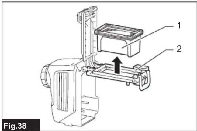
text_image
Fig.38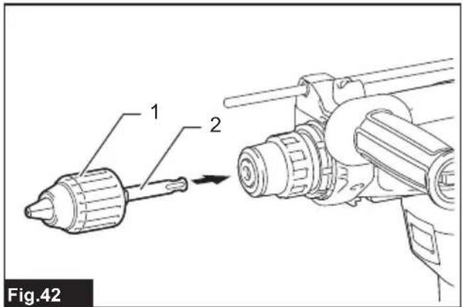
text_image
Fig.42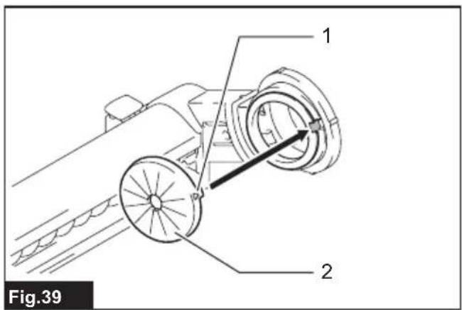
text_image
Fig.39 1 2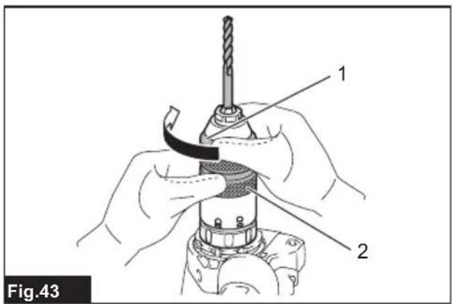
text_image
Fig.43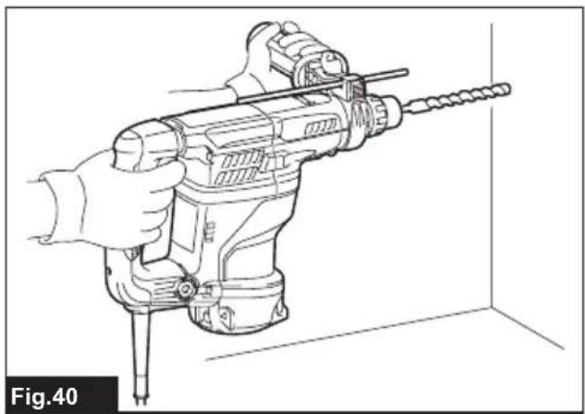
natural_image
Line drawing of a hand holding a drill bit with a screwdriver, shown in perspective view (no text or symbols)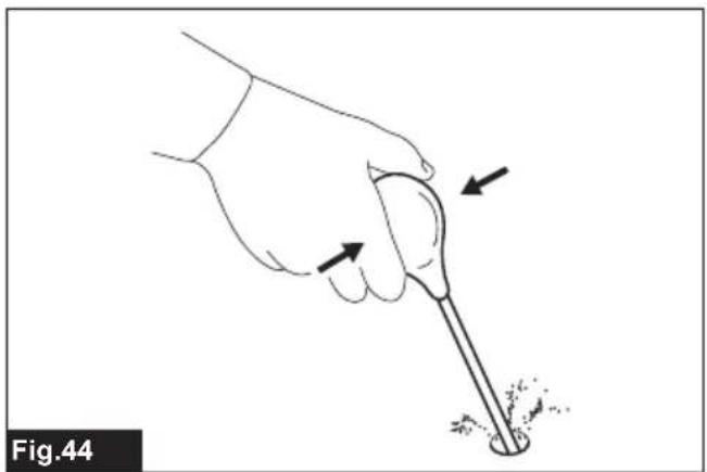
natural_image
Illustration of a hand holding a tool with arrows indicating motion or force direction (no text or symbols)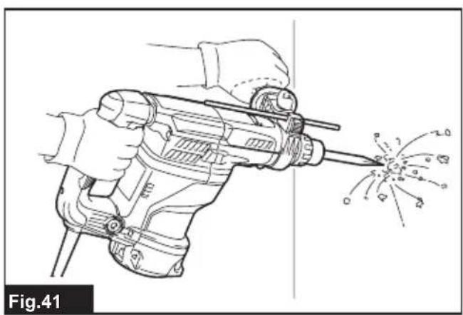
natural_image
Line drawing of a hand using a drill bit to trigger an explosion (no text or symbols)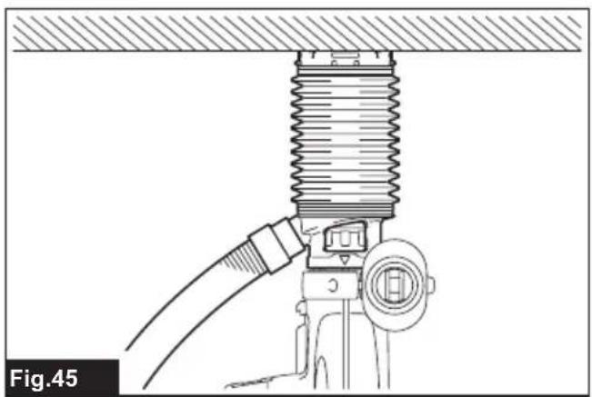
natural_image
Technical diagram of a mechanical assembly with coiled spring and connecting pipe (no text or symbols)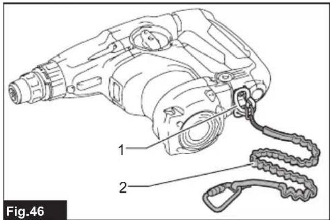
text_image
Fig.46 1 2SPECIFICATIONS
| Model: HR3011FC HR3012FC HR3001C | ||||
| Capacities Concrete 30 mm | ||||
| Core bit 80 mm | ||||
| Diamond core bit (dry type) 80 mm | ||||
| Steel 13 mm | ||||
| Wood 32 mm | ||||
| No load speed 0 - 840 min | -1 | |||
| Blows per minute 0 - 4,500 min | -1 | |||
| Overall length 369 mm 386 mm 369 mm | ||||
| Net weight | 4.4 - 4.8 kg | 4.5 - 4.7 kg | 4.1 - 4.5 kg | |
| Safety class | ☐/II | |||
Optional accessory
| Model: | DX10 (For HR3011FC) | DX11 (For HR3012FC) |
| Applicable workpiece and workmode | for concrete drilling only(not for metal or wood, and not for core drilling or chiseling) | |
| Suction performance | 350 l/min | |
| Operating stroke | Up to 190 mm | |
| Suitable drill bit | Up to 265 mm | |
| Net weight | 1.2 kg | |
• Due to our continuing program of research and development, the specifications herein are subject to change without notice.
• Specifications may differ from country to country.
• The weight may differ depending on the attachment(s). The lightest and heaviest combinations, according to EPTA-Procedure 01/2014, are shown in the table.
Intended use
The tool is intended for hammer drilling and drilling in brick, concrete and stone as well as for chiselling work. It is also suitable for drilling without impact in wood, metal, ceramic and plastic.
Power supply
The tool should be connected only to a power supply of the same voltage as indicated on the nameplate, and can only be operated on single-phase AC supply. They are double-insulated and can, therefore, also be used from sockets without earth wire.
Noise
The typical A-weighted noise level determined according to EN62841-2-6:
Model HR3011FC
Sound pressure level ( L_pA ): 93 dB (A) Sound power level ( L_WA ): 101 dB (A) Uncertainty (K): 3 dB (A)
Model HR3012FC
Sound pressure level ( L_pA ): 94 dB(A) Sound power level ( L_WA ): 102 dB (A) Uncertainty (K): 3 dB(A)
Model HR3001C
Sound pressure level ( L_pA ): 95 dB(A) Sound power level ( L_WA ): 103 dB (A) Uncertainty (K): 3 dB(A)
Model HR3011FC with DX10
Sound pressure level ( L_pA ): 96 dB(A) Sound power level ( L_WA ): 104 dB (A) Uncertainty (K): 3 dB(A)
Model HR3012FC with DX11
Sound pressure level ( L_pA ): 96 dB(A) Sound power level ( L_WA ): 104 dB (A) Uncertainty (K): 3 dB(A)
NOTE: The declared noise emission value(s) has been measured in accordance with a standard test method and may be used for comparing one tool with another.
NOTE: The declared noise emission value(s) may also be used in a preliminary assessment of exposure.
WARNING: Wear ear protection.
⚠ WARNING: The noise emission during actual use of the power tool can differ from the declared value(s) depending on the ways in which the tool is used especially what kind of workpiece is processed.
⚠ WARNING: Be sure to identify safety measures to protect the operator that are based on an estimation of exposure in the actual conditions of use (taking account of all parts of the operating cycle such as the times when the tool is switched off and when it is running idle in addition to the trigger time).
Vibration
The following table shows the vibration total value (tri-axial vector sum) determined according to applicable standard.
Model HR3011FC
| Work mode Vibration emission | Uncertainty (K) | Applicable standard / Test condition |
| Hammer drilling into concrete ( a_h, HD ) | 10.8 m/s ^2 | 1.5 m/s ^2 EN62841-2-6 |
| Hammer drilling into concrete with DX10 ( a_h, HD ) | 10.4 m/s ^2 | 1.5 m/s ^2 EN62841-2-6 |
| Chiselling ( a_h, CHeq ) | 9.7 m/s ^2 | 1.5 m/s ^2 EN62841-2-6 |
Model HR3012FC
| Work mode Vibration emission | Uncertainty (K) | Applicable standard / Test condition | |
| Hammer drilling into concrete ( a_h, HD ) | 10.5 m/s^2 | 1.5 m/s^2 | EN62841-2-6 |
| Hammer drilling into concrete with DX11 ( a_h, HD ) | 10.0 m/s^2 | 1.5 m/s^2 | EN62841-2-6 |
| Chiselling ( a_h, CHeq ) | 8.2 m/s^2 | 1.5 m/s^2 | EN62841-2-6 |
Model HR3001C
| Work mode Vibration emission | Uncertainty (K) | Applicable standard / Test condition |
| Hammer drilling into concrete ( a_n, HD ) | 12.2 m/s ^2 | 1.5 m/s ^2 EN62841-2-6 |
| Chiselling ( a_n, CHeq ) | 10.4 m/s ^2 | 1.5 m/s ^2 EN62841-2-6 |
Only for model HR3011FC / HR3012FC
To optimize working efficiency, we recommend the following:
- Apply feed force to the switch handle (main handle).
- Use the side grip (auxiliary handle) to withstand reaction torque and keep balance of the tool. This may reduce the vibration total emission values.
NOTE: The declared vibration total value(s) has been measured in accordance with a standard test method and may be used for comparing one tool with another.
NOTE: The declared vibration total value(s) may also be used in a preliminary assessment of exposure.
WARNING: The vibration emission during actual use of the power tool can differ from the declared value(s) depending on the ways in which the tool is used especially what kind of workpiece is processed.
WARNING: Be sure to identify safety measures to protect the operator that are based on an estimation of exposure in the actual conditions of use (taking account of all parts of the operating cycle such as the times when the tool is switched off and when it is running idle in addition to the trigger time).
Declarations of Conformity
For European countries only
The Declarations of conformity are included in Annex A to this instruction manual.
SAFETY WARNINGS
General power tool safety warnings
⚠ WARNING Read all safety warnings, instructions, illustrations and specifications provided with this power tool. Failure to follow all instructions listed below may result in electric shock, fire and/or serious injury.
Save all warnings and instructions for future reference.
The term "power tool" in the warnings refers to your mains-operated (corded) power tool or battery-operated (cordless) power tool.
ROTARY HAMMER SAFETY WARNINGS
Safety instructions for all operations
- Wear ear protectors. Exposure to noise can cause hearing loss.
- Use auxiliary handle(s), if supplied with the tool. Loss of control can cause personal injury.
- Hold the power tool by insulated gripping surfaces, when performing an operation where the cutting accessory may contact hidden wiring or its own cord. Cutting accessory contacting
a "live" wire may make exposed metal parts of the power tool "live" and could give the operator an electric shock.
Safety instructions when using long drill bits with rotary hammers
- Always start drilling at low speed and with the bit tip in contact with the workpiece. At higher speeds, the bit is likely to bend if allowed to rotate freely without contacting the workpiece, resulting in personal injury.
- Apply pressure only in direct line with the bit and do not apply excessive pressure. Bits can bend, causing breakage or loss of control, resulting in personal injury.
Additional safety warnings
- Wear a hard hat (safety helmet), safety glasses and/or face shield. Ordinary eye or sun glasses are NOT safety glasses. It is also highly recommended that you wear a dust mask and thickly padded gloves.
- Be sure the bit is secured in place before operation.
- Under normal operation, the tool is designed to produce vibration. The screws can come loose easily, causing a breakdown or accident. Check tightness of screws carefully before operation.
- In cold weather or when the tool has not been used for a long time, let the tool warm up for a while by operating it under no load. This will loosen up the lubrication. Without proper warm-up, hammering operation is difficult.
- Always be sure you have a firm footing. Be sure no one is below when using the tool in high locations.
- Hold the tool firmly with both hands.
- Keep hands away from moving parts.
- Do not leave the tool running. Operate the tool only when hand-held.
- Do not point the tool at any one in the area when operating. The bit could fly out and injure someone seriously.
- Do not touch the bit, parts close to the bit, or workpiece immediately after operation; they may be extremely hot and could burn your skin.
- Some material contains chemicals which may be toxic. Take caution to prevent dust inhalation and skin contact. Follow material supplier safety data.
- Do not touch the power plug with wet hands.
SAVE THESE INSTRUCTIONS.
WARNING: DO NOT let comfort or familiarity with product (gained from repeated use) replace strict adherence to safety rules for the subject product. MISUSE or failure to follow the safety rules stated in this instruction manual may cause serious personal injury.
FUNCTIONAL DESCRIPTION
CAUTION: Always be sure that the tool is switched off and unplugged before adjusting or checking function on the tool.
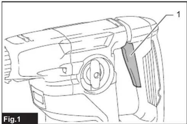
Switch action
CAUTION: Before plugging in the tool, always check to see that the switch trigger actuates properly and returns to the "OFF" position when released.
To start the tool, simply pull the switch trigger. Tool speed is increased by increasing pressure on the switch trigger. Release the switch trigger to stop.
▶ Fig.1: 1. Switch trigger
Lighting up the front lamp
For HR3011FC, HR3012FC only
⚠️ CAUTION: Do not look in the light or see the source of light directly.
To turn on the lamp, pull the switch trigger. Release the switch trigger to turn it off.
▶ Fig.2: 1. Lamp
NOTE: Use a dry cloth to wipe the dirt off the lens of the lamp. Be careful not to scratch the lens of the lamp, or it may lower the illumination.
Reversing switch action
⚠️ CAUTION: Always check the direction of rotation before operation.
⚠️ CAUTION: Use the reversing switch only after the tool comes to a complete stop. Changing the direction of rotation before the tool stops may damage the tool.
NOTICE: When changing the direction of rotation, be sure to fully set the reversing switch to A side or B side. Otherwise, when the switch trigger is pulled, the motor may not rotate or the tool may not work properly.
This tool has a reversing switch to change the direction of rotation. Move the reversing switch lever to the position A side for clockwise rotation or to the position B side for counterclockwise rotation.
▶ Fig.3: 1. Reversing switch lever
Changing the quick change chuck for SDS-plus
For HR3012FC only
The quick change chuck for SDS-plus can be easily exchanged for the quick change drill chuck.
Removing the quick change chuck for SDS-plus
⚠️CAUTION: Before removing the quick change chuck for SDS-plus, be sure to remove the bit.
Grasp the change cover of the quick change chuck for SDS-plus and turn in the direction of the arrow until the change cover line moves from the symbol to the symbol. Pull forcefully in the direction of the arrow.
▶ Fig.4: 1. Quick change chuck for SDS-plus 2. Change cover 3. Change cover line
Installing the quick change drill chuck
Check the line of the quick change drill chuck shows the symbol. Grasp the change cover of the quick change drill chuck and set the line to the symbol. Place the quick change drill chuck on the spindle of the tool. Grasp the change cover of the quick change drill chuck and turn the change cover line to the symbol until a click can clearly be heard.
▶ Fig.5: 1. Quick change drill chuck 2. Spindle 3. Change cover line 4. Change cover
Selecting the action mode
NOTICE: Do not rotate the action mode changing knob when the tool is running. The tool will be damaged.
NOTICE: To avoid rapid wear on the mode change mechanism, be sure that the action mode changing knob is always positively located in one of the three action mode positions.
Rotation with hammering
For drilling in concrete, masonry, etc., rotate the action mode changing knob to the symbol. Use a tungsten-carbide tipped bit (optional accessory).
▶ Fig.6: 1. Rotation with hammering 2. Action mode changing knob
Rotation only
For drilling in wood, metal or plastic materials, rotate the action mode changing knob to the symbol. Use a twist drill bit or wood drill bit.
▶ Fig.7: 1. Rotation only
Hammering only
For chipping, scaling or demolition operations, rotate the action mode changing knob to the symbol. Use a bull point, cold chisel, scaling chisel, etc.
▶ Fig.8: 1. Hammering only
Torque limiter
NOTICE: As soon as the torque limiter actuates, switch off the tool immediately. This will help prevent premature wear of the tool.
NOTICE: Drill bits such as hole saw, which tend to pinch or catch easily in the hole, are not appropriate for this tool. This is because they will cause the torque limiter to actuate too frequently.
The torque limiter will actuate when a certain torque level is reached. The motor will disengage from the output shaft. When this happens, the drill bit will stop turning.
Electronic function
The tool is equipped with the electronic functions for easy operation.
- Constant speed control The speed control function provides the constant rotation speed regardless of load conditions.
Air duct
For HR3011FC, HR3012FC only
CAUTION: Do not put your finger into the air duct or do not insert any other object into the air duct. Otherwise you may get injured or the tool may get damaged.
The air duct is to connect to the dust collection system. When using the dust collection system, read the section about the dust collection system.
▶ Fig.9: 1. Air duct
ASSEMBLY
⚠️ CAUTION: Always be sure that the tool is switched off and unplugged before carrying out any work on the tool.
Side grip (auxiliary handle)
⚠️ CAUTION: Always use the side grip to ensure safe operation.
CAUTION: After installing or adjusting the side grip, make sure that the side grip is firmly secured.
To install the side grip, follow the steps below.
- Loosen the thumb screw on the side grip.
▶ Fig.10: 1. Thumb screw
- Attach the side grip while pressing the thumb screw so that the grooves on the grip fit in the protrusions on the tool barrel.
▶ Fig.11: 1. Thumb screw
- Tighten the thumb screw to secure the grip. The grip can be fixed at desired angle.
Grease
Coat the shank end of the drill bit beforehand with a small amount of grease (about 0.5 - 1 g). This chuck lubrication assures smooth action and longer service life.
Installing or removing drill bit
Clean the shank end of the drill bit and apply grease before installing the drill bit.
▶ Fig.12: 1. Shank end 2. Grease
Insert the drill bit into the tool. Turn the drill bit and push it in until it engages.
After installing the drill bit, always make sure that the drill bit is securely held in place by trying to pull it out.
▶ Fig.13: 1. Drill bit
To remove the drill bit, pull the chuck cover down all the way and pull the drill bit out.
▶ Fig.14: 1. Drill bit 2. Chuck cover
Chisel angle (when chipping, scaling or demolishing)
The chisel can be secured at the desired angle. To change the chisel angle, rotate the action mode changing knob to the O symbol. Turn the chisel to the desired angle.
▶ Fig.15: 1. Action mode changing knob
Rotate the action mode changing knob to the Ⓥ symbol. Then make sure that the chisel is securely held in place by turning it slightly.
Depth gauge
The depth gauge is convenient for drilling holes of uniform depth.
Press and hold the lock button, and then insert the depth gauge into the hex hole. Make sure that the toothed side of the depth gauge faces the marking.
▶ Fig.16: 1. Depth gauge 2. Lock button 3. Marking 4. Toothed side
Adjust the depth gauge by moving it back and forth while pressing the lock button. After the adjustment, release the lock button to lock the depth gauge.
NOTE: Make sure that the depth gauge does not touch the main body of the tool when attaching it.
Dust cup
Optional accessory
Use the dust cup to prevent dust from falling over the tool and on yourself when performing overhead drilling operations. Attach the dust cup to the bit as shown in the figure. The size of bits which the dust cup can be attached to is as follows.
| Model Bit diameter | |
| Dust cup 5 6 mm - 14.5 mm | |
| Dust cup 9 12 mm - 16 mm |
▶ Fig.17: 1. Dust cup
Dust cup set
Optional accessory
For Models HR3011FC, HR3001C
NOTICE: When using the dust cup set in HR3011FC, HR3001C, the spacer is also requied.
Before installing the dust cup set, remove the bit from the tool if installed.
Attach the spacer to the dust cup set. △ symbol on the dust cup is aligned with the groove in the spacer.
▶ Fig.18: 1. Spacer 2. △ symbol 3. Groove
Install the dust cup set with the spacer on the tool so that the symbol on the dust cup is aligned with the groove in the tool.
▶ Fig.19: 1. △ symbol 2. Groove
To remove the dust cup set, remove the bit while pulling the chuck cover in the direction of the arrow.
▶ Fig.20: 1. Bit 2. Chuck cover
Hold the spacer and pull it out.
▶ Fig.21
For Model HR3012FC
Before installing the dust cup set, remove the bit from the tool if installed.
Install the dust cup set on the tool so that the symbol on the dust cup is aligned with the groove in the tool.
▶ Fig.22: 1. △ symbol 2. Groove
To remove the dust cup set, remove the bit while pulling the chuck cover in the direction of the arrow.
▶ Fig.23: 1. Bit 2. Chuck cover
Hold the root of dust cup and pull it out.
▶ Fig.24
NOTE: If you connect a vacuum cleaner to the dust cup set, remove the dust cap before connecting it.
▶ Fig.25: 1. Dust cap
NOTE: If the cap comes off from the dust cup, attach it with its printed side facing up so that groove on the cap fits in the inside periphery of the attachment.
▶ Fig.26
Tool hanger
Optional accessory
WARNING: Do not use damaged tool hanger and screw.
⚠ WARNING: Use the screw provided with the tool hanger only.
WARNING: Before using the tool hanger, check for damages, cracks or deformations, and make sure that the screw is tightened.
⚠️ CAUTION: Install or remove the tool hanger on a stable table or surface.
The tool hanger is intended for connecting the lanyard
(tether strap). To install the tool hanger to the tool, follow the steps below.
- Disconnect the plug from the power source.
- Insert the projections of the tool hanger into the holes on the tool.
- Tighten the screws firmly.
▶ Fig.27: 1. Tool hanger 2. Hole 3. Projection 4. Screw
For HR3011FC, HR3012FC only
Optional accessory
The dust collection system is designed to collect dusts effectively when the concrete drilling operation.
▶ Fig.28: 1. Dust collection system
⚠️CAUTION: Make sure that the tool is switched off and unplugged before carrying out any work on the tool. Failure to do so may result in personal injury from accidental start-up.
⚠️CAUTION: Always attach the filter to the dust collection system. Failure to do so cause dust inhalation.
⚠️CAUTION: Check that the filter is not damaged. Failure to do so may cause dust inhalation.
NOTICE: Do not use the dust collection system for core drilling or chiseling. The dust collection system is intended for drilling only.
NOTICE: Do not use the dust collection system for metal or wood. The dust collection system is intended for concrete only.
NOTICE: Do not use the dust collection system for drilling in wet concrete or use this system in wet environment. Failure to do so may cause malfunction.
NOTE: The dust collection system collects the generated dust at a considerable rate, but not all dust can be collected.
Installing or removing the dust collection system
NOTICE: Before installing the dust collection system, clean the joint parts of the tool and the dust collection system.
Foreign matters on the joint parts may cause it difficult to install the dust collection system. Particularly the foreign matters on the electrical interface may cause malfunction.
If any dust remains on the air duct, the dust comes into the tool and causes jam in the airflow or breakage of the tool.
Hook the dust collection system on the tool, and then
insert the dust collection system all the way, until it locks in place with a little double click.
After that, make sure that the dust collection system is securely installed.
When removing the dust collection system, press the lock-off button.
▶ Fig.29: 1. Air duct
▶ Fig.30: 1. Lock-off button
Adjusting the nozzle position of the dust collection system
CAUTION: Do not point the nozzle at yourself or others when releasing the nozzle by pushing the guide adjustment button.
Push in the guide while pushing the guide adjustment button, and then release the guide adjustment button at the desired position.
▶ Fig.31: 1. Guide 2. Guide adjustment button
Adjusting the drilling depth of the dust collection system
Slide the depth adjustment button to the desired position while pushing it. The distance (A) is the drilling depth.
▶ Fig.32: 1. Depth adjustment button
Beating dust on the filter
⚠️ CAUTION: Do not turn the dial on the dust case while the dust case is removed from the dust collection system. Doing so may cause dust inhalation.
CAUTION: Always switch off the tool when turning the dial on the dust case. Turning the dial while the tool is running may result in the loss of control of the tool.
By beating the dust on the filter inside the dust case, you can keep the vacuum efficiency and also reduce the number of times to dispose of the dust.
Turn the dial on the dust case three times after collecting every 50,000 mm ^3 of dust or when you feel the vacuum performance declined.
NOTE: 50,000 mm ^3 of dust equivalents to drilling 10 holes of 10 mm and 65 mm depth (14 holes of 3/8" and 2" depth).
▶ Fig.33: 1. Dust case 2. Dial
Disposing of dust
⚠️CAUTION: Wear dust mask when disposing of dust.
⚠️CAUTION: Empty the dust case regularly before the dust case becomes full. Failure to do so may decrease the dust collection performance, and then cause dust inhalation.
⚠️CAUTION: Replace the filter with new one after approximately 200 times of dust fulfillment as a guide. A clogged filter decreases dust collection performance, and then cause dust inhalation.
NOTICE: When cleaning the filter, tap the case of the filter gently by hand to remove dust. Do not tap the filter directly; touch the filter with brush or similar; or blow compressed air on the filter. Doing so may damage the filter.
- Remove the dust case while pressing down the lever of the dust case.
▶ Fig.34: 1. Lever - Open the cover of the dust case.
▶ Fig.35: 1. Cover - Dispose of the dust, and then clean the filter.
▶ Fig.36
Replacing filter of dust case
- Remove the dust case while pressing down the lever of the dust case. (Refer to the section for disposing of dust.)
- Open the filter cover of the dust case.
▶ Fig.37: 1. Filter cover
- Remove the filter from the filter case.
▶ Fig.38: 1. Filter 2. Filter case - Attach a new filter to the filter case, and then attach the filter cover.
- Close the cover of the dust case, and then attach the dust case to the dust collection system.
Replacing sealing cap
If the sealing cap is worn out, the performance of the dust collection decreases. Replace it if it is worn out. Remove the sealing cap, and then attach a new one with its protrusion facing upward.
▶ Fig.39: 1. Protrusion 2. Sealing cap
OPERATION
CAUTION: Always use the side grip (auxiliary handle) and firmly hold the tool by both side grip and switch handle during operations.
⚠️ CAUTION: Always make sure that the workpiece is secured before operation.
⚠️ CAUTION: Do not pull the tool out forcibly even the bit gets stuck. Loss of control may cause injury.
CAUTION: For HR3011FC, HR3012FC only
Before using the dust collection system with the tool, read the section about the dust collection system.
▶ Fig.40
Hammer drilling operation
CAUTION: There is tremendous and sudden twisting force exerted on the tool/drill bit at the time of hole break-through, when the hole becomes clogged with chips and particles, or when striking reinforcing rods embedded in the concrete. Always use the side grip (auxiliary handle) and firmly hold the tool by both side grip and switch handle during operations. Failure to do so may result in the loss of control of the tool and potentially severe injury.
Set the action mode changing knob to the symbol. Position the drill bit at the desired location for the hole, then pull the switch trigger. Do not force the tool. Light pressure gives best results. Keep the tool in position and prevent it from slipping away from the hole.
Do not apply more pressure when the hole becomes clogged with chips or particles. Instead, run the tool at an idle, then remove the drill bit partially from the hole. By repeating this several times, the hole will be cleaned out and normal drilling may be resumed.
NOTE: Eccentricity in the drill bit rotation may occur while operating the tool with no load. The tool automatically centers itself during operation. This does not affect the drilling precision.
Chipping/Scaling/Demolition
Set the action mode changing knob to the symbol. Hold the tool firmly with both hands. Turn the tool on and apply slight pressure on the tool so that the tool will not bounce around, uncontrolled. Pressing very hard on the tool will not increase the efficiency.
▶ Fig.41
Drilling in wood or metal
⚠️CAUTION: Hold the tool firmly and exert care when the drill bit begins to break through the workpiece. There is a tremendous force exerted on the tool/drill bit at the time of hole break through.
⚠CAUTION: A stuck drill bit can be removed simply by setting the reversing switch to reverse rotation in order to back out. However, the tool may back out abruptly if you do not hold it firmly.
⚠️CAUTION: Always secure workpieces in a vise or similar hold-down device.
NOTICE: Never use "rotation with hammering" when the drill chuck is installed on the tool. The drill chuck may be damaged.
Also, the drill chuck will come off when reversing the tool.
NOTICE: Pressing excessively on the tool will not speed up the drilling. In fact, this excessive pressure will only serve to damage the tip of your drill bit, decrease the tool performance and shorten the service life of the tool.
Set the action mode changing knob to the symbol.
For Models HR3011FC, HR3001C
Optional accessory
Attach the chuck adapter to a keyless drill chuck to which 1/2"-20 size screw can be installed, and then install them to the tool. When installing it, refer to the section "Installing or removing drill bit".
▶ Fig.42: 1. Keyless drill chuck 2. Chuck adapter
For Model HR3012FC
Use the quick change drill chuck as standard equipment. When installing it, refer to "changing the quick change chuck for SDS-plus".
Hold the ring and turn the sleeve counterclockwise to open the chuck jaws. Place the bit in the chuck as far as it will go. Hold the ring firmly and turn the sleeve clockwise to tighten the chuck.
▶ Fig.43: 1. Sleeve 2. Ring
To remove the bit, hold the ring and turn the sleeve counterclockwise.
Diamond core drilling
NOTICE: If performing diamond core drilling operations using "rotation with hammering" action, the diamond core bit may be damaged.
When performing diamond core drilling operations, always set the action mode changing knob to the position to use "rotation only" action.
Blow-out bulb
Optional accessory
After drilling the hole, use the blow-out bulb to clean the dust out of the hole.
▶ Fig.44
Using dust cup set
Optional accessory
Fit the dust cup set against the ceiling when operating the tool.
▶ Fig.45
NOTICE: Do not use the dust cup set when drilling in metal or similar. It may damage the dust cup set due to the heat produced by small metal dust or similar.
NOTICE: Do not install or remove the dust cup set with the drill bit installed in the tool. It may damage the dust cup set and cause dust leak.
Connecting lanyard (tether strap) to tool hanger
Safety warnings specific for use at height Read all safety warnings and instructions. Failure to follow the warnings and instructions may result in serious injury.
- Always keep the tool tethered when working "at height". Maximum lanyard length is 2 m. The maximum permissible fall height for lanyard (tether strap) must not exceed 2 m.
- Use only with lanyards appropriate for this tool type and rated for at least 7.5 kg.
- Do not anchor the tool lanyard to anything on your body or on movable components. Anchor the tool lanyard to a rigid structure that can withstand the forces of a dropped tool.
- Make sure the lanyard is properly secured at each end prior to use.
- Inspect the tool and lanyard before each use for damage and proper function (including fabric and stitching). Do not use if damaged or not functioning properly.
- Do not wrap lanyards around or allow them to come in contact with sharp or rough edges.
- Fasten the other end of the lanyard outside the working area so that a falling tool is held securely.
- Attach the lanyard so that the tool will move away from the operator if it falls. Dropped tools will swing on the lanyard, which could cause injury or loss of balance.
- Do not use near moving parts or running machinery. Failure to do so may result in a crush or entanglement hazard.
- Do not carry the tool by the attachment device or the lanyard.
- Only transfer the tool between your hands while you are properly balanced.
- Do not attach lanyards to the tool in a way that keeps switches or trigger-lock (if supplied) from operating properly.
- Avoid getting tangled in the lanyard.
- Keep lanyard away from the drilling area of the tool.
- Use multi-action and screw gate type carabineers. Do not use single action spring clip
carabineers.
- In the event the tool is dropped, it must be tagged and removed from service, and should be inspected by a Makita Factory or Authorized Service Center.
▶ Fig.46: 1. Tool hanger 2. Lanyard (tether strap)
MAINTENANCE
⚠️CAUTION: Always be sure that the tool is switched off and unplugged before attempting to perform inspection or maintenance.
NOTICE: Never use gasoline, benzine, thinner, alcohol or the like. Discoloration, deformation or cracks may result.
To maintain product SAFETY and RELIABILITY, repairs, any other maintenance or adjustment should be performed by Makita Authorized or Factory Service Centers, always using Makita replacement parts.
OPTIONAL ACCESSORIES
⚠️CAUTION: These accessories or attachments are recommended for use with your Makita tool specified in this manual. The use of any other accessories or attachments might present a risk of injury to persons. Only use accessory or attachment for its stated purpose.
If you need any assistance for more details regarding these accessories, ask your local Makita Service Center.
- Carbide-tipped drill bits (SDS-Plus carbide-tipped bits)
- Core bit
- Bull point
- Diamond core bit
- Cold chisel
- Scaling chisel
- Grooving chisel
- Chuck adapter
• Keyless drill chuck - Bit grease
- Depth gauge
- Blow-out bulb
- Dust cup
- Dust cup set
- Spacer (for HR3011FC, HR3001C)
- Dust collection system (for HR3011FC, HR3012FC)
- Tool hanger
NOTE: Some items in the list may be included in the tool package as standard accessories. They may differ from country to country.
SPÉCIFICATIONS
▶ Fig.7: 1. Rotation uniquement
▶ Fig.43: 1. Manchon 2. Bague
▶ Abb.19: 1. Symbol △ 2. Nut
▶ Abb.22: 1. △ Symbol 2. Nut
▶ Abb.25: 1. Staubkappe
▶ Abb.28: 1. Staubabsaugsystem
▶ Abb.42: 1. Schlüsselloses Bohrfutter
- Futteradapter
Für Modell HR3012FC
⚠ WAARSCHUWING: Draag gehoorbescherming.
VEILIGHEIDSWAAR- SCHUWINGEN
▶ Fig.17: 1. Stofvanger
Stofvangerset
Optioneel accessoire
Voor de modellen HR3011FC, HR3001C
▶ Fig.25: 1. Stofdop
▶ Fig.28: 1. Stofopvangsysteem
▶ Fig.33: 1. Stofopvangdoos 2. Knop
Het stof weggooien
▶ Fig.43: 1. Bus 2. Ring
OPTIONELE ACCESSOIRES
▶ Fig.20: 1. Broca 2. Tampa do mandril
▶ Fig.23: 1. Broca 2. Tampa do mandril
Kun for HR3011FC, HR3012FC
Kun for HR3011FC, HR3012FC
Kun for HR3011FC, HR3012FC
Ekstraudstyr
▶ Fig.43: 1. Muffe 2. Ring