SG1251 - Drill MAKITA - Free user manual and instructions
Find the device manual for free SG1251 MAKITA in PDF.

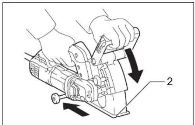
User questions about SG1251 MAKITA
0 question about this device. Answer the ones you know or ask your own.
Ask a new question about this device
Download the instructions for your Drill in PDF format for free! Find your manual SG1251 - MAKITA and take your electronic device back in hand. On this page are published all the documents necessary for the use of your device. SG1251 by MAKITA.
USER MANUAL SG1251 MAKITA
GB Wall Chaser Instruction Manual
natural_image
Line drawing of a mechanical power tool with handle and blade (no text or symbols)

natural_image
Technical line drawing of a mechanical assembly with no visible text or symbols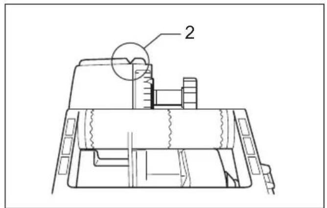
text_image
2015036 004497
1
text_image
Technical diagram showing mechanical assembly with labeled parts and directional arrows indicating movement or force
text_image
5 6015077 015038 4
3
natural_image
Technical line drawing of a mechanical component with labeled part '7' (no text or symbols beyond label)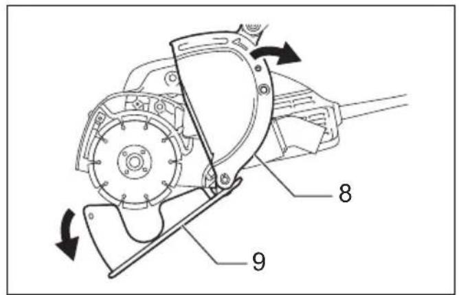
text_image
Technical diagram of a mechanical device with numbered parts and directional arrows indicating motion or assembly.015039 015040 6
5
text_image
1 10 116
7
015053
| Groove width: 30 mm | Groove width: 27 mm |
 |  |
| Groove width: 24 mm | Groove width: 21 mm |
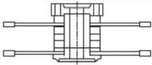 | 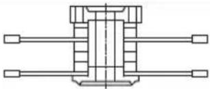 |
| Groove width: 18 mm | Groove width: 15 mm |
 |  |
| Groove width: 12 mm | Groove width: 9 mm |
 |  |
| Groove width: 6 mm | |
 |
text_image
1 10 11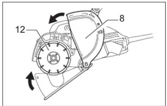
text_image
12 8015054 015047 10
9
text_image
7 15015042
11
text_image
16 17 18 17 16015043
12
text_image
19 20 21015046
text_image
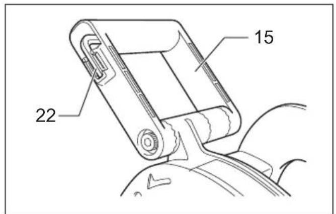
15 22004508
13 14
natural_image
Line drawing of a hand operating a mechanical device (no text or symbols present)15 16
natural_image
Illustration of hands operating a mechanical device with directional arrows indicating motion (no text or symbols)015076 015044
text_image
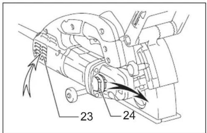
23 2417
015045
Explanation of general view
| 1 Shaft lock | 9 Tool base | 17 Cam |
| 2 N o t c h | 10 Lock nut | 18 Bolt (Long) |
| 3 S c a l e | 11 Lock nut wrench | 19 Dust nozzle |
| 4 Clamping screw | 12 Diamond wheel | 20 Vacuum cleaner |
| 5 Switch trigger | 13 Space ring 6 (6 mm thick) | 21 Hose |
| 6 Lock button / Lock-off button | 14 Space ring 3 (3 mm thick) | 22 Hex wrench |
| 7 B o l t | 15 Front handle | 23 Inhalation vent |
| 8 Blade case | 16 Bolt (Short) | 24 Exhaust vent |
SPECIFICATIONS
| Model SG1251 | |
| Wheel diameter 125 mm | |
| Max. wheel thickness 2.1 mm | |
| Rated speed 10,000 min | -1 |
| Spindle thread | M14 |
| Overall length | 350 mm |
| Net weight | 4.5 kg |
| Safety class | ☐/II |
- Due to our continuing program of research and development, the specifications herein are subject to change without notice.
- Specifications may differ from country to country.
• Weight according to EPTA-Procedure 01/2003
ENE026-1
Intended use
The tool is intended for cutting tracks in concrete walls or cutting in ferrous materials or concrete drainage channels with a diamond wheel but without using water.
ENF002-2
Power supply
The tool should be connected only to a power supply of the same voltage as indicated on the nameplate, and can only be operated on single-phase AC supply. They are double-insulated and can, therefore, also be used from sockets without earth wire.
GEA010-1
General Power Tool Safety Warnings
⚠ WARNING Read all safety warnings and all instructions. Failure to follow the warnings and instructions may result in electric shock, fire and/or serious injury.
Save all warnings and instructions for future reference.
GEB112-6
WALL CHASER SAFETY WARNINGS
-
The guard provided with the tool must be securely attached to the power tool and positioned for maximum safety, so the least amount of wheel is exposed towards the operator. Position yourself and bystanders away from the plane of the rotating wheel. The guard helps to protect operator from broken wheel fragments and accidental contact with wheel.
-
Use only diamond cut-off wheels for your power tool. Just because an accessory can be attached to your power tool, it does not assure safe operation.
- The rated speed of the accessory must be at least equal to the maximum speed marked on the power tool. Accessories running faster than their rated speed can break and fly apart.
- Wheels must be used only for recommended applications. For example: do not grind with the side of cut-off wheel. Abrasive cut-off wheels are intended for peripheral grinding, side forces applied to these wheels may cause them to shatter.
- Always use undamaged wheel flanges that are of correct diameter for your selected wheel. Proper wheel flanges support the wheel thus reducing the possibility of wheel breakage.
- The outside diameter and the thickness of your accessory must be within the capacity rating of your power tool. Incorrectly sized accessories cannot be adequately guarded or controlled.
- The arbour size of wheels and flanges must properly fit the spindle of the power tool. Wheels and flanges with arbour holes that do not match the mounting hardware of the power tool will run out of balance, vibrate excessively and may cause loss of control.
-
Do not use damaged wheels. Before each use, inspect the wheels for chips and cracks. If power tool or wheel is dropped, inspect for damage or install an undamaged wheel. After inspecting and installing the wheel, position yourself and bystanders away from the plane of the rotating wheel and run the power tool at maximum no load speed for one minute. Damaged wheels will normally break apart during this test time.
-
Wear personal protective equipment. Depending on application, use face shield, safety goggles or safety glasses. As appropriate, wear dust mask, hearing protectors, gloves and shop apron capable of stopping small abrasive or workpiece fragments. The eye protection must be capable of stopping flying debris generated by various operations. The dust mask or respirator must be capable of filtrating particles generated by your operation. Prolonged exposure to high intensity noise may cause hearing loss.
-
Keep bystanders a safe distance away from work area. Anyone entering the work area must wear personal protective equipment. Fragments of workpiece or of a broken wheel may fly away and cause injury beyond immediate area of operation.
-
Hold the power tool by insulated gripping surfaces only, when performing an operation where the cutting accessory may contact hidden wiring or its own cord. Cutting accessory contacting a "live" wire may make exposed metal parts of the power tool "live" and could give the operator an electric shock.
-
Position the cord clear of the spinning accessory. If you lose control, the cord may be cut or snagged and your hand or arm may be pulled into the spinning wheel.
-
Never lay the power tool down until the accessory has come to a complete stop. The spinning wheel may grab the surface and pull the power tool out of your control.
-
Do not run the power tool while carrying it at your side. Accidental contact with the spinning accessory could snag your clothing, pulling the accessory into your body.
-
Regularly clean the power tool's air vents. The motor's fan will draw the dust inside the housing and excessive accumulation of powdered metal may cause electrical hazards.
-
Do not operate the power tool near flammable materials. Sparks could ignite these materials.
-
Do not use accessories that require liquid coolants. Using water or other liquid coolants may result in electrocution or shock.
Kickback and related warnings
Kickback is a sudden reaction to a pinched or snagged rotating wheel. Pinching or snagging causes rapid stalling of the rotating wheel which in turn causes the uncontrolled power tool to be forced in the direction opposite of the wheel's rotation at the point of the binding.
For example, if an abrasive wheel is snagged or pinched by the workpiece, the edge of the wheel that is entering into the pinch point can dig into the surface of the material causing the wheel to climb out or kick out. The wheel may either jump toward or away from the operator, depending on direction of the wheel's movement at the point of pinching. Abrasive wheels may also break under these conditions.
Kickback is the result of power tool misuse and/or incorrect operating procedures or conditions and can be avoided by taking proper precautions as given below.
a) Maintain a firm grip on the power tool and position your body and arm to allow you to resist kickback forces. Always use auxiliary handle, if provided, for maximum control over kickback or torque reaction during start-up. The operator can control torque reactions or kickback forces, if proper precautions are taken.
b) Never place your hand near the rotating accessory. Accessory may kickback over your hand.
c) Do not position your body in line with the rotating wheel. Kickback will propel the tool in direction opposite to the wheel's movement at the point of snagging.
d) Use special care when working corners, sharp edges etc. Avoid bouncing and snagging the accessory. Corners, sharp edges or bouncing have a tendency to snag the rotating accessory and cause loss of control or kickback.
e) Do not attach a saw chain, woodcarving blade, segmented diamond wheel with a peripheral gap greater than 10 mm or toothed saw blade. Such blades create frequent kickback and loss of control.
f) Do not “jam” the wheel or apply excessive pressure. Do not attempt to make an excessive depth of cut. Overstressing the wheel increases the loading and susceptibility to twisting or binding of the wheel in the cut and the possibility of kickback or wheel breakage.
g) When wheel is binding or when interrupting a cut for any reason, switch off the power tool and hold the power tool motionless until the wheel comes to a complete stop. Never attempt to remove the wheel from the cut while the wheel is in motion otherwise kickback may occur. Investigate and take corrective action to eliminate the cause of wheel binding.
h) Do not restart the cutting operation in the workpiece. Let the wheel reach full speed and carefully re-enter the cut. The wheel may bind, walk up or kickback if the power tool is restarted in the workpiece.
i) Support panels or any oversized workpiece to minimize the risk of wheel pinching and kickback. Large workpieces tend to sag under their own weight. Supports must be placed under the workpiece near the line of cut and near the edge of the workpiece on both sides of the wheel.
j) Use extra caution when making a “pocket cut” into existing walls or other blind areas. The protruding wheel may cut gas or water pipes, electrical wiring or objects that can cause kickback.
- Before using a segmented diamond wheel, make sure that the diamond wheel has the peripheral gap between segments of 10 mm or less, only with a negative rake angle.
Additional Safety Warnings:
- Never attempt to cut with the tool held upside down in a vise. This can lead to serious accidents, because it is extremely dangerous.
- Some material contains chemicals which may be toxic. Take caution to prevent dust inhalation and skin contact. Follow material supplier safety data.
- Store wheels as per manufacturer recommendations. Improper storage may damage the wheels.
SAVE THESE INSTRUCTIONS.
WARNING:
DO NOT let comfort or familiarity with product (gained from repeated use) replace strict adherence to safety rules for the subject product. MISUSE or failure to follow the safety rules stated in this instruction manual may cause serious personal injury.
FUNCTIONAL DESCRIPTION
CAUTION:
• Always be sure that the tool is switched off and unplugged before adjusting or checking function on the tool.
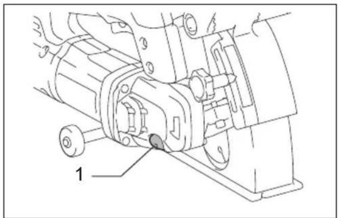
Shaft lock (Fig. 1)
CAUTION:
- Never actuate the shaft lock when the spindle is moving. The tool may be damaged.
Press the shaft lock to prevent spindle rotation when installing or removing accessories.
Sighting (Fig. 2)
There are notches on the front and rear of the base. This is helpful for an operator to follow a straight cutting line.
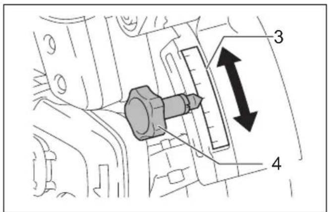
Adjusting the grooving depth (Fig. 3)
The grooving depth can be adjusted between 0 mm and 30 mm.
Loosen the clamping screw and adjust the pointer to your desired depth graduation on the scale.
Then tighten the clamping screw firmly.
Switch action (Fig. 4)
CAUTION:
- Before plugging in the tool, always check to see that the switch trigger actuates properly and returns to the "OFF" position when released.
For tool with lock button
CAUTION:
- Switch can be locked in "ON" position for ease of operator comfort during extended use. Apply caution when locking tool in "ON" position and maintain firm grasp on tool.
To start the tool, simply pull the switch trigger. Release the switch trigger to stop.
For continuous operation, pull the switch trigger, push in the lock button and then release the switch trigger.
To stop the tool from the locked position, pull the switch trigger fully, then release it.
For tool with lock-off button
CAUTION:
- Do not pull the switch trigger hard without pressing in the lock-off button. This can cause switch breakage.
To prevent the switch trigger from being accidentally pulled, a lock-off button is provided.
To start the tool, depress the lock-off button and pull the switch trigger. Release the switch trigger to stop.
For tool without lock button / lock-off button
To start the tool, simply pull the switch trigger. Release the switch trigger to stop.
Electronic function
The tools equipped with electronic function are easy to operate because of the following features.
Constant speed control
Electronic speed control for obtaining constant speed. Possible to get fine finish, because the rotating speed is kept constant even under load condition.
Soft start
Soft-start feature minimizes start-up shock, and makes the tool start smoothly.
Overload protector
When the tool would be employed over the admissible load, it will stop automatically to protect the motor and wheel. When the load will come to the admissible level again, the tool can be started automatically.
ASSEMBLY
CAUTION:
- Always be sure that the tool is switched off and unplugged before carrying out any work on the tool.
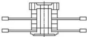
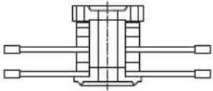
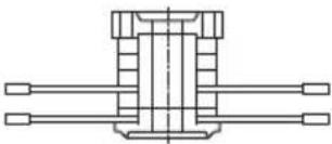
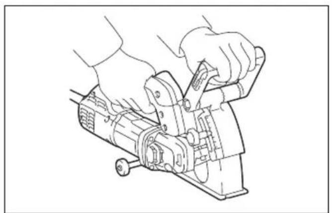
Removing the diamond wheels (Fig. 5, 6 & 7)
Loosen and remove the bolt with the hex wrench.
Open the blade case while holding the tool base.
NOTE:
- The tool base will open at a stroke by the spring force.
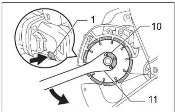
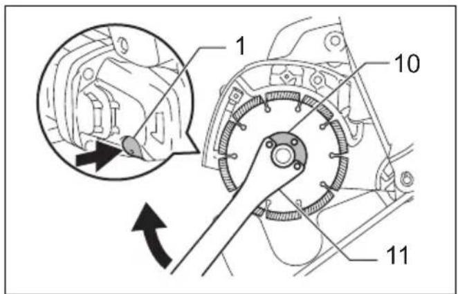
Rotate the diamond wheels while pressing the shaft lock until it engages.
Remove the lock nut by rotating it counterclockwise with the lock nut wrench.
Remove the diamond wheels and space rings.
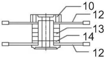
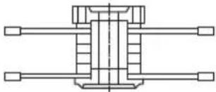
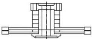
Adjusting the groove width (the distance between the two diamond wheels)
Adjust the grooving width by changing the number of the space rings as shown in the table. (Fig. 8)
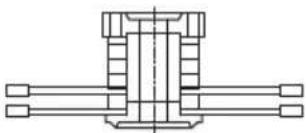
Installing the diamond wheels (Fig. 9 & 10)
Mount the diamond wheel carefully onto the spindle.
Align the directions of the arrow on the diamond wheel and the tool. Install space rings, the other diamond wheel and the lock nut.
Tighten the lock nut securely clockwise with the lock nut wrench while pressing the shaft lock.
Return the blade case and tool base to the original position and tighten the bolt to secure them.
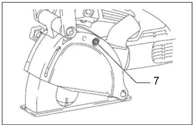
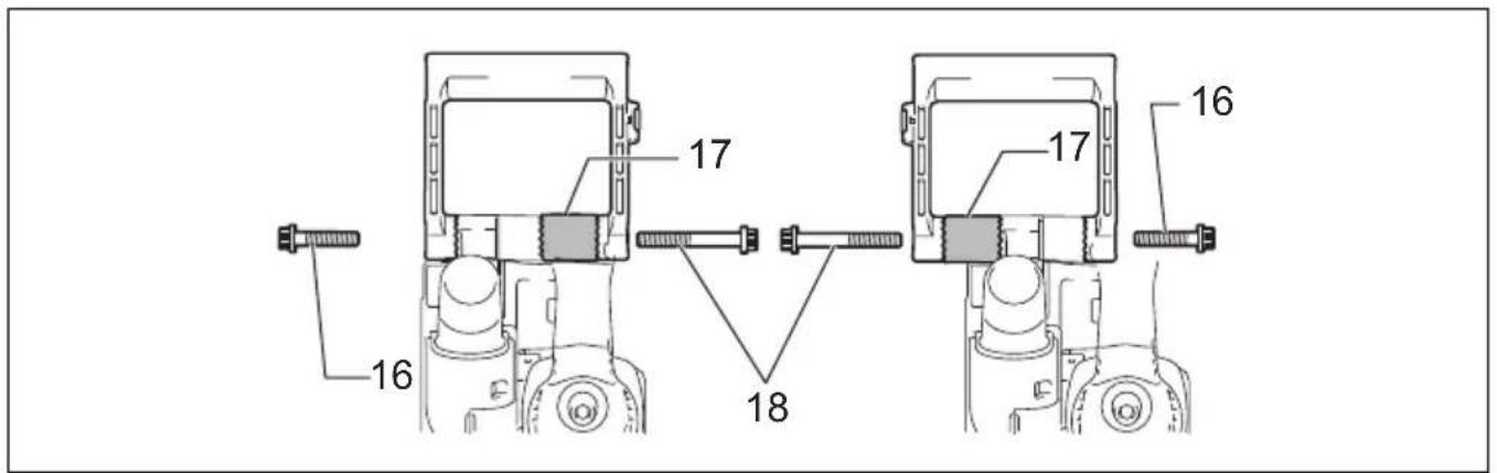
Adjusting the front handle angle (Fig. 11)
Loosen the two bolts on both sides of the front handle with the hex wrench. Move the front handle to your desired angle and tighten the two bolts firmly.
NOTE:
- When the handle cannot be moved easily, loosen the bolts furthermore.
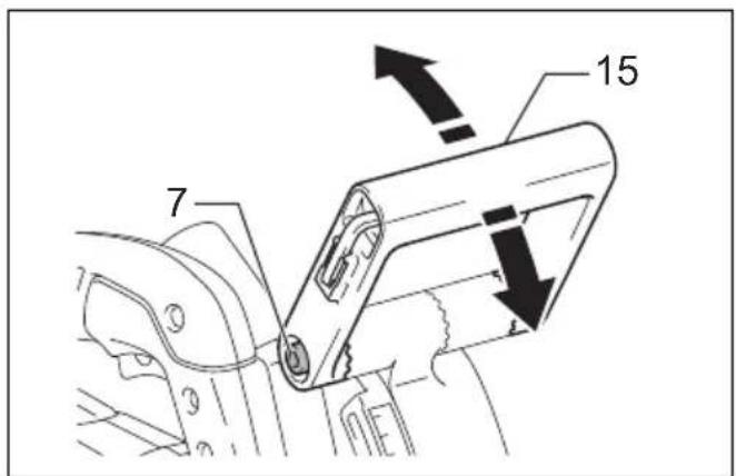
Shifting the front handle sideways (Fig. 12)
Remove the two bolts on both sides of the front handle with the hex wrench. Change the position of the cam. Insert the longer bolt to the side close to the cam and the shorter one to the opposite side. Tighten the two bolts firmly.
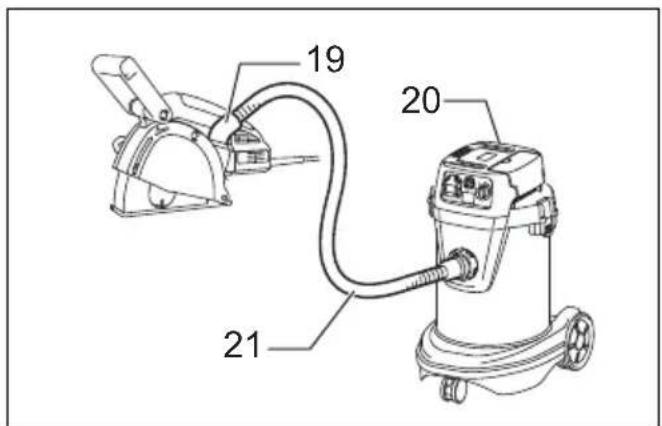
Connecting to vacuum cleaner (Fig. 13)
When using Makita dust collector, connect the hose for the vacuum cleaner directly to the dust nozzle.
NOTE:
- The dust nozzle can be rotated freely so that you can use it at any angle according to your operation.
Hex wrench storage (Fig. 14)
When not in use, store the hex wrench to keep it from being lost.
OPERATION
CAUTION:
- Be sure to pull the tool when cutting a workpiece.
- Use this tool for straight line cutting only. Cutting curves can cause stress cracks or fragmentation of the diamond wheels resulting in possible injury to persons in the vicinity.
- After operation, always switch off the tool and wait until the diamond wheels come to a complete stop before putting the tool down.
- Hold the tool firmly with one hand on the switch handle and the other hand on the front grip when performing the tool.
Hold the tool firmly with both hands. First keep the diamond wheels without making any contact with a workpiece. Then turn the tool on and wait until the diamond wheels attain full speed. (Fig. 15)
To cut a workpiece, pull the tool toward you (not by pushing away from you). Align the notch on the base with your cutting line. Push down the front handle gently until it stops and then pull the tool slowly. (Fig. 16)
Before finishing cutting operation and raising the tool, switch it off first. Wait until the diamond wheels stop completely and then raise the tool.
Remove the remaining portion between the two blade passages by other appropriate tools.
MAINTENANCE
CAUTION:
- Always be sure that the tool is switched off and unplugged before attempting to perform inspection or maintenance.
- Never use gasoline, benzine, thinner, alcohol or the like. Discoloration, deformation or cracks may result.
The tool and its air vents have to be kept clean. Regularly clean the tool's air vents or whenever the vents start to become obstructed. (Fig. 17)
Dressing diamond wheel
If the cutting action of the diamond wheel begins to diminish, use an old discarded coarse grit bench grinder wheel or concrete block to dress the diamond wheel. To do this, tightly secure the bench grinder wheel or concrete block and cut in it.
To maintain product SAFETY and RELIABILITY, repairs, carbon brush inspection and replacement, any other maintenance or adjustment should be performed by Makita Authorized Service Centers, always using Makita replacement parts.
OPTIONAL ACCESSORIES
CAUTION:
- These accessories or attachments are recommended for use with your Makita tool specified in this manual. The use of any other accessories or attachments might present a risk of injury to persons. Only use accessory or attachment for its stated purpose.
If you need any assistance for more details regarding these accessories, ask your local Makita Service Center.
- Diamond wheels
NOTE:
- Some items in the list may be included in the tool package as standard accessories. They may differ from country to country.
ENG905-1
Noise
The typical A-weighted noise level determined according to EN60745:
Sound pressure level ( L_pA ): 97 dB (A)
Sound power level ( L_WA ): 108 dB (A)
Uncertainty (K): 3 dB (A)
Wear ear protection
ENG900-1
Vibration
The vibration total value (tri-axial vector sum) determined according to EN60745:
Work mode: concrete cutting
Vibration emission ( a_h ): 5.0 m/s ^2
Uncertainty (K): 1.5 m/s²
ENG901-1
- The declared vibration emission value has been measured in accordance with the standard test method and may be used for comparing one tool with another.
- The declared vibration emission value may also be used in a preliminary assessment of exposure.
WARNING:
- The vibration emission during actual use of the power tool can differ from the declared emission value depending on the ways in which the tool is used.
- Be sure to identify safety measures to protect the operator that are based on an estimation of exposure in the actual conditions of use (taking account of all parts of the operating cycle such as the times when the tool is switched off and when it is running idle in addition to the trigger time).
For European countries only
EC Declaration of Conformity
Makita declares that the following Machine(s):
Designation of Machine:
Wall Chaser
Model No./ Type: SG1251
Conforms to the following European Directives:
2006/42/EC
They are manufactured in accordance with the following standard or standardized documents:
EN60745
The technical file in accordance with 2006/42/EC is available from:
Makita, Jan-Baptist Vinkstraat 2, 3070, Belgium
7.2.2014

Yasushi Fukaya
Director
Makita, Jan-Baptist Vinkstraat 2, 3070, Belgium
Descriptif
Vibrationsemission (a _h ): 5,0 m/s ^2
OPTIONELE ACCESSOIRES
LET OP:
Yasushi Fukaya Director
Makita, Jan-Baptist Vinkstraat 2, 3070, Bélgica
Explicação geral
Vibrationsafgivelse (a _h ): 5,0 m/s ^2