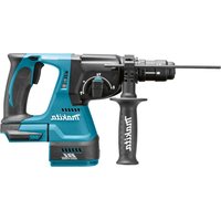
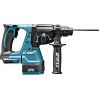
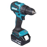
HP003G - Drill MAKITA - Free user manual and instructions
Find the device manual for free HP003G MAKITA in PDF.

User questions about HP003G MAKITA
0 question about this device. Answer the ones you know or ask your own.
Ask a new question about this device
Download the instructions for your Drill in PDF format for free! Find your manual HP003G - MAKITA and take your electronic device back in hand. On this page are published all the documents necessary for the use of your device. HP003G by MAKITA.
USER MANUAL HP003G MAKITA
natural_image
Line drawing of a mechanical power tool with drill bit and base mount (no text or symbols)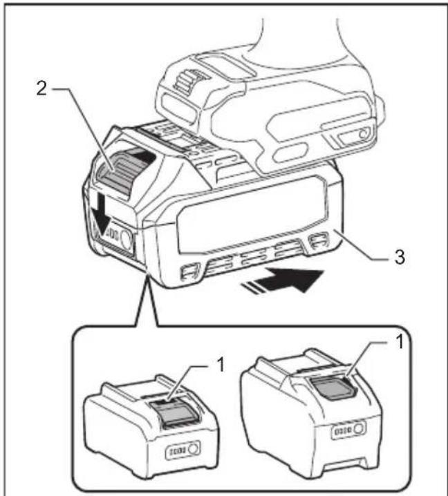
text_image
Technical diagram showing a device with labeled parts and two close-up views of the printer's internal structure.Fig.1
text_image
1 2 Fig.4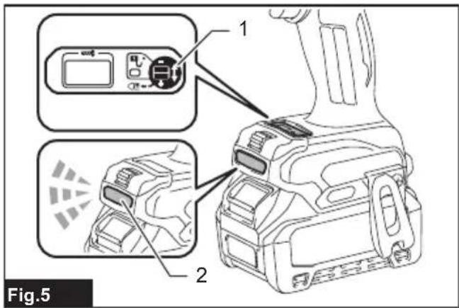
text_image
1 2 Fig.5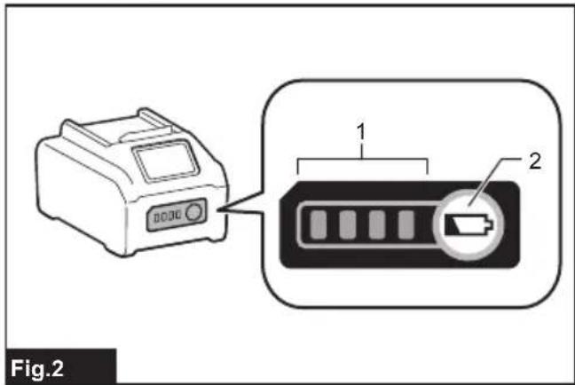
text_image
Fig.2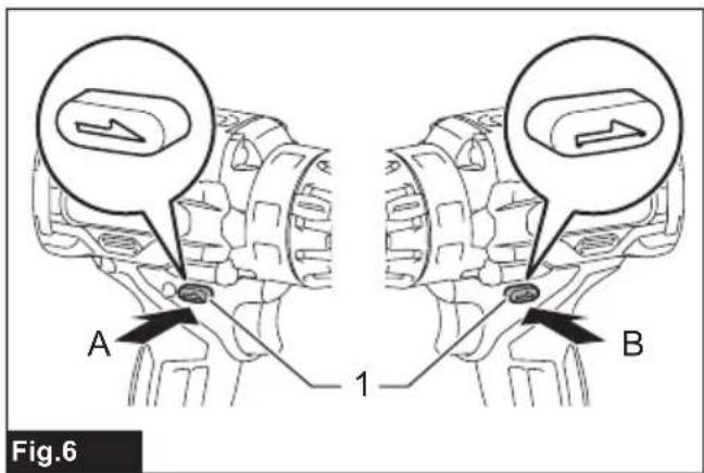
text_image
Fig.6 A 1 B
natural_image
Technical line drawing of a drill bit with labeled component (no text or symbols beyond label)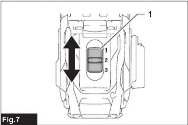
text_image
Fig.7 1 2 3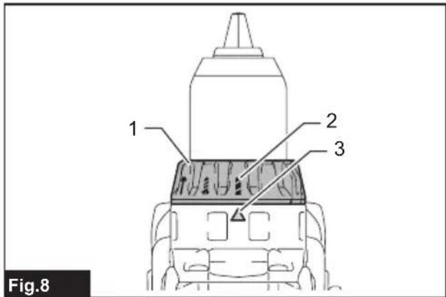
text_image
1 2 3 Fig.8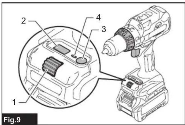
text_image
1 2 3 4 Fig.9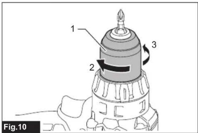
text_image
1 2 3 Fig.10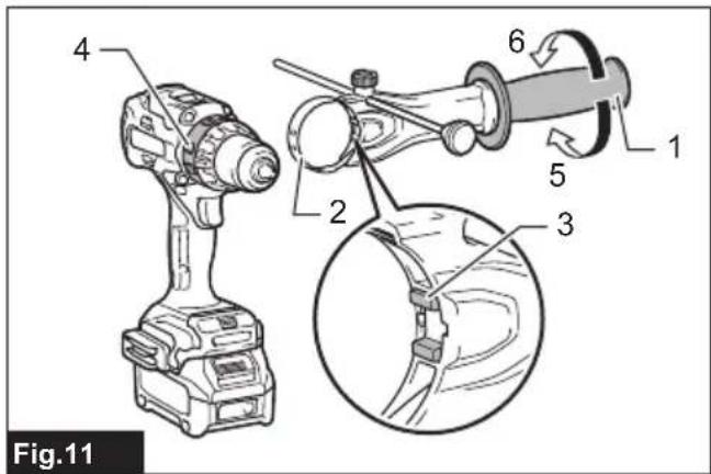
text_image
Fig.11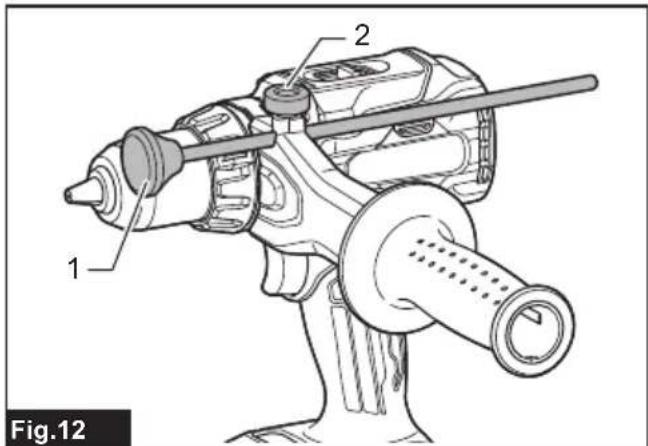
text_image
1 2 Fig.12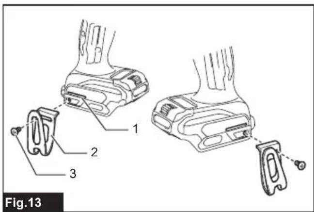
text_image
Fig.13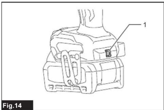
text_image
1 Fig.14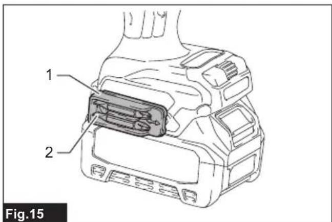
text_image
1 2 Fig.15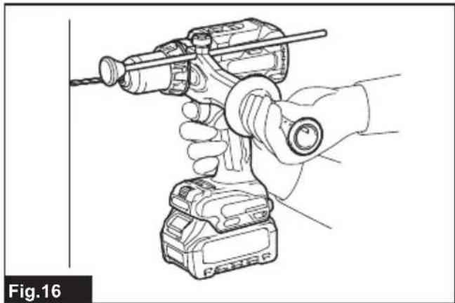
natural_image
Line drawing of a hand using a drill bit on a power supply unit (no text or symbols)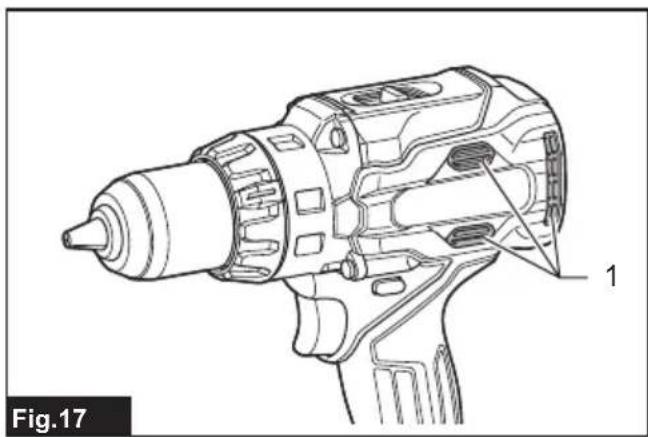
natural_image
Technical line drawing of a drill bit with labeled component 1 (no text or symbols beyond label)
text_image
Fig.18SPECIFICATIONS
| Model: HP003G | |||
| Drilling capacities Masonry 20 mm | |||
| Steel 20 mm | |||
| Wood Auger bit: 50 mm | Self-feed bit: 92 mmHole saw: 152 mm | ||
| Fastening capacities Wood screw | 10 mm x 90 mm | ||
| Machine screw M6 | |||
| No load speed (RPM) High (3) 0 | 2,400 min | -1 | |
| Medium (2) 0 - 1,800 min | -1 | ||
| Low (1) 0 - 650 min | -1 | ||
| Blows per minute High (3) 0 - 36,000 min | -1 | ||
| Medium (2) | 0 - 27,000 min^-1 | ||
| Low (1) | 0 - 9,750 min^-1 | ||
| Overall length | 197 mm | ||
| Rated voltage | D.C. 36 V - 40 V max | ||
| Net weight | 2.8 - 4.0 kg | ||
• Due to our continuing program of research and development, the specifications herein are subject to change without notice.
• Specifications may differ from country to country.
- The net weight value includes the lightest and heaviest combination of the attachment(s) for normal and safe use and battery cartridge(s) which are specified in the instruction manual.
Applicable battery cartridge and charger
| Battery cartridge | BL4020 / BL4025 / BL4040 / BL4040F* / BL4050F* / BL4080F*: Recommended battery |
| Charger | DC40RA / DC40RB / DC40RC / DC40WA / BCC01 / BCC02 |
• Some of the battery cartridges and chargers listed above may not be available depending on your region of residence.

WARNING: Only use the battery cartridges and chargers listed above. Use of any other battery cartridges and chargers may cause injury and/or fire.
Intended use
The tool is intended for impact drilling in brick, brickwork and masonry. It is also suitable for screw driving and drilling without impact in wood, metal, ceramic and plastic.
Noise
The typical A-weighted noise level determined according to EN62841-2-1:
Sound pressure level (L _pA ) : 88 dB (A)
Sound power level ( L_WA ): 96 dB (A)
Uncertainty (K) : 3 dB (A)
NOTE: The declared noise emission value(s) has been measured in accordance with a standard test method and may be used for comparing one tool with another.
NOTE: The declared noise emission value(s) can also be used in a preliminary assessment of exposure.
WARNING: Wear ear protection.
⚠ WARNING: The noise emission during actual use of the power tool can differ from the declared total value(s) depending on the ways in which the tool is used.
⚠ WARNING: Be sure to identify safety measures to protect the operator that are based on an estimation of exposure in the actual conditions of use (taking account of all parts of the operating cycle such as the times when the tool is switched off and when it is running idle in addition to the trigger time).
Vibration
The continuous vibration total value (tri-axial vector sum) determined according to EN62841-2-1:
Work mode: impact drilling into concrete
Vibration emission (ah, ID) : 6.8 m/s
Uncertainty (K) : 1.5 m/s²
Work mode: drilling into metal
Vibration emission (ah,D) : 2.5 m/s ^2 or less
Uncertainty (K) : 1.5 m/s ^2
NOTE: The declared vibration total value(s) has been measured in accordance with a standard test method and may be used for comparing one tool with another.
NOTE: The declared vibration total value(s) can also be used in a preliminary assessment of exposure.
WARNING: The vibration emission during actual use of the power tool can differ from the declared total value(s) depending on the ways in which the tool is used.
WARNING: Be sure to identify safety measures to protect the operator that are based on an estimation of exposure in the actual conditions of use (taking account of all parts of the operating cycle such as the times when the tool is switched off and when it is running idle in addition to the trigger time).
Declarations of Conformity
For European countries only
The Declarations of conformity are included in Annex A to this instruction manual.
SAFETY WARNINGS
General power tool safety warnings
⚠ WARNING Read all safety warnings, instructions, illustrations and specifications provided with this power tool. Failure to follow all instructions listed below may result in electric shock, fire and/or serious injury.
Save all warnings and instructions for future reference.
The term "power tool" in the warnings refers to your mains-operated (corded) power tool or battery-operated (cordless) power tool.
Cordless hammer driver drill safety warnings
Safety instructions for all operations
- Wear ear protectors when impact drilling. Exposure to noise can cause hearing loss.
- Use the auxiliary handle(s). Loss of control can cause personal injury.
- Hold the power tool by insulated gripping surfaces, when performing an operation where the cutting accessory or fasteners may contact hidden wiring. Cutting accessory or fasteners contacting a "live" wire may make exposed metal parts of the power tool "live" and could give the operator an electric shock.
- Always be sure you have a firm footing. Be sure no one is below when using the tool in high locations.
- Hold the tool firmly.
- Keep hands away from rotating parts.
- Do not leave the tool running. Operate the tool only when hand-held.
- Do not touch the drill bit or the workpiece immediately after operation; they may be extremely hot and could burn your skin.
- Some material contains chemicals which may be toxic. Take caution to prevent dust inhalation and skin contact. Follow material supplier safety data.
- If the drill bit cannot be loosened even you open the jaws, use pliers to pull it out. In such a case, pulling out the drill bit by hand may result in injury by its sharp edge.
- Make sure there are no electrical cables, water pipes, gas pipes etc. that could cause a hazard if damaged by use of the tool.
Safety instructions when using long drill bits
- Never operate at higher speed than the maximum speed rating of the drill bit. At higher speeds, the bit is likely to bend if allowed to rotate freely without contacting the workpiece, resulting in personal injury.
- Always start drilling at low speed and with the bit tip in contact with the workpiece. At higher speeds, the bit is likely to bend if allowed to rotate freely without contacting the workpiece, resulting in personal injury.
- Apply pressure only in direct line with the bit and do not apply excessive pressure. Bits can bend causing breakage or loss of control, resulting in personal injury.
SAVE THESE INSTRUCTIONS.
WARNING: DO NOT let comfort or familiarity with product (gained from repeated use) replace strict adherence to safety rules for the subject product. MISUSE or failure to follow the safety rules stated in this instruction manual may cause serious personal injury.
Important safety instructions for battery cartridge
- Before using battery cartridge, read all instructions and cautionary markings on (1) battery charger, (2) battery, and (3) product using battery.
- Do not disassemble or tamper with the battery cartridge. It may result in a fire, excessive heat, or explosion.
- If operating time has become excessively shorter, stop operating immediately. It may result in a risk of overheating, possible burns and even an explosion.
- If electrolyte gets into your eyes, rinse them out with clear water and seek medical attention right away. It may result in loss of your eyesight.
- Do not short the battery cartridge:
(1) Do not touch the terminals with any conductive material.
(2) Avoid storing battery cartridge in a container with other metal objects such as nails, coins, etc.
(3) Do not expose battery cartridge to water or rain.
A battery short can cause a large current flow, overheating, possible burns and even a breakdown. - Do not store and use the tool and battery cartridge in locations where the temperature may reach or exceed 50 °C (122 °F).
- Do not incinerate the battery cartridge even if it is severely damaged or is completely worn out. The battery cartridge can explode in a fire.
- Do not nail, cut, crush, throw, drop the battery cartridge, or hit against a hard object to the battery cartridge. Such conduct may result in a fire, excessive heat, or explosion.
- Do not use a damaged battery.
- The contained lithium-ion batteries are subject to the Dangerous Goods Legislation requirements.
For commercial transports e.g. by third parties, forwarding agents, special requirement on packaging and labeling must be observed.
For preparation of the item being shipped, consulting an expert for hazardous material is required. Please also observe possibly more detailed national regulations.
Tape or mask off open contacts and pack up the battery in such a manner that it cannot move around in the packaging. -
When disposing the battery cartridge, remove it from the tool and dispose of it in a safe place. Follow your local regulations relating to disposal of battery.
-
Use the batteries only with the products specified by Makita. Installing the batteries to non-compliant products may result in a fire, excessive heat, explosion, or leak of electrolyte.
-
If the tool is not used for a long period of time, the battery must be removed from the tool.
-
During and after use, the battery cartridge may take on heat which can cause burns or low temperature burns. Pay attention to the handling of hot battery cartridges.
-
Do not touch the terminal of the tool immediately after use as it may get hot enough to cause burns.
-
Do not allow chips, dust, or soil stuck into the terminals, holes, and grooves of the battery cartridge. It may cause heating, catching fire, burst and malfunction of the tool or battery cartridge, resulting in burns or personal injury.
-
Unless the tool supports the use near high-voltage electrical power lines, do not use the battery cartridge near high-voltage electrical power lines. It may result in a malfunction or breakdown of the tool or battery cartridge.
-
Keep the battery away from children.
SAVE THESE INSTRUCTIONS.
CAUTION: Only use genuine Makita batteries. Use of non-genuine Makita batteries, or batteries that have been altered, may result in the battery bursting causing fires, personal injury and damage. It will also void the Makita warranty for the Makita tool and charger.
NOTICE: Makita is not responsible for any accidents resulting from the use of non-genuine Makita batteries or batteries that have been modified. Genuine Makita batteries have been rigorously evaluated for compatibility with Makita tools and chargers, in line with applicable legislation and safety standards.
Tips for maintaining maximum battery life
- Charge the battery cartridge before completely discharged. Always stop tool operation and charge the battery cartridge when you notice less tool power.
- Never recharge a fully charged battery cartridge. Overcharging shortens the battery service life.
- Charge the battery cartridge with room temperature at 10 °C - 40 °C (50 °F - 104 °F). Let a hot battery cartridge cool down before charging it.
- When not using the battery cartridge, remove it from the tool or the charger.
- Charge the battery cartridge if you do not use it for a long period (more than six months).
FUNCTIONAL DESCRIPTION
⚠️CAUTION: Always be sure that the tool is switched off and the battery cartridge is removed before adjusting or checking function on the tool.
Installing or removing battery cartridge
⚠️CAUTION: Always switch off the tool before installing or removing of the battery cartridge.
⚠️CAUTION: Hold the tool and the battery cartridge firmly when installing or removing battery cartridge. Failure to hold the tool and the battery cartridge firmly may cause them to slip off your hands and result in damage to the tool and battery cartridge and a personal injury.
To install the battery cartridge, align the tongue on the battery cartridge with the groove in the housing and slip it into place. Insert it all the way until it locks in place with a little click. If you can see the red indicator as shown in the figure, it is not locked completely.
To remove the battery cartridge, slide it from the tool while sliding the button on the front of the cartridge. ▶ Fig.1: 1. Red indicator 2. Button 3. Battery cartridge
⚠️CAUTION: Always install the battery cartridge fully until the red indicator cannot be seen. If not, it may accidentally fall out of the tool, causing injury to you or someone around you.
⚠️CAUTION: Do not install the battery cartridge forcibly. If the cartridge does not slide in easily, it is not being inserted correctly.
Indicating the remaining battery capacity
Press the check button on the battery cartridge to indicate the remaining battery capacity. The indicator lamps light up for a few seconds.
▶ Fig.2: 1. Indicator lamps 2. Check button
| Indicator lamps Remaining | capacity | ||
| Lighted Off | Blinking | ||
| 75% to 100% | |||
| 50% to 75% | |||
| 25% to 50% | |||
| 0% to 25% | |||
| Charge the battery. | |||
| Indicator lamps Remaining | capacity | ||
| Lighted Off | Blinking | ||
| The battery may have malfunctioned. | |||
NOTE: Depending on the conditions of use and the ambient temperature, the indication may differ slightly from the actual capacity.
NOTE: The first (far left) indicator lamp will blink when the battery protection system works.
Tool / battery protection system
The tool is equipped with a tool/battery protection system. This system automatically cuts off power to the motor to extend tool and battery life. The tool will automatically stop during operation if the tool or battery is placed under one of the following conditions:
Overload protection
When the tool is operated in a manner that causes it to draw an abnormally high current, the tool stops automatically. In this situation, turn the tool off and stop the application that caused the tool to become overloaded. Then turn the tool on to restart.
Overheat protection
When the tool is overheated, the tool stops automatically and the lamp blinks. In this situation, let the tool/battery cool before turning the tool on again.
Overdischarge protection
When the battery capacity is not enough, the tool stops automatically. In this case, remove the battery from the tool and charge the battery.
Protections against other causes
The protection system is also designed for other causes that could damage the tool and allows the tool to stop automatically. Take all the following steps to clear the causes when the tool has been brought to a temporary halt or stop in operation.
- Turn the tool off, and then turn it on again to restart.
- Charge the battery(ies) or replace it/them with recharged battery(ies).
- Let the tool and battery(ies) cool down.
If no improvement can be found by restoring the protection system, then contact your local Makita Service Center.
Electric brake
This tool is equipped with an electric brake. If the tool consistently fails to quickly stop after the switch trigger is released, have the tool serviced at a Makita service center.
Switch action
⚠️CAUTION: Before installing the battery cartridge into the tool, always check to see that the switch trigger actuates properly and returns to the "OFF" position when released.
To start the tool, simply pull the switch trigger. Tool speed is increased by increasing pressure on the switch trigger. Release the switch trigger to stop.
▶ Fig.3: 1. Switch trigger
NOTE: The tool automatically stops if you keep pulling the switch trigger for about 6 minutes.
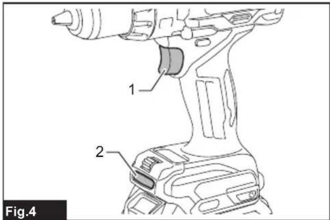
Lighting up the front lamp
⚠️CAUTION: Do not look into the light or look directly at the light source.
Pull the switch trigger to light up the front lamp. The front lamp keeps on lighting while the switch trigger is being pulled. The front lamp goes out approximately 10 seconds after releasing the switch trigger.
▶ Fig.4: 1. Switch trigger 2. Front lamp
Light mode
Long-press the button to activate light mode. In light mode, the front lamp remains lit for 1 hour. The front lamp automatically turns off after 1 hour. To turn the front lamp manually, press and hold the button
▶ Fig.5: 1. Button ☐ 2. Front lamp
NOTE: When the tool is overheated, the tool stops automatically and the front lamp starts flashing. In this case, release the switch trigger. The front lamp turns off in one minute.
NOTE: Use a dry cloth to wipe the dirt off the lens of the front lamp. Be careful not to scratch the lens of the front lamp, or it may lower the illumination.
NOTE: The front lamp is brighter in light mode than during normal operation.
Reversing switch action
⚠️CAUTION: Always check the direction of rotation before operation.
⚠️CAUTION: Use the reversing switch only after the tool comes to a complete stop. Changing the direction of rotation before the tool stops may damage the tool.
⚠CAUTION: When not operating the tool, always set the reversing switch lever to the neutral position.
This tool has a reversing switch to change the direction of rotation. Depress the reversing switch lever from the A side for clockwise rotation or from the B side for counterclockwise rotation.
When the reversing switch lever is in the neutral position, the switch trigger cannot be pulled.
▶ Fig.6: 1. Reversing switch lever
Speed change
CAUTION: Always set the speed change lever fully to the correct position. If you operate the tool with the speed change lever positioned in between "1" and "2" or "2" and "3", the tool may be damaged.
CAUTION: Do not use the speed change lever while the tool is running. The tool may be damaged.
This tool has a speed change lever. To change the speed, first switch off the tool and then slide the speed change lever to the "1" position for low speed, "2" position for medium speed or "3" position for high speed. Be sure that the speed change lever is set to the correct position before operation. Select the appropriate speed for your application.
If the tool speed decreases significantly during operation at high or medium speed, switch the speed change lever one speed lower and restart the operation.
| Displayed Number | Speed Torque Applicable operation |
| 1 Low High Heavy loading | operation |
| 2 Medium Medium Medium loading | operation |
| 3 High Low Light loading | operation |
▶ Fig.7: 1. Speed change lever
NOTE: If the speed change lever is difficult to slide, return the speed change lever to its previous position, briefly pull the switch trigger, and then slide the speed change lever again.
Selecting the action mode
NOTICE: Always set the ring correctly to your desired mode mark. If you operate the tool with the ring positioned halfway between the mode marks, the tool may be damaged.
NOTICE: Do not change the action mode while rotating.
This tool has three action modes.
• Drilling mode (rotation only)
• Hammer drilling mode (rotation with hammering)
• Screwdriving mode (rotation with clutch)
Select one mode suitable for your work. Turn the action mode changing ring and align the mark that you selected with the arrow on the tool body.
▶ Fig.8: 1. Action mode changing ring 2. Mark 3. Arrow
Adjusting the fastening torque

CAUTION: Make sure that the dial is clean. Depending on the work environment, foreign objects such as iron taps or chips may adhere to the dial and cause the personal injury.
The fastening torque can be adjusted in 41 levels in low speed, 30 levels in medium speed, and 25 levels in high speed.
- Align the marking with the arrow on the tool body by turning the action mode changing ring.
- Pull the switch trigger and release it (or push the button) to turn on the indicator.
- Push the button, and the green light blinks.
- Turn the dial, and adjust the torque level while the green light is blinking.
- Push the button to set the value.
▶ Fig.9: 1. Dial 2. Indicator 3. Button 4. Green light
To obtain a suitable torque level, perform a test drive with a workpiece of the same material that you are going to screw.
The following shows a rough guide of the relationship between the screw size and graduation.
Low speed
| Torque level | 1 | 2 | 3 | 4 | 5 | 6 | 7 | 8 | 9 | 10 | 11 | 12 | 13 | 14 | 15 | 16 | 17 | 18 | 19 | 20 | 21 | |
| Machine screw M4 M5 M6 | - | |||||||||||||||||||||
| Wood screw | Soft wood (e.g. pine) | 3.5 × 22 | 4.1 × 38 | - | 5.1 × 50 | - | 6.2 × 63 | - | ||||||||||||||
| Hard wood (e.g. lauan) | - | 3.5 × 22 | 4.1 × 38 | - | 5.1 × 50 | - | 6.2 × 63 | - | ||||||||||||||
| Torque level | 22 | 23 | 24 | 25 | 26 | 27 | 28 | 29 | 30 | 31 | 32 | 33 | 34 | 35 | 36 | 37 | 38 | 39 | 40 | 41 | |
| Machine screw | - | ||||||||||||||||||||
| Wood screw | Soft wood (e.g. pine) | - | 9 × 75 | - | 10 × 90 | - | |||||||||||||||
| Hard wood (e.g. lauan) | - | 9 × 75 | - | 10 × 90 | - | ||||||||||||||||
Medium speed
| Torque level | 1 | 2 | 3 | 4 | 5 | 6 | 7 | 8 | 9 | 10 | 11 | 12 | 13 | 14 | 15 | 16 | 17 | 18 | 19 | 20 | 21 | |
| Machine screw M4 M5 M6 | - | |||||||||||||||||||||
| Wood screw | Soft wood (e.g. pine) | 3.5 × 22 | 4.1 × 38 | - | 5.1 × 50 | - | 6.2 × 63 | - | ||||||||||||||
| Hard wood (e.g. lauan) | - | 3.5 × 22 | 4.1 × 38 | - | 5.1 × 50 | - | 6.2 × 63 | - | ||||||||||||||
| Torque level | 22 | 23 | 24 | 25 | 26 | 27 | 28 | 29 | 30 | |
| Machine screw | - | |||||||||
| Wood screw | Soft wood (e.g. pine) | - | ø9 × 75 | |||||||
| Hard wood (e.g. lauan) | - | |||||||||
High speed
| Torque level | 1 | 2 | 3 | 4 | 5 | 6 | 7 | 8 | 9 | 10 | 11 | 12 | 13 | 14 | 15 | 16 | 17 | 18 | 19 | 20 | 21 | |
| Machine screw M4 M5 M6 | - | |||||||||||||||||||||
| Wood screw | Soft wood (e.g. pine) | ø3.5 x 22 | ø4.1 x 38 | - | ø5.1 x 50 | - | ø6.2 x 63 | - | ||||||||||||||
| Hard wood (e.g. lauan) | - | ø3.5 x 22 | ø4.1 x 38 | - | ø5.1 x 50 | - | ø6.2 x 63 | - | ||||||||||||||
| Torque level | 22 | 23 | 24 | 25 | |
| Machine screw | - | ||||
| Wood screw | Soft wood (e.g. pine) | - | |||
| Hard wood (e.g. lauan) | - | ||||
NOTE: After pushing the button in step 5, the green light turns off. If you adjust the torque level again, start over from step 3.
NOTE: If you leave the green light blinking for a while, it stops blinking and the value displayed in the indicator will be set.
NOTE: You can set the fastening torque level in three patterns; high speed, medium speed, and low speed.
When the lever displays "1", the torque level in low speed can be set. When the lever displays "2", the torque level in medium speed can be set. When the lever displays "3", the torque level in high speed can be set.
When you change the speed with the speed change lever, the indicator blinks three times. After that, drive a trial screw to check the speed and torque level.
NOTE: If you pull the switch trigger while the green light is blinking, the green light turns off and you will not be able to adjust the torque level. To adjust the torque level again, release the switch trigger and turn the dial while the green light is blinking.
NOTE: If you turn the action mode changing ring while the green light is blinking, the green light turns off and you will not be able to adjust the torque level. To adjust the torque level again, start over from step 1.
Electronic function
The tool is equipped with the electronic functions for easy operation.
• Active Feedback sensing Technology If the tool is swung at the predetermined acceleration during operation, the motor is forcibly stopped to reduce the burden on the wrist.
NOTICE: Hold the tool firmly while operating.
NOTICE: If any malfunction occurred with the electronic function, the light blinks for 3 seconds, and then turns off. In that case, contact with Makita Authorized or Factory Service Centers to repair.
NOTE: This function does not work if the acceleration does not reach the predetermined one when the tool is swung.
NOTE: If the tool is forcibly stopped, release the switch trigger, and then pull the switch trigger to restart the tool.
ASSEMBLY
CAUTION: Always be sure that the tool is switched off and the battery cartridge is removed before carrying out any work on the tool.
Installing or removing driver bit/ drill bit
Optional accessory
Turn the sleeve counterclockwise to open the chuck jaws. Place the driver bit/drill bit in the chuck as far as it will go. Turn the sleeve clockwise to tighten the chuck. To remove the driver bit/drill bit, turn the sleeve counterclockwise.
▶ Fig.10: 1. Sleeve 2. Close 3. Open
Installing side grip (auxiliary handle)
Always use the side grip to ensure operating safety. Attach the side grip so that the protrusions on the grip base and steel band fit in the grooves on the tool barrel. Then tighten the grip by turning clockwise.
Depending on the operations, you can attach the side grip upward or right/left side of the tool.
▶ Fig.11: 1. Side grip 2. Steel band 3. Protrusion 4. Groove 5. Open 6. Close
Adjustable depth rod
The adjustable depth rod is used to drill holes of uniform depth. Loosen the clamp screw, set the depth rod to desired position, then tighten the clamp screw.
▶ Fig.12: 1. Depth rod 2. Clamp screw
Installing hook
WARNING: Use the hanging/mounting parts for their intended purposes only, e.g., hanging the tool on a tool belt between jobs or work intervals.
WARNING: Be careful not to overload the hook as too much force or irregular overburden may cause damage to the tool resulting in personal injury.
⚠️CAUTION: When installing the hook, always secure it with the screw firmly. If not secured firmly, the hook may come off from the tool and result in the personal injury.
⚠️CAUTION: Make sure to hang the tool securely before releasing your hold. Insufficient or unbalanced hooking may cause falling off and you may be injured.
The hook is convenient for temporarily hanging the tool. This can be installed on either side of the tool. To install the hook, insert it into a groove in the tool housing on either side and then secure it with a screw. To remove, loosen the screw and then take it out.
▶ Fig.13: 1. Groove 2. Hook 3. Screw
Using hole
WARNING: Never use the hanging hole for a purpose other than its intended purpose; for instance, tethering the tool at high location. Bearing stress in a heavily loaded hole may cause damage to the hole, resulting in injuries to you or people around or below you.
Use the hanging hole at the bottom rear of the tool to hang the tool on a wall using a hanging cord or similar strings.
▶ Fig.14: 1. Hanging hole
Installing driver bit holder
Optional accessory
Fit the driver bit holder into the protrusion at the tool foot on either right or left side and secure it with a screw. When not using the driver bit, keep it in the driver bit holders. Driver bits 45 mm-long (1-3/4") can be kept there.
▶ Fig.15: 1. Driver bit holder 2. Driver bit
OPERATION
CAUTION: Switch off the tool immediately if the tool malfunctions, foreign matter enters the tool, or abnormal noises are heard. Contact Makita service center or your local dealer to have the tool serviced or repaired.
Hold the tool firmly with one hand on the grip and the other hand on the handle to control the twisting action.
▶ Fig.16
NOTICE: When the speed slows down extremely, reduce the load or stop the tool to avoid the tool damage.
NOTICE: Do not cover vents, or it may cause overheating and damage to the tool.
▶ Fig.17: 1. Vent
Screwdriving operation
NOTICE: Adjust the dial to the proper torque level for your work.
NOTICE: Make sure that the driver bit is inserted straight in the screw head, or the screw and/or driver bit may be damaged.
First, turn the action mode changing ring so that the arrow on the tool body points to the ⚙ marking, and adjust the torque level.
Place the point of the driver bit in the screw head and apply pressure to the tool. Start the tool slowly and then increase the speed gradually. Release the switch trigger as soon as the tool stops the rotation automatically and the green light turns on for 5 seconds.
NOTE: When driving a wood screw, pre-drill a pilot hole 2/3 the diameter of the screw. It makes driving easier and prevents splitting of the workpiece.
NOTE: In a cold environment, the tool may stop at lower torque level depending on circumstances.
Hammer drilling operation
CAUTION: There is a tremendous and sudden twisting force exerted on the tool/drill bit at the time of hole breakthrough, when the hole becomes clogged with chips and particles, or when striking reinforcing rods embedded in the concrete.
First, turn the action mode changing ring so that the arrow on the tool body points to the marking. Be sure to use a tungsten-carbide tipped drill bit. Position the drill bit at the desired location for the hole, then pull the switch trigger. Do not force the tool. Light pressure gives best results. Keep the tool in position and prevent it from slipping away from the hole. Do not apply more pressure when the hole becomes clogged with chips or particles. Instead, run the tool at an idle, then remove the drill bit partially from the hole. By repeating this several times, the hole will be cleaned out and normal drilling may be resumed.
Blow-out bulb
Optional accessory
After drilling the hole, use the blow-out bulb to clean the dust out of the hole.
▶ Fig.18: 1. Blow-out bulb
Drilling operation
First, turn the action mode changing ring so that the arrow points to the marking. Then proceed as follows.
Drilling in wood
When drilling in wood, the best results are obtained with wood drills equipped with a guide screw. The guide screw makes drilling easier by pulling the drill bit into the workpiece.
Drilling in metal
To prevent the drill bit from slipping when starting a hole, make an indentation with a center-punch and hammer at the point to be drilled. Place the point of the drill bit in the indentation and start drilling.
Use a cutting lubricant when drilling metals. Some iron and brass which should be drilled dry are exceptions.
⚠️CAUTION: Pressing excessively on the tool will not speed up the drilling. In fact, this excessive pressure will only serve to damage the tip of your drill bit, decrease the tool performance and shorten the service life of the tool.
CAUTION: Hold the tool firmly and exert care when the drill bit begins to break through the workpiece. There is a tremendous force exerted on the tool/drill bit at the time of hole break through.
⚠️CAUTION: A stuck drill bit can be removed simply by setting the reversing switch to reverse rotation in order to back out. However, the tool may back out abruptly if you do not hold it firmly.
⚠️CAUTION: Always secure workpieces in a vise or similar hold-down device.
⚠️CAUTION: If the tool is operated continuously until the battery cartridge has discharged, allow the tool to rest for 15 minutes before proceeding with a fresh battery.
MAINTENANCE
⚠️CAUTION: Always be sure that the tool is switched off and the battery cartridge is removed before attempting to perform inspection or maintenance.
NOTICE: Never use gasoline, benzine, thinner, alcohol or the like. Discoloration, deformation or cracks may result.
To maintain product SAFETY and RELIABILITY, repairs, any other maintenance or adjustment should
be performed by Makita Authorized or Factory Service Centers, always using Makita replacement parts.
OPTIONAL ACCESSORIES
CAUTION: These accessories or attachments are recommended for use with your Makita tool specified in this manual. The use of any other accessories or attachments might present a risk of injury to persons. Only use an accessory or attachment for its stated purpose.
If you need any assistance for more details regarding these accessories, ask your local Makita Service Center.
- Drill bits
- Driver bits
• Tungsten-carbide tipped drill bit - Blow-out bulb
- Driver bit holder
- Hook
- Makita genuine battery and charger
NOTE: Some items in the list may be included in the tool package as standard accessories. They may differ from country to country.
SPÉCIFICATIONS
VEILIGHEIDSWAAR- SCHUWINGEN
▶ Fig.15: 1. Schroefbithouder 2. Schroefbit
BEDIENING
▶ Fig.17: 1. Ventilatieopening