
GWS 24230 BX Professional - Broyeur BOSCH - Free user manual and instructions
Find the device manual for free GWS 24230 BX Professional BOSCH in PDF.
Download the instructions for your Broyeur in PDF format for free! Find your manual GWS 24230 BX Professional - BOSCH and take your electronic device back in hand. On this page are published all the documents necessary for the use of your device. GWS 24230 BX Professional by BOSCH.
USER MANUAL GWS 24230 BX Professional BOSCH
- Not all of the accessories illustrated or described are included as standard delivery. Measured values determined according to EN 50 144. Typically the A-weighted noise levels of the ma- chine are: Sound pressure level: 93 dB (A); sound power level: 106 dB (A). Wear hearing protection! When using the standard auxiliary handle, the typically weighted maximum acceleration is
When using the vibration-dampening auxiliary handle, the hand-arm vibration at the auxiliary handle is typically below 2.5 m/s
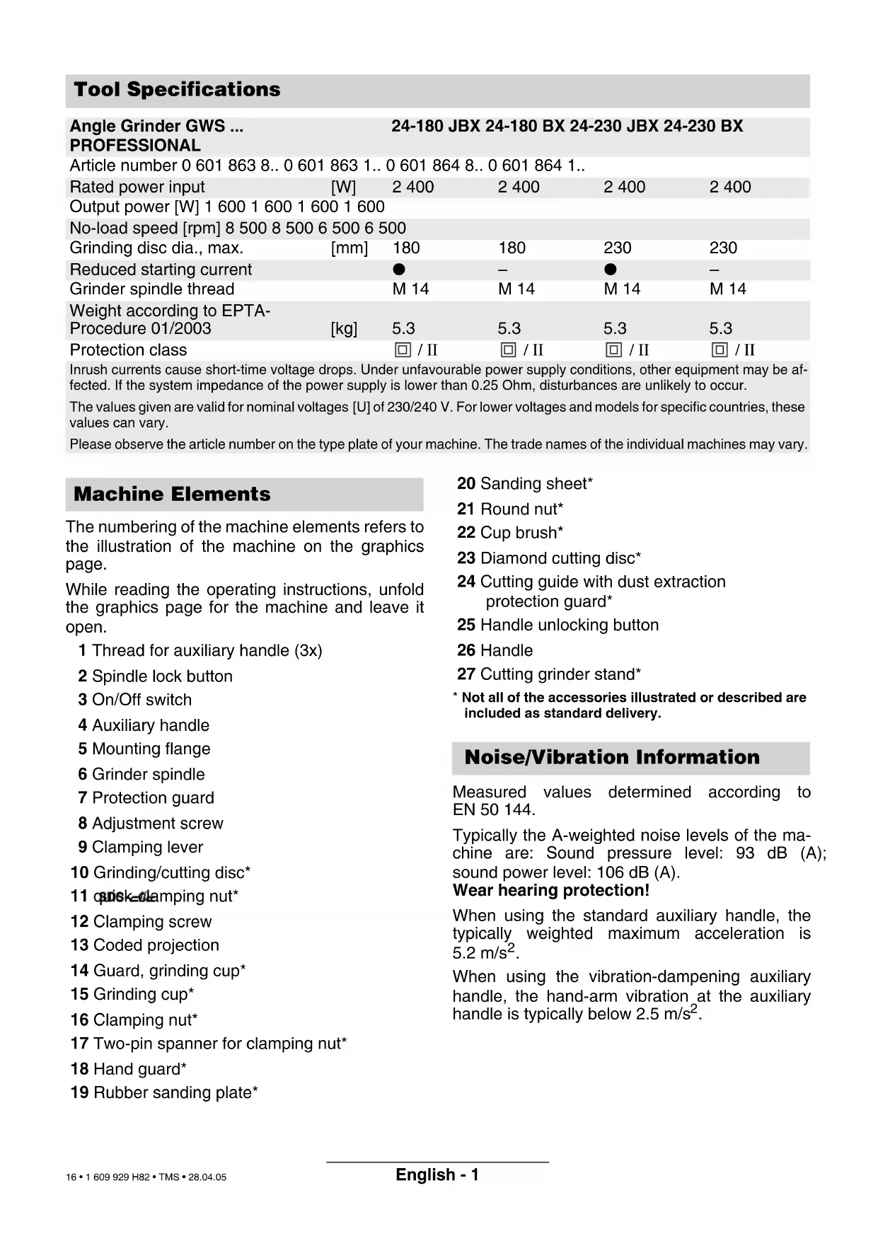
Tool Specifications Angle Grinder GWS ... PROFESSIONAL 24-180 JBX 24-180 BX 24-230 JBX 24-230 BX Article number 0 601 863 8.. 0 601 863 1.. 0 601 864 8.. 0 601 864 1.. Rated power input [W] 2 400 2 400 2 400 2 400 Output power [W] 1 600 1 600 1 600 1 600 No-load speed [rpm] 8 500 8 500 6 500 6 500 Grinding disc dia., max. [mm] 180 180 230 230 Reduced starting current ● – ● – Grinder spindle thread M 14 M 14 M 14 M 14 Weight according to EPTA- Procedure 01/2003 [kg] 5.3 5.3 5.3 5.3 Protection class / II / II / II / II Inrush currents cause short-time voltage drops. Under unfavourable power supply conditions, other equipment may be af- fected. If the system impedance of the power supply is lower than 0.25 Ohm, disturbances are unlikely to occur. The values given are valid for nominal voltages [U] of 230/240 V. For lower voltages and models for specific countries, these values can vary. Please observe the article number on the type plate of your machine. The trade names of the individual machines may vary. Machine Elements Noise/Vibration Information 1 609 929 H82.book Seite 1 Dienstag, 3. Mai 2005 3:11 15 16 • 1 609 929 H82 • TMS • 28.04.05English - 2 The machine is intended for cutting, roughing and brushing metal and stone materials without using water. For cutting stone, a cutting guide is re- quired. Slots in structural walls are subject to the Stand- ard DIN 1053, Part 1 or country-specific regula- tions. These regulations are to be observed under all circumstances. Before beginning work, consult the responsible structural engineer, architect or the construction supervisor. Read all instructions. Failure to fol- low all instructions listed below may result in electric shock, fire and/or se- rious injury. Additionally, the general safety instructions either in the enclosed booklet or those added in the centre of these operating instructions must be ob- served. SAVE THESE INSTRUCTIONS. Wear safety goggles. Wear hearing protection. ■ When working with the machine, always hold it firmly with both hands and provide for a secure stance. The power tool is guided more secure with both hands. ■ Secure the workpiece. A workpiece clamped with clamping devices or in a vice is held more securely than by hand. ■ Take protective measures when dust can develop during working that is harmful to one’s health, combustible or explosive. Ex- ample: Some dusts are regarded as carcino- genic. Work with dust/chip extraction and wear a dust mask. ■ Keep your workplace clean. Material mix- tures are particularly dangerous. Dust of light metal can be inflammable or explode. ■ Do not work materials containing asbes- tos. Asbestos is considered carcinogenic. ■ Do not use a machine with a damaged mains cable. Do not touch the damaged ca- ble and pull the mains plug when the cable is damaged while working. Damaged cables increase the risk of an electric shock. ■ Connect machines that are used in the open via a residual current device (RCD). Safety warnings that are common for grind- ing, sanding, wire brushing, polishing and abrasive cutting off operations: ■ This power tool is intended to function as a grinder, sander, wire brush, polisher or cut-off tool. Read all safety warnings, in- structions, illustrations and specifications provided with this power tool. Failure to fol- low all instructions listed below may result in electric shock, fire and/or serious injury. ■ Do not use accessories which are not spe- cifically designed and recommended by the tool manufacturer. Just because the ac- cessory can be attached to your power tool, it does not assure safe operation. ■ The rated speed of the accessory must be at least equal to the maximum speed marked on the power tool. Accessories run- ning faster than their rated speed can fly apart. ■ The outside diameter and the thickness of your accessory must be within the capacity rating of your power tool. Incorrectly sized accessories cannot be adequately guarded or controlled. ■ The arbour size of wheels, flanges, backing pads or any other accessory must properly fit the spindle of the power tool. Accessories with arbour holes that do not match the mount- ing hardware of the power tool will run out of balance, vibrate excessively and may cause loss of control. ■ Do not use a damaged accessory. Before each use inspect the accessory such as abrasive wheels for chips and cracks, backing pads for cracks, tear or excess wear, wire brushes for loose or cracked wires. If the power tool or accessory is dropped, inspect for damage or install an undamaged accessory. After inspecting and installing an accessory, position your- self and bystanders away from the plane of the rotating accessory and run the power tool at maximum no load speed for one minute. Damaged accessories will normally break apart during this test time. Intended Use Information on Structures For Your Safety 1 609 929 H82.book Seite 2 Dienstag, 3. Mai 2005 3:11 15 17 • 1 609 929 H82 • TMS • 28.04.05English - 3 ■ Wear personal protective equipment. De- pending on application, use face shield, safety goggles or safety glasses. As appro- priate, wear dust mask, hearing protectors, gloves and shop apron capable of stopping small abrasive or workpiece fragments. The eye protection must be capable of stop- ping flying debris generated by various opera- tions. The dust mask or respirator must be ca- pable of filtrating particles generated by your operation. Prolonged exposure to high inten- sity noise may cause hearing loss. ■ Keep bystanders a safe distance away from work area. Anyone entering the work area must wear personal protective equip- ment. Fragments of the workpiece or of a bro- ken accessory may fly away and cause injury beyond the immediate area of operation. ■ Hold the power tool only by the insulated gripping surfaces when performing an op- eration where the cutting tool may contact hidden wiring or its own power cord. Con- tact with a “live” wire will also make exposed metal parts of the power tool “live” and shock the operator. ■ Position the cord clear of the spinning ac- cessory. If you lose control, the cord may be cut or snagged and your hand or arm may be pulled into the spinning accessory. ■ Never lay the power tool down until the ac- cessory has come to a complete stop. The spinning accessory may grab the surface and pull the power tool out of your control. ■ Do not run the power tool while carrying it at your side. Accidental contact with the spin- ning accessory could snag your clothing, pull- ing the accessory into your body. ■ Regularly clean the power tool’s air vents. The motor’s fan will draw the dust inside the housing and excessive accumulation of pow- dered metal may cause electrical hazards. ■ Do not operate the power tool near flamma- ble materials. Sparks could ignite these mate- rials. ■ Do not use accessories that require liquid coolants. Using water or other liquid coolants may result in electrocution or shock. Kickback and related warnings ■ Kickback is a sudden reaction to a pinched or snagged rotating wheel, backing pad, brush or any other accessory. Pinching or snagging causes rapid stalling of the rotating accessory which in turn causes the uncontrolled power tool to be forced in the direction opposite of the accessory’s rotation at the point of the binding. For example, if an abrasive wheel is snagged or pinched by the workpiece, the edge of the wheel that is entering into the pinch point can dig into the surface of the material causing the wheel to climb out or kick out. The wheel may either jump toward or away from the operator, depending on the direction of the wheel’s movement at the point of pinching. Abrasive wheels may also break under these condi- tions. Kickback is the result of power tool misuse and/or incorrect operating procedures or con- ditions and can be avoided by taking proper precautions as given below. ■ Maintain a firm grip on the power tool and position your body and arm to allow you to resist kickback forces. Always use auxil- iary handle, if provided, for maximum con- trol over kickback or torque reaction during start-up. The operator can control torque re- actions or kickback forces, if proper precau- tions are taken. ■ Never place your hand near the rotating ac- cessory. The accessory may kickback over your hand. ■ Do not position your body in the area where power tool will move if kickback oc- curs. Kickback will propel the tool in the direc- tion opposite to the wheel’s movement at the point of snagging. ■ Use special care when working corners, sharp edges etc. Avoid bouncing and snag- ging the accessory. Corners, sharp edges or bouncing have a tendency to snag the rotating accessory and cause loss of control or kick- back. ■ Do not attach a saw chain woodcarving blade or toothed saw blade. Such blades create frequent kickback and loss of control. 1 609 929 H82.book Seite 3 Dienstag, 3. Mai 2005 3:11 15 18 • 1 609 929 H82 • TMS • 28.04.05English - 4 Safety warnings specific for grinding and abrasive cutting off operations ■ Always use the guard designed for the type of wheel you are using. The guard must be securely attached to the power tool and po- sitioned for maximum safety, so the least amount of wheel is exposed towards the operator. The guard helps to protect the oper- ator from broken wheel fragments and acci- dental contact with the wheel. ■ Use only wheel types that are recom- mended for your power tool and the spe- cific guard designed for the selected wheel. Wheels for which the power tool was not designed cannot be adequately guarded and are unsafe. ■ Wheels must be used only for recom- mended applications. For example: Do not grind with the side of a cut-off wheel. Abrasive cut-off wheels are intended for peripheral grinding; side forces applied to these wheels may cause them to shatter. ■ Always use undamaged wheel flanges that are of correct size and shape for your se- lected wheel. Proper wheel flanges support the wheel thus reducing the possibility of wheel breakage. Flanges for cut-off wheels may be different from grinding wheel flanges. ■ Do not use worn down wheels from larger power tools. A wheel intended for a larger power tool is not suitable for the higher speed of a smaller tool and may burst. Additional safety warnings specific for abra- sive cutting off operations ■ Do not “jam” the cut-off wheel or apply ex- cessive pressure. Do not attempt to make an excessive depth of cut. Overstressing the wheel increases the loading and susceptibility to twisting or binding of the wheel in the cut and the possibility of kickback or wheel break- age. ■ Do not position your body in line with and behind the rotating wheel. When the wheel, at the point of operation, is moving away from your body, the possible kickback may propel the spinning wheel and the power tool directly at you. ■ When the wheel is binding or when inter- rupting a cut for any reason, switch off the power tool and hold the power tool motion- less until the wheel comes to a complete stop. Never attempt to remove the cut-off wheel from the cut while the wheel is in mo- tion, otherwise kickback may occur. Inves- tigate and take corrective action to eliminate the cause of wheel binding. ■ Do not restart the cutting operation in the workpiece. Let the wheel reach full speed and carefully re-enter the cut. The wheel may bind, walk up or kickback if the power tool is restarted in the workpiece. ■ Support panels or any oversized workpiece to minimize the risk of wheel pinching and kickback. Large workpieces tend to sag under their own weight. Supports must be placed un- der the workpiece near the line of cut and near the edge of the workpiece on both sides of the wheel. ■ Use extra caution when making a “pocket cut” into existing walls or other blind areas. The protruding wheel may cut gas or water pipes, electrical wiring or objects that can cause kickback. Safety warnings specific for sanding opera- tions ■ When sanding, do not use excessively oversized sanding disc paper. Follow the manufacturers’ recommendations when selecting sanding paper. Larger sanding pa- per extending beyond the sanding pad presents a laceration hazard and may cause snagging, tearing of the disc, or kickback. Safety warnings specific for polishing opera- tions ■ Do not allow any loose portion of the pol- ishing bonnet or its attachment strings to spin freely. Tuck away or trim any loose at- tachment strings. Loose and spinning attach- ment strings can entangle your fingers or snag on the workpiece. 1 609 929 H82.book Seite 4 Dienstag, 3. Mai 2005 3:11 15 19 • 1 609 929 H82 • TMS • 28.04.05English - 5 Safety warnings specific for wire brushing operations ■ Be aware that wire bristles are thrown by the brush even during ordinary operation. Do not overstress the wires by applying ex- cessive load to the brush. The wire bristles can easily penetrate light clothing and/or skin. ■ If the use of a guard is recommended for wire brushing, do not allow any interfer- ence of the wire wheel or brush with the guard. Wire wheel or brush may expand in di- ameter due to work load and centrifugal forces. Additional safety instructions ■ Use suitable detectors to determine if util- ity lines are hidden in the work area or call the local utility company for assistance. Contact with electric lines can lead to fire and electric shock. Damaging a gas line can lead to explosion. Penetrating a water line causes property damage or may cause an electric shock. ■ If the power supply should be discon- nected, e. g. due to a power outage or pull- ing the mains plug, release the On/Off switch and set it to the Off position. This prevents uncontrolled restarting. ■ When working stone, use dust extraction. The vacuum cleaner must be approved for the extraction of stone dust. Using this equipment reduces dust-related hazards. ■ Use a cutting guide when cutting stone. Without sideward guidance, the cutting disc can jam and cause kickback. ■ Before any work on the machine itself, pull the mains plug. ■ For work with grinding or cutting discs, the pro- tection guard 7 must be mounted. Protection Guard with Locking Screw The coded projection 13 on the protection guard 7 ensures that only a guard that fits the machine type can be mounted. Loosen the clamping screw 12, if necessary. Place the protection guard 7 with coded projec- tion 13 into the coded groove on the spindle col- lar of the machine head and rotate to the required position (working position). The closed side of the protection guard 7 must always point to the operator. Tighten clamping screw 12. Always pay attention that the protection guard 7 is firmly seated on the spindle collar. Protection Guard with Quick Clamp Open the clamping lever 9. Place the protection guard 7 with coded projec- tion 13 into the coded groove on the spindle col- lar of the machine head and rotate to the required position (working position). The closed side of the protection guard 7 must always point to the operator. To fasten the protection guard 7, close the clamping lever 9. Always pay attention that the protection guard 7 is firmly seated on the spindle collar. The tightening tension of the clamping bracket can be changed by releasing or tightening the ad- justing screw 8. Mounting the Protective Devices 1 609 929 H82.book Seite 5 Dienstag, 3. Mai 2005 3:11 15 20 • 1 609 929 H82 • TMS • 28.04.05English - 6 Auxiliary Handle ■ For all work with the machine, the auxiliary handle must be mounted. Screw the auxiliary handle 4 into the head of the machine according to the working method. Vibration-dampening Auxiliary Handle The vibration-dampening auxiliary handle re- duces the vibrations, making operation more comfortable and secure. Do not make any alterations to the aux- iliary handle. Do not continue to use an auxiliary handle if it is damaged. Hand Guard For work with the rubber sanding plate 19 or with the cup brush 22/disc brush/flap disc, the hand guard 18 (accessory) is to be mounted. The hand guard 18 is fastened with the auxiliary handle 4. ■ Before any work on the machine itself, pull the mains plug. Grinding and cutting discs become very hot while working; do not touch until they have cooled. It is recommended to use the quick-clamping nut 11. When using the clamping nut 16 in- creased effort to loosen the clamping nut must be taken into account. Clean the grinder spindle and all parts to be mounted. For clamping and loosening the grind- ing tools, lock the grinder spindle 6 with the spin- dle lock button 2. Actuate the spindle lock button 2 only when the grinder spindle is at a standstill! Quick Clamping Nut When using the quick-clamping nut 11, grinding tools can be mounted without additional tools. Use only a flawless, undamaged quick-clamp- ing nut 11. When screwing on, take care that the side with printing does not point to the grinding disc. The arrow must point to the index mark 28. Lock the grinder spindle with the spin- dle lock button 2. Tighten the quick- clamping nut by firmly turning the grinding disc in clock- wise direction. A properly attached, undamaged quick- clamping nut can be loosened by hand when turning the knurled ring in anti- clockwise direction. Never loosen a tight quick-clamping nut with pliers. Always use the two-pin spanner. Insert the two-pin spanner as shown in the illustra- tion. Grinding/Cutting Disc Pay attention to the dimensions of the grind- ing disc. The mounting hole diameter must fit the mounting flange 5 without play. Do not use reducers or adapters. When using a diamond cutting disc, take care that the direction-of-rotation arrow on the dia- mond cutting disc and the direction of rotation of the machine (direction-of-rotation arrow on the machine head) agree. For mounting, see the illustration page. Position the grinding/cutting disc onto the mount- ing flange 5. Ensure that the grinding tool is seated centred and without play on the mounting flange. Screw on the quick-clamping nut 11 and tighten the grinding disc.
After mounting the grinding tool and be- fore switching on, check that the grind- ing tool is correctly mounted and that it can turn freely. Mounting the Grinding Tools
1 609 929 H82.book Seite 6 Dienstag, 3. Mai 2005 3:11 15 21 • 1 609 929 H82 • TMS • 28.04.05English - 7 Flap Disc For operations with the rubber sanding plate/the cup brush/the wheel brush /the flap disc, always mount the hand guard (acces- sory). Position the flap disc on the grinder spindle 6. Screw on the quick-clamping nut 11 and tighten the flap disc. Rubber Sanding Plate 19 For operations with the rubber sanding plate/the cup brush/the wheel brush /the flap disc, always mount the hand guard (acces- sory). For mounting, see the illustration page. Screw on the round nut 21 and tighten with the two-pin spanner. Increased effort must be taken into account when loosening the round nut 21. Cup Brush 22/Disc Brush For operations with the rubber sanding plate/the cup brush/the wheel brush /the flap disc, always mount the hand guard (acces- sory). The grinding tool must be able to be screwed onto the grinding spindle 6 until it rests firmly against the grinder spindle flange at the end of the grinder spindle threads. Tighten with an open-end spanner. Increased effort must be taken into account when loosening the grinding tool. Grinding Cup When working with grinding cups, use the special guard 14. The grinding cup 15 should always protrude from the guard 14 only as far as absolutely nec- essary for the work to be performed in each case. Adjust the guard 14 to this distance. For mounting, see the illustration page. Screw the clamping nut 16 on to the grinder spin- dle 6 ensuring that the flat side faces the grinding disc and tighten the clamping nut with the fitting offset two-pin spanner 17. Increased effort must be taken into account when loosening the clamping nut 16. All grinding tools mentioned in these operating in- structions can be used. The permissible speed [rpm] or the circumferen- tial speed [m/s] of the grinding tools used must at least match the values given in the table. Therefore, always observe the permissible rotational/circumferential speed on the label of the grinding tool. Observe correct mains voltage: The voltage of the power source must agree with the voltage specified on the nameplate of the machine. Equipment marked with 230 V can also be con- nected to 220 V. Switching On and Off To start the machine, press the On/Off switch 3 forward and then down. To lock-on, push the pressed On/Off switch 3 further forwards. To switch off the machine, release the On/Off switch 3 or push and release it then. Switch version without lock (country-specific): To start the machine, press the On/Off switch 3 forward and then down. To switch off the machine, release the On/Off switch 3. Approved Grinding Tools max. [mm] [mm] Db d[rpm] [m/s]
Test run! Check the grinding tool before use. The grinding tool must be properly mounted and rotate freely. Perform a test run of at least 30 seconds without load. Do not use damaged, out-of-round or vibrating grind- ing tools. Run-on Brake This machine is equipped with the Bosch Brake System, a patented electro-mechanical run-on brake. When switching off or in case of a power supply interruption, the grinding tool is stopped within a few seconds. This means the run-on time is re- duced by approx. 70 % in comparison to angle grinders without run-on brake, and that the ma- chine can be placed down in shorter time. Should the braking effect of the run-on brake no- ticeably diminish, have the machine checked by an after-sales service centre for Bosch power tools. Reduced Starting Current (GWS 24-180 JBX/GWS 24-230 JBX) As a result of soft starting, a 13 A fuse is ade- quate. A machine without reduced starting current requires higher fuse protection (use at least a 13 A time-delay fuse). ■ Exercise caution when cutting slots in structural walls: See Information on Struc- tures. ■ Clamp the workpiece if it does not remain sta- tionary due to its own weight. ■ Do not strain the machine so heavily that it comes to a standstill. ■ Grinding and cutting discs become very hot while working; do not touch until they have cooled. Rough Grinding The best roughing results are achieved when setting the machine at an angle of 30° to 40°. Move the machine back and forth with mod- erate pressure. In this manner, the workpiece will not become too hot, does not discolour and no grooves are formed. Never use a cutting disc for roughing. Flap Disc With the flap disc (accessory), curved surfaces and profiles (contour sanding) can be worked. Flap discs have a considerably higher service life than sanding sheets, lower noise level and lower sanding temperatures. Cutting When cutting, do not press, tilt or oscillate the machine. Work with moderate feed, adapted to the ma- terial being cut. Do not reduce the speed of running down cutting discs by applying sideward pressure. The direction in which the cutting is performed is impor- tant. The machine must always work in an up-grinding motion. Therefore, never move the machine in the other direction! Otherwise, the dan- ger exists of it being pushed uncon- trolled out of the cut. Operating Instructions 1 609 929 H82.book Seite 8 Dienstag, 3. Mai 2005 3:11 15 23 • 1 609 929 H82 • TMS • 28.04.05English - 9 Cut Off Grinder Stand With the cut off grinder stand 27 (accessory), workpieces can be cut at angles of 0 to 45° at the same lengths. The safety notes and operating instructions in the respective instruction manual of the cut off grinder stand are to be strictly observed. Use only original Bosch cut off grinder stands. Cutting Stone ■ The machine must be used only for dry cutting/ grinding. It is best to use a diamond cutting disc. As a safety measure against jamming, use the cutting guide 24 with the special dust extrac- tion protection guard. Operate the machine with dust extraction only. In addition, wear a dust mask. The vacuum cleaner must be approved for the extraction of ma- sonry dust. Bosch provides suit- able vacuum clean- ers. Switch on the ma- chine and place the front part of the cut- ting guide on the workpiece. Slide the machine with moderate feed, adapted to the material to be worked (Figure). For cutting especially hard material, e. g., con- crete with high pebble content, the diamond cut- ting disc can overheat and become damaged as a result. This is clearly indicated by circular sparking, rotating with the diamond cutting disc. In this case, interrupt the cutting process and al- low the diamond cutting disc to cool by running freely at no-load speed for a short time. Noticeable decreasing work progress and circu- lar sparking are indications of a diamond cutting disc that has become dull. Briefly cutting into abrasive material (e. g., lime-sand brick) can re- sharpen the disc. The handle 26 can be turned with respect to the motor housing by 90° either to the left or right. This allows for the On/Off switch to be positioned more conveniently for certain working situations, e. g., for cutting work with the cutting guide/ grinder stand (accessories) and for left-handers. Pull the handle unlocking button 25 firmly in the direction of the arrow ( ➊), turning the handle 26 at the same time to the desired position ( ➋) until it engages. The figure shows the handle 26 turned by 90°.
The handle unlocking button 25 and the On/Off switch 3 have a safety interlock. The machine cannot be switched on if the handle 26 is not engaged in one of the three possible positions. The handle 26 cannot be unlocked if the On/Off switch 3 is locked.