GE 365 - Mechanical chipper VIKING - Free user manual and instructions
Find the device manual for free GE 365 VIKING in PDF.
| Product type | Electric garden shredder |
| Brand | Viking |
| Model | GE 365 |
| Power supply | 400 V - 3~ / 3 kW / 4.8 A / 50 Hz |
| Max. rotation speed | 2800 rpm |
| Dimensions (L x W x H) | 66 x 52 x 135 cm |
| Weight | 33 kg |
| Guaranteed sound power level | 108 dB(A) |
| Reversible rotation direction | Yes, via direction reversal switch (soft waste / branches) |
| Safety devices | Engine stop if chute open, knife brake, restart lock |
| Cleaning | With a brush, do not use a high-pressure cleaner |
| Knife sharpening | Yes, with cooling and wear limit of 3 mm |
| Wear parts | Knives, knife disc |
| Optional accessory | 80 L collection bag (ref. 6903 760 2520) |
| Appliance protection | Protection class I, protection against water splashes |
Frequently Asked Questions - GE 365 VIKING
User questions about GE 365 VIKING
0 question about this device. Answer the ones you know or ask your own.
Ask a new question about this device
Download the instructions for your Mechanical chipper in PDF format for free! Find your manual GE 365 - VIKING and take your electronic device back in hand. On this page are published all the documents necessary for the use of your device. GE 365 by VIKING.
USER MANUAL GE 365 VIKING
natural_image
Exterior view of a VIKIN VIKIME 3D printer with wheels and top mount (no text or symbols on device body)
natural_image
Viking dust spreader with a cylindrical top and wheels (no visible text or symbols)DE Gebrauchsanleitung
EN Instruction manual
FR Manuel d'utilisation
NL Gebruiksaanwijzing
IT Istruzioni per l'uso
ES Manual de Instrucciones
PT Manual de utilização
NO Bruksanvisning
SV Bruksanvisning
Fl Käyttöohjeet
DA Betjeningsvejledning
HU Használati útmutató
EL Οδηγίες χρήσης
INT 1
www.viking-garden.comB


Inhaltsübersicht

Gerätebeschreibung

natural_image
Diagram of a screwdriver being inserted into a socket, showing the tool's rotation (no text or symbols present)Thank you for deciding to purchase a quality appliance from VIKING.
This appliance is manufactured using the most up-to-date production techniques and comprehensive quality assurance procedures. Our aim is to ensure that you are 100% satisfied.
If you have any queries about your appliance please direct them to your retailer or directly to our marketing company.
I hope you will be completely satisfied with your VIKING appliance
Signed

Nikolas Stihl
Managing Director
For your safety 2
Clothing and Configuration 2
Behaviour when Mulching 2
Maintenance and Repairs 3
Warning - Electrical Hazards 3
Description of symbols 4
Switch for changing rotational direction of the cutting assembly 5
Appliance description 5
Supplied items 6
Open tool compartment 7
Assembly 7
Assemble Basic Appliance 7
Assemble Funnel 7
Assemble locking screw 7
Mount Tube 7
Commissioning 8
Electrically Connect Appliance 8
Reverse phase plug 8
Correct Rotational Direction 8
Notes on mulching 8
From the home and kitchen 8
From the garden 8
What does not belong to the mulcher? 8
Switching off 9
Correct loading of the motor 9
Maintenance 9
Cleaning 9
Blade sharpening 10
Storage 10
Design of the cutting assembly Multicut 300 10
Assembly - Disassembly of the cutting assembly 10
Technical data 11
Electro-mechanical Safety Equipment 11
Notes on maintenance and care 12
CE - Producer's declaration of conformity 13
Accessories 14
VIKING constantly strives to improve all of its machines and appliances. As such we must reserve the right to make changes to the type, technology, and equipment of the delivered items.
We are therefore unable to consider claims based on the information or illustrations in this document.
For your safety

The accident prevention regulations are to be observed when working with the garden mulcher.

Read the whole instruction manual before using for the first time and keep in a safe place for future reference. Familiarise yourself
thoroughly with the appliance.
Viking mulchers are designed for private use and are suitable for the reduction of organic kitchen refuse as well as plant refuse.
The garden mulcher must not be used for materials or tasks other than those described in these service instructions.
This appliance may only be used in the configuration in which it is delivered or in one which is expressly permitted by VIKING. In addition no changes may be made which could lead to an increased likelihood of accident.
- The user should be acquainted with the proper use of the appliance by either the vendor or some other competent person.
• The appliance should not be operated after the consumption of alcohol, medications which impair reactions, or drugs -
The user is responsible for the prevention of injury or damage to third parties while operating the mulcher. Never work while third parties, especially children, or animals are nearby. Juveniles under 16 years of age are not permitted to operate the mulcher.
-
The Garden mulcher should only be passed on (lent) to persons who are familiar with the proper use of this appliance. The owner's manual should always accompany the mulcher.
- Please observe the regulations regarding permitted operation times for motor-driven gardening tools.
Clothing and configuration
- The user should wear suitable clothing when using the garden mulcher. This consists of close fitting working clothes, robust gloves and shoes fitted with non-slip soles.
Safety goggles must always be used and ear protectors should be worn when mulching wood.


Behaviour when mulching
- The appliance is to be thoroughly inspected each time before it is commissioned to ensure that it is sealed in accordance with regulations. The appliance must be securely erected on ground which is level and stable. Only work in good lighting conditions. Assume a secure stance, and work in a quiet and considerate manner. Use the machine prudently to prevent the possibility of harming others.
- Never stand in front of the ejector either when the motor is switched on or when working. There must be no mulched material in the mulcher when it is switched on.
- Do not operate the machine on a paved or gravel surface where ejected material could cause injury.
- Never put your face over the filling hopper or in front of the ejector and never place your hand in the filling hopper or the ejector slot while the appliance is running. There is a serious risk of injury to eyes, face and hands.
- Do not allow hands or any other part of the body or clothing inside the feeding funnel, discharge chute, or near any moving part.
- The cutting tools must be regularly checked for secure seating and damage. Ensure that all bolts are constantly tightened.
- When filling the mulcher take great care to ensure that no foreign objects like metal fragments, stones, plastic, etc. enter the mulch chamber, as this can lead to damage, and back-firing through the filling hopper. Blockages must be cleared for the same reason.
-
Do not allow processed material to build up in the discharge zone: this may prevent proper discharge and can result in a kickback of material through the feed intake opening.
-
Switch off the motor and disconnect the electrical supply before leaving the appliance unattended.
- Only attach or detach the mulcher container with the motor switched off. Never use a garden mulcher with damaged safety appliances.
- The safety appliances installed by the manufacturer must not be removed or circumvented. All moving parts must come to a complete standstill:
- before clearing obstructions or blockages in the ejector channel,
- before inspecting, cleaning, or working on the mulcher or opening the tube,
- before leaving the mulcher unattended.
- before the machine is transported.
- If the mulcher starts making unusual noises or severe vibrations, the machine must be inspected immediately
- Note that the cutting tool will run on for a few seconds after the motor is switched off.
- Avoid switching the appliance on repeatedly within a short period of time, particularly by "playing" with the on/off switch.
- Owing to the voltage fluctuations caused by this appliance during the run-up period, other devices connected to the same circuit may be subject to interference in the case of unsuitable power supply conditions.
In this case, appropriate steps should be taken (e.g. connection to a different circuit than the one used by the affected device, or operation of the appliance using a circuit with a lower impedance).
Maintenance and repairs
Remove the plug from the power socket before all work on the appliance.
Only perform the maintenance which are described in the Owner's Manual. All other procedures should be carried out by a specialist dealer.
VIKING recommends that you have maintenance operations and repairs performed exclusively by a VIKING specialist dealer.
VIKING recommends the use of original VIKING tools, accessories and spare parts. Their properties are optimally adapted to the appliance and the user's requirements. When replacing the cutting tool, make sure you install the correct type of cutting tool. The electrical connection lead may only be repaired or re-newed by an approved electrician.
- If components or protective devices are removed as a result of maintenance work, they must be immediately re-fitted (as per the regulations). To avoid injury, protective gloves must be worn when working on the cutting assembly.
- Re-new safety and warning notices on the appliance if they become illegible. Your VIKING supplier stocks replacement stickers.
Warning – electrical hazards
- The power supply wiring, the power supply socket, the on/off switch and the connection lead are critically important items for electrical safety. To avoid exposure to the danger of electrical shock; damaged cable, couplings, and plugs or connection leads prohibited by the regulations must not be used.
- Keep the power source clean of debris and other accumulations to prevent damage to the power source or possible fire.
- For the above reason, regularly inspect the connection lead for signs of damage or ageing (brittleness).
- When working outside, only use extension cables which are protected against the ingress of moisture (see chapter: Commissioning)
- Although the drive motor is splash proof, the garden mulcher must not be used in the rain or in wet conditions.
- Do not leave the appliance unprotected in the rain.
- Disconnect the electrical power supply by removing the plug from the power socket, do not simply tug on the connection lead.
- When operating the mulcher in the open, the power socket should be fitted with a residual current breaker (r.c.b), or should be connected to an adapter with a similar appliance (obligatory in Switzerland). More precise information can be obtained from your electrician.
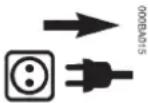
Discription of symbols

215ba001
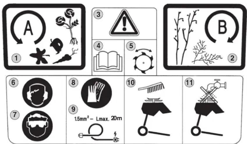
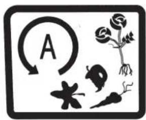
- Anti-clockwise rotation (All types of plant refuse)
- Clockwise rotation (bushes, branches)
- Caution!
- Caution! Before commissioning, read owner's manual.
- Caution! Rotating tool.
- Wear ear protection.
- Wear protective goggles.
- Wear protective gloves.
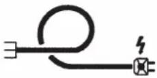
- The maximum permitted length of 1.5 mm ^2 cross sectional area cable is 20 m.
- Clean the appliance using a brush.
- The appliance must not be cleaned using a water jet, or pressure hose.
- Before performing any work on the cutting tool, before carrying out maintenance and cleaning work, before checking whether the connection lead is entwined or damaged, or before leaving the mower unattended, switch off the motor and disconnect the plug.
- Keep other people away from the dangerous area.
Switch for changing rotational direction of the cutting assembly
Switch Positions
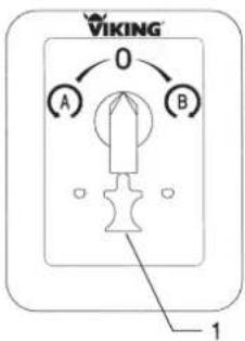

Switch lever: left; A
Anti-clockwise rotating blade for all types of plant refuse.
Switch lever: right; B
Clockwise rotation of blade for bushes and branches.
Be careful: Do not feed in material containing earth or stones as this will prematurely blunt the cutting blades (see: Note on mulching).

Switch lever: centre
Motor stops within a few seconds.
Switch inhibitor (1)
Prohibits the immediate reversal of rotational direction.
NOTE: Allow the motor to come to a complete standstill before reversing the rotational direction.
Check the rotational direction for the GE365 model! (see: reverse phase plug)
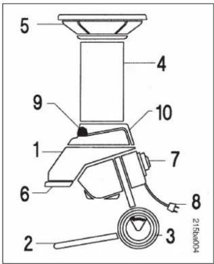
Appliance description
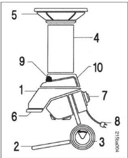
1 Basic appliance
2 Support foot
3 Wheels
4 Tube
5 Funnel
6 Ejector
7 Reversal switch
8 Power supply connection
9 Cover bolts
10 Cutter blades
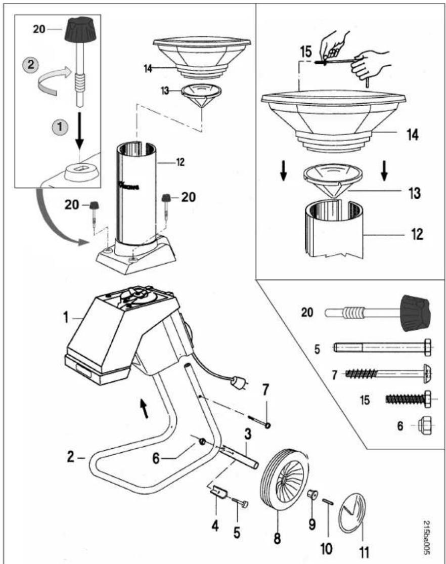
Supplied items
| Pos. | Description | |
| 1 Basic appliance 12 Wheel foot 13 Wheel axle 14 Limit stop 25 Bolt M6x60 26 Nut M6 27 Bolt K50x50 28 Wheel 29 Plug 210 Pin 211 Wheel cap 212 Tube13 Funnel rubber seal14 Funnel15 One way bolt K60x1816 Screwdriver17 Combination spanner18 Assembly tool19 Torx-spanner20 Locking screw | ||
| 11113 | ||
| 3 | ||
| 1 | ||
| 1 | ||
| 1 | ||
| 2 | ||
Open tool compartment
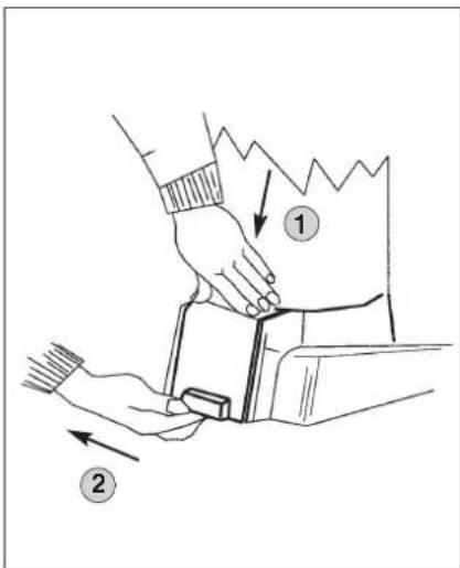
The tools which are required for assembly are in the tool compartment.
To open the tool compartment:
① Press the lid down a little with one hand.
② Pull the lid off with the other hand.
Assembly
Assemble basic appliance
Mount the basic appliance 1 on the support foot 2 and use the Torx-spanner 19 to firstly lightly tighten the bolts 7.
Then mount the wheel axle 3 and the limit stop 4 on the support foot 2 using the bolts 5 and the nuts 6 (combination spanner 17).
Now insert the wheels 8 and the plugs 9 on the wheel axle 13. Fix the plugs 9 by hammering in the pins 10.
Next press both of the wheel caps 11 on the wheels 8 and place the appliance on an even floor.
Subsequently tighten the bolts 7. (Torx-spanner 19)
Assemble funnel
Mount the funnel rubber seal 13 and the funnel 14 on the tube 12 and fasten these parts with the one-way bolts 15 using the screwdriver 16.
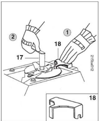
Assemble locking screw
① Insert locking screw 20 in slot.
② Fully screw in locking screw 20 while applying pressure.
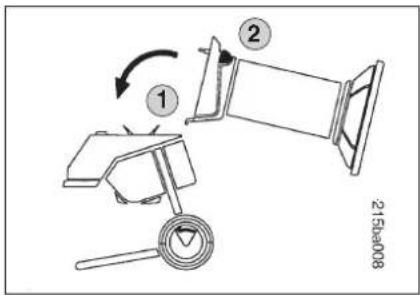
Mount tube
① Suspend and then mount the tube 12 on the hinge in the basic appliance 1.
② Tighten both cover bolts simultaneously.
Commissioning
3 × 1.5 ~mm^2- Lmax. 20 ~m
Electically connect appliance.
The power supply connection lead must be protected with either a 10 or 16 ampere fuse (see Tech. Data).
Only cables which are not lighter than rubber insulated cables H07 RN-F DIN/VDE 0282 and which have a minimum cross sectional area of
1.5 mm ^2 for less than 20 m or 2.5 mm ^2 for greater than 20 m may be used as connection cables.
The coupling of the cable connection must be made from rubber or must be sheathed in rubber and in accordance with the standard DIN/VDE 0620. Alternating current models must use a 16 A CEE plug appliance and a 5 pole cable. The plug appliance must be splash proof.
Use of unsuitable extension cables causes power loss and can cause damage to the motor (refer to the chapter: "For Your Safety")
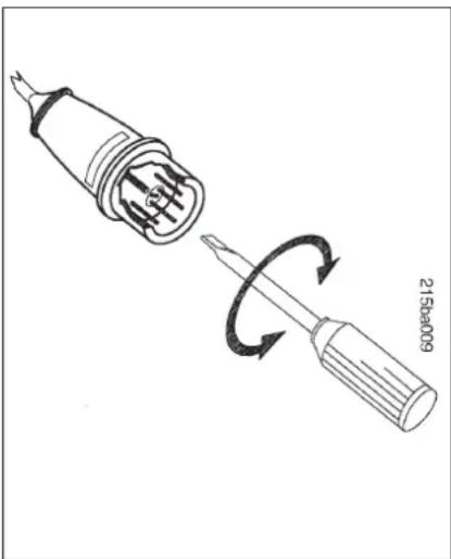
Reverse phase plug
natural_image
Diagram of a screwdriver being inserted into a socket, showing the tool's rotation (no text or symbols present)Correct rotational direction
With the switch in position A the cutting assembly of this mulcher rotates anticlockwise when observed from above through the gutter of the cutting assembly.
Check the rotational direction of the alternating current model GE365. If the rotational direction is incorrect, reverse the motor poles using the reverse phase plug. (see above illus.)
Notes on mulching
What can be mulched?
From the home and kitchen
Fruit, vegetable waste, newspaper, packaging paper, corrugated cardboard, wood wool, decayed wood, thin wooden fruit boxes (without nails). Soften paper and cardboard in water before mulching.
From the garden
Tree and hedge cuttings, fruit canes, rose pruning, withered flowers (autumn clear out), vegetable refuse, leaves, potato vines, tomato plants, bean stalks, pea straws, grass cuttings, hay, straw, foliage, bushes, etc.
What does not belong in the mulcher?
Stone, glass, metal fragments, plastic, chemical cleaners, printed paper, (magazines and brochures), thick wood and hard wood. The rule of thumb is: If you wouldn't put it on the compost heap, don't put it in the mulcher.
Tree and hedge cuttings should be processed immediately while they are fresh, as the mulcher can then shred them more efficiently than when they are old.
Maintenance
Switching off
Only switch the motor off when the mulcher is completely empty. Other-wise the blades can become jammed when the appliance is re-started.
Correct loading of the motor
The garden mulcher may only be loaded so that the motor speed is not greatly reduced. If an overload should occur, the incorporated thermal overload switch will switch the motor off automatically.
Important: To avoid overheating the motor, the motor should be allowed to cool off for approx. 10 mins before it is re-started. If the mulcher is jammed, switch the motor off immediately and disconnect the electrical power supply. Then investigate and eliminate the cause of the breakdown. If the thermal overload switch trips repeatedly, the following causes could be present:
- unsuitable connecting lead (see: electrical power connection),
- circuit overload,
- appliance overload due to excessive material feed rate or blunt blades.
Cleaning
Clean the appliance thoroughly after use. Use the appliance sympathetically to avoid breakdowns and to prolong its lifetime. Use a commercially available product to protect the mulching tools and the mulch container (i.e. rapeseed oil) against corrosion.
The electric motors are splash proof and have a labyrinth seal with an additional seal ring on the tool shaft (see illus.). This should be regularly inspected (i.e. during blade sharpening).
Only use a brush to clean the appliance.
Never use a water jet or high pressure hose on motor components, seals, bearings, and electrical components (i.e. switches). It could result in expensive repairs!
The electric motors require no maintenance.
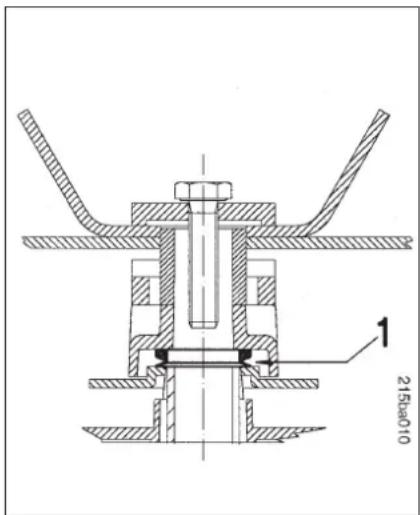
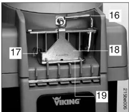
Motor seal with labyrinth seal and seal ring (1).
The seal ring is accessible after the cutting assembly and the blade mounting have been removed.
Important: The power supply must be disconnected before any maintenance or operation is performed on the mulching tools. Never touch any part of the cutting assembly while it is in motion, wait until it is at a complete standstill.
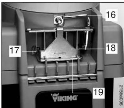
Design of cutting assembly Multicut 300
Assembly - Disassembly of the cutting assembly
Sharpening Cutting Assembly
If the cutting quality deteriorates slowly over time, the blades have probably been blunted.
When re-sharpening the cutting assembly the following points are to be observed:
• Cool the blades during sharpening (i.e. with water). The blades must not become blue, or they will become less resistant to wear.
- Sharpen the blade evenly, to avoid vibrations resulting from imbalance.
- Inspect the blades for damage before installation: They must be re-newed if notches or cracks are visible, or if the cutting edge has already been ground back 3 mm (grinding limit).
Storage
The storage room should be dry, free from dust, and inaccessible to children. If the appliance is defective, repair it prior to storage so that it is always in a condition that is safe to use.
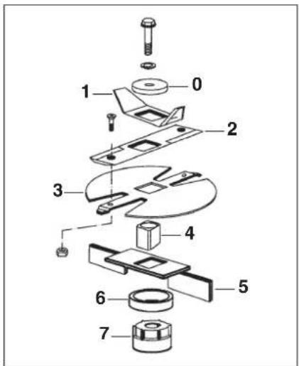
The components of the blade assembly must be offset at 90° to one another (see illus.).
0 Clamping disc
1 Pre-mulcher
2 Combination blade
3 Multi-cut-disc
4 Square end
5 Ejector
6 Space pipe
7 Seal ring cover
VIKING recommends the use of original VIKING tools, accessories and spare parts. Their properties are optimally adapted to the appliance and the user's requirements.
• The installation must follow the illustrated procedure.
- Tighten all bolts!

Important:
Danger of injury!
Always wear gloves when working.
Technical data
- Directly driven by electric motor.
- Sealing of the mulch container from the motor using labyrinth and additional seal ring.
- Removable tube. Fastened with hinge and 2 cover bolts.
Electro-mechanical safety equipment
Both series have the following safety appliances fitted for your personal safety:
Motor stop. The motor can only be started when the tube is correctly locked in position. If it is open, the appliance switches off automatically.
Motor run-on brake. Reduces the run-on period between switching off and blade standstill to a few seconds.
Motor start up inhibitor. The appliance can only be started using the switch and not simply by plugging the connection lead into the power socket.
Electrical specifications
GE 345 GE 365
Supply voltage 230 V \~ 400 V - 3\~
Power consumption 2.2 kW 3 kW
Current consumption 10 A 4.8 A
Fusing min. (GB / AUS / NZ) 13 / 11 / 11 A anti-surge 10 A anti-surge
Frequency 50 Hz 50 Hz
Protective category Method of protection I Splash proofed I Splash proofed
Special feature Change of rotational direction using reversal switch
In accordance with Guideline 2000/14/EU:
Guaranteed sound power level L_WA
108 dB 108 dB
In accordance with EN 13683:
Sound pressure level at workplace L_pA
101 dB 101 dB
Dimensions and weight
Dimensions L/B/H cm 66/52/135 66/52/135
Weight in kg 31 33
Tighten Torque
Cutting Assembly 50 Nm 50 Nm
Notes on maintenance and care
Important information on maintenance and care of the product group
Electric garden shredders
Please always observe the following important information for the prevention of damage or excessive wear to your VIKING appliance:
1. Wearing parts
Some parts of the VIKING appliance are subject to normal wear even when used properly and must be replaced in due time depending on type and duration of use.
These include:
- Blades
- Blade disc
2. Observance of the information in this instruction manual
The VIKING appliance must be used, maintained and stored with the care described in this instruction manual. Any damage caused by non-observance of the safety, operating and maintenance instructions are the sole responsibility of the user.
This applies in particular to:
- power lead with inadequate dimensions (cross section)
- incorrect electrical connection (voltage)
- product modifications not approved by VIKING
- the use of tools or accessories which are not approved or suitable for the appliance, or are of inferior quality.
- improper use of the product
- use of the product for sporting or competitive events
- resultant damage due to continued use of the product with defective components
3. Maintenance operations
All work listed in the section
“Maintenance” must be performed regularly. If these maintenance operations cannot be carried out by the user himself, a specialist dealer must be commissioned to do it.
VIKING recommends that you have maintenance operations and repairs performed exclusively by a VIKING specialist dealer.
VIKING specialist dealers regularly attend training courses and are provided with technical information.
If these operations are neglected, faults may arise which are the responsibility of the user.
These include:
- damage to the drive motor as a result of inadequate cleaning of the cooling air guide (inlet slots)
- corrosive and other resultant damage caused by incorrect storage
- damage to the appliance through the use of inferior-quality spare parts.
- damage due to untimely or inadequate maintenance or damage due to maintenance or repair work not performed in the workshops of specialist dealers.
CE - Producer's declaration of conformity
We,
VIKING GmbH
declare, that the machine
Shredding machine for plant trimmings with electric motor
Manufacturer's brand: VIKING
Type: GE 345
GE 365
Productionidentification: 6000
conforms to the following EC guidelines:
98/37/EC, 2000/14/EC, 2002/95/EC,
2002/96/EC, 2004/108/EC, 2006/95/EC
The product has been developed and manufactured in conformance with the following standards:
EN 13683
EN 60335
Applicable conformity assessment procedure:
Appendix V (2000/14/EC)
Storage of technical documentation:
VIKING GmbH
Product approval
Measured sound power level: 107 dB(A)
Guaranteed sound power level:
108 dB(A)
The year of manufacture appears on the identification plate of the product.
Langkampfen, 02. 01. 2008
VIKING GmbH

Weiglhofer
Development Manager
Accessories
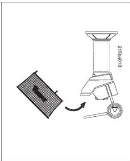
Mulch Container
Part No.: 6903 760 2520
(not included, available as an optional Accessory)
A very useful supplementary fitting is available upon request, which is hung directly on the mulcher ejector. The filled mulch container is convenient to carry and empty.
Capacity: 80 Litres
Environmental protection

The appliance, its packaging and accessories are all produced from recyclable
materials and must be disposed of accordingly.
By disposing of materials separately, and in an environmentally-friendly manner, valuable resources can be reused.
Sommaire
Chère cliente, cher client,
natural_image
Symbolic illustration of a circular arrow labeled 'A' pointing to a plant and flower, with other plants and leaves below (no text or labels)

natural_image
Diagram of a screwdriver being inserted into a socket, showing the tool's rotation (no text or symbols present)Sens de rotation correct
215ba001
natural_image
Diagram of a screwdriver being inserted into a socket, showing the tool's rotation (no text or symbols present)21564001
natural_image
Diagram of a screwdriver being inserted into a socket, showing the tool's rotation (no text or symbols present)2002/96/EC, 2004/108/EC, 2006/95/EC

Colocar la Tolva
natural_image
Diagram of a screwdriver being inserted into a socket, showing the tool's rotation (no text or symbols present)
natural_image
Diagram of a screwdriver being inserted into a socket, showing the tool's rotation (no text or symbols present)21824001

| Pos. | Betegnelse stk. | |
| 1 | Hovedenhet 1 | |
| 2 | Hjulfot 1 | |
| 3 | Hjulaksel 1 | |
| 4 | Anslag 2 | |
| 5 | Skrue M6x60 2 | |
| 6 | Mutter M6 2 | |
| 7 | Skrue K50x50 2 | |
| 8 | Hjul 2 | |
| 9 | Støpsel 2 | |
| 10 | Stift 2 | |
| 11 | Hjuldeksel 2 | |
| 12 | Sjakt 1 | |
| 13 | Traktgummi 1 | |
| 14 | Trakt | 1 |
| 15 | Engangsskrue K60x18 | 3 |
| 16 | Skrutrekker | 1 |
| 17 | Kombinøkkel | 1 |
| 18 | Monteringsverktøy | 1 |
| 19 | Torxnøkkel | 1 |
| 20 | Låseskruen | 2 |
natural_image
Diagram of a screwdriver being inserted into a socket, showing the tool's rotation (no text or symbols present)Riktig dreieretning
Komponentene i knivenheten må monteres i 90°vinkel i forhold til hverandre (se bildet.)
0 Klemskive
1 Forkutter
2 Kombi-kniv
3 Multicut-skive
4 Firkant
5 Utkaster
6 Distanserør
7 Pakningsring-deksel
Montering, demontering
av kniv 10
Tekniska data 11
21584001
natural_image
Symbolic diagram showing a circular arrow labeled 'A' pointing left, with abstract plant and flower-like shapes below (no text or labels)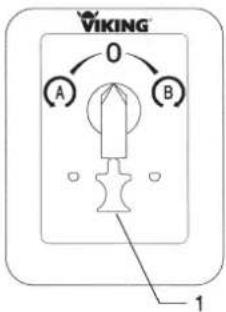

Reglage: vänster; A
natural_image
Diagram showing a screwdriver being inserted into a socket, with no text or symbols present.
Lagring
2002/96/EC, 2004/108/EC, 2006/95/EC
2156au001

Laitteen kuvaus
Vipu: vasemmalle; A
natural_image
Diagram of a screwdriver being inserted into a socket, showing the tool's rotation (no text or symbols present)21584001
natural_image
Diagram of a screwdriver being inserted into a socket, showing the tool's rotation (no text or symbols present)Rigtig drejeretning
2002/96/EC, 2004/108/EC, 2006/95/EC

natural_image
Diagram of a screwdriver being inserted into a socket, showing the tool's rotation (no text or symbols present)natural_image
Diagram of a screwdriver being inserted into a socket, showing the tool's rotation (no text or symbols present)2002/96/EC, 2004/108/EC,
2006/95/EC
0478 215 9921 B