BS 105 E - Sander FESTOOL - Free user manual and instructions
Find the device manual for free BS 105 E FESTOOL in PDF.
Frequently Asked Questions - BS 105 E FESTOOL
User questions about BS 105 E FESTOOL
0 question about this device. Answer the ones you know or ask your own.
Ask a new question about this device
Download the instructions for your Sander in PDF format for free! Find your manual BS 105 E - FESTOOL and take your electronic device back in hand. On this page are published all the documents necessary for the use of your device. BS 105 E by FESTOOL.
USER MANUAL BS 105 E FESTOOL
The specified illustrations can be found at the beginning of the operating instructions.
Graphical symbols

Caution.
Danger!

Read the operating instructions/notes

or ear protection!
1 Intended use
As specified, the machines are designed for sanding wood, plastic, metal, fi ller and painted surfaces.
Materials containing asbestos must not be processed.
Use only original Festool accessories and Festool consumable material designed for this machine because these components are designed specifically for the machine. Using accessories and consumable material from other suppliers will most likely affect the quality of your working results and limit any warranty claims. Machine wear or your own personal workload may increase depending on the application. Protect yourself and your machine, and preserve your warranty claims by always using original Festool accessories and Festool consumable material!

The user is liable for damage and injury resulting from incorrect usage!
2 Safety instructions
2.1 General Safety Rules
WARNING! Read all safety warnings and all instructions. Failure to follow the warnings and instructions may result in electric shock, fire and/or serious injury.
Save all warnings and instructions for future reference.
The term „power tool" in the warnings refers to your mains-operated (corded) power tool or
battery-operated (cordless) power tool.
2.2 Tool-specific safety rules
- Hold power tool by insulated gripping surfaces, because the belt may contact its own cord.
Cutting a "live" wire may make exposed metal parts of the power tool "live" and could give the operator an electric shock.

Wear suitable personal protection equipment: ear protection to reduce the risk of damaging your hearing; protective goggles; protective gloves when handling tools and coarse materials
- Harmful/toxic dusts can occur during your work (e.g. lead-containing paint, some types of wood and metal). Contact with these dusts, especially inhaling them, can represent a hazard for operating personnel or persons in the vicinity. Comply with the safety regulations that apply in your country. Connect the electric power tool to a suitable extraction system. To protect your health, wear a P2 protective mask.
- The manufacturer's handling and processing instructions must be observed without fail if explosive or self-igniting dusts are likely to occur during sanding.
- Persons with long hair should wear a hair net while using the machine. Never work with baggy clothing.
- Make sure the mains cable always leads away from the rear of the machine.
- Never use worn, ripped or heavily clogged sand-ing belts.
- Only for AS/NZS: The tool shall always be supplied via residual current device with a rated residual current of 30mA or less.
2.3 Noise and vibration information
The typical values determined in accordance with EN 60745 are:
Sound-pressure level 87 dB(A)
Sound-power level 98 dB(A)
Measuring uncertainty allowance K = 3 dB

ear protection!
Overall vibration levels a_n (vector sum for three directions) measured in accordance with EN 60745:
Handle a_h < 2.5m / s^2 K = 1.5m / s^2
Auxiliary handle a_h = 6.0 ~m / s^2 K = 2.0 ~m / s^2
The specified emissions values (vibration, noise)
- are used to compare machines.
- They are also used for making preliminary estimates regarding vibration and noise loads during operation.
- They represent the primary applications of the power tool.
Increase possible for other applications, with other insertion tools or if not maintained adequately.
Take note of idling and downtimes of machine!
3 Power supply and start-up

Observe mains voltage: the voltage and frequency of the power source must correspond to the specific cation on the machine rating plate.
In North America, only Festool machines with the voltage specifications 120V / 60Hz may be used.
On/Off switch
Switch (1.3) serves as an On/Off switch (press = ON, release = OFF). It may be latched with the locking knob on the side (1.2) for continuous operation. Pressing the switch again releases the lock.
4

Machine
settings
Always remove the power supply plug from the socket before carrying out any work on the machine.
4.1 Speed adjustment (BS 105 E)
You can adjust the speed stepplessly using the adjusting wheel [2.5]. This enables you to optimise the cutting speed to suit the material (see table). Several factors influence the sanding speed (e.g. workpiece consistency, sanding belt and grit manufacturer, skill of the user) and so tests must be performed before sanding work commences to establish the best speed.
The values listed in the table are only recommended.
| Application | Rotary control setting | Abrasive grit |
| Solid wood 4 - 6 100 | ||
| Veneer 3 - 4 120 | ||
| Chipboard 5 - 6 100 | ||
| Plastics 1 - 4 100 | ||
| Steel 2 - 4 80 | ||
| Removing paint | 1 - 3 24 |
4.2 Changing tools
- Push the lever (3.6) forwards to slacken the sanding belt.
- Remove the old sanding belt.
- Attach a new sanding belt.
Important: When inserting the sanding belt, make sure that the running direction of the belt (usually indicated by an arrow on the inside) matches the running direction of the machine [3.5].
- Return the lever (3.6) to its original position.
- Switch on the machine and check that the sanding belt is running smoothly. The sanding belt must run centrally across the sanding base [3.4]. If this is not the case, use the rotary knob [3.1] to adjust the position of the sanding belt.
4.3
Dust extraction

Always connect the machine to a dust extractor when performing work that generates dust.
Inboard extraction
Slide the connector (4.3) on the dust bag (4.1) onto the extractor opening (4.2) and turn clockwise to secure.
Make sure that the plate springs (4.5) touch the belt casing on the machine.
Turn the connector anticlockwise to remove and empty the bag.
External extraction by an extraction unit
Attach the adapter (4.4) to the extractor opening (4.2) instead of the dust bag.
A Festool dust extractor with an extractor hose diameter of 36mm or 27mm can be connected to the adapter.
4.4 Cooling air
Position the air guide flap (1.1) so that the escaping air does not disturb you.
5 Working with the machine
- Only switch off the machine when lifted from the workpiece.
- Only guide the machine along the workpiece when switched on. Only switch off the machine once you have lifted it off the workpiece completely.
- Before putting the machine down, always switch it off and wait until it has stopped completely.
-
Always secure the workpiece in such a manner that it cannot move while being sawed.
-
The machine must always be held with both hands by the designated handles [1.4, 1.5].
Metalworking

The following precautions are to be taken when processing metals for safety reasons:
- Pre-connect a residual current circuit-breaker (FI, PRCD).
- Connect the machine to a suitable dust extractor.
- Clean tool regularly of dust accumulations in the motor housing.
- Wear protective goggles.
- Sanding metal generates flying sparks. Make sure that sparks do not pose a risk for other persons. Flammable materials located within the range of flying sparks pose a fire hazard and should be removed immediately.
Operating instructions
Apply minimal pressure when working with the machine. The weight of the machine should be sufficient.
Work at a steady pace. Guide the machine in parallel, overlapping sanding strokes along the workpiece. Sand in the direction of the grain to achieve a better surface quality.
When sanding paint, clean the workpiece surface regularly so that paint dust does not clog the sanding belt.
Once used on metal surfaces, sanding belts should not be used on any other material.
5.1 Stationary use (partly accessories)
- Attach both feet [5.3] via the two threaded holes [4.6]. Important: the straight edges of the feet must face inwards.
- Make sure that the machine is standing firmly: use clamps to attach the feet to the base.
5.2 Longitudinal stop (partly accessories)
- Attach the longitudinal stop to the threaded hole (5.2) using screw (5.1).
- Unscrew the screw [6.3] to adjust the position of the longitudinal stop along the sanding belt.
- To sand sloping surfaces, unscrew the screw (6.2) and adjust the longitudinal stop. The scale (6.1) indicates the angle setting.
5.3 Sanding Assembly
frame
(partly accessories
Worn the power supply is shut off automatically, and the tool comes to a standstill.
terpiece [2.2] on the height adjuster must rest underneath the spring (2.1).
- Push the machine downwards towards the grooves (2.4) until the counterpartpiece (2.2) latches into position.
Removal
- Push the knurled screw [2.7] downwards until the counterpartie [2.2] pops out of the notch.
- Remove the machine from the sanding frame.
Note: the position of the sanding frame guide elements [2.4] is set in the factory. Do not detach them from the machine!
Working with the sanding frame
Adjust the height of the sanding frame using the knurled screw [2.7]. Increase the cutting depth (the distance the sanding belt protrudes over the edge of the sanding frame) by turning the screw in the direction of the plus sign. One turn of the knurled screw corresponds to 0.4mm .
Practical hint: use a test workpiece to set the sanding frame to the correct cutting depth.
When work is complete, push the eccentric clamp [2.6] towards the machine until it latches into position. The machine is raised above the workpiece. When you return the eccentric clamp to its original position, the preset cutting depth is the same as before.
6 Maintenance and care

Always remove the power supply plug from the socket before carrying out any work on the machine.

All maintenance and repair work which requires the motor casing to be opened may only be carried out by an authorised service centre.

Customer service and repair. Only through manufacturer or service workshops: Please find the nearest address at: www.festool.com/Service

Use only original Festool spare parts! Order No. at: www.festool.com/Service
Always keep the machine and the ventilation slots clean.
The tool is fitted with special motor brushes with an automatic cut-out. When the brushes become
swn the power supply is shut off automatically and the tool comes to a standstill.
The sanding base [3.4] must be replaced if the graphite coating is worn. Unscrew the three screws [3.2] and remove the retaining strip [3.3].
7 Accessories, tools
The order numbers of the accessories listed below can be found in the Festool catalogue or on the Internet under "www.festool.com".
Sanding base
A sanding base specially designed for heavy-duty sanding work and maximum material removal is available.
Sanding belts
- Synthetic-resin bonded X fabric sanding belts: sanding wood, fi breboard, iron, sheet steel, nonferrous metals and light alloy.
- Combination sanding belts: removing coatings and concrete residues, sanding plastered surfaces.
8 Disposal
Do not throw the power tool in your household waste! Dispose of the machine, accessories and packaging at an environmentally-responsible recycling centre! Observe the valid national regulations.
EU only: European Directive 2002/96/EC stipulate that used electric power tools must be collected separately and disposed of at an environmentally responsible recycling centre.
Information on REACH: www.festool.com/reach

Ponceuse à bande
7 Accessoires, outfits
JeHTouHaaJInΦMaunHka
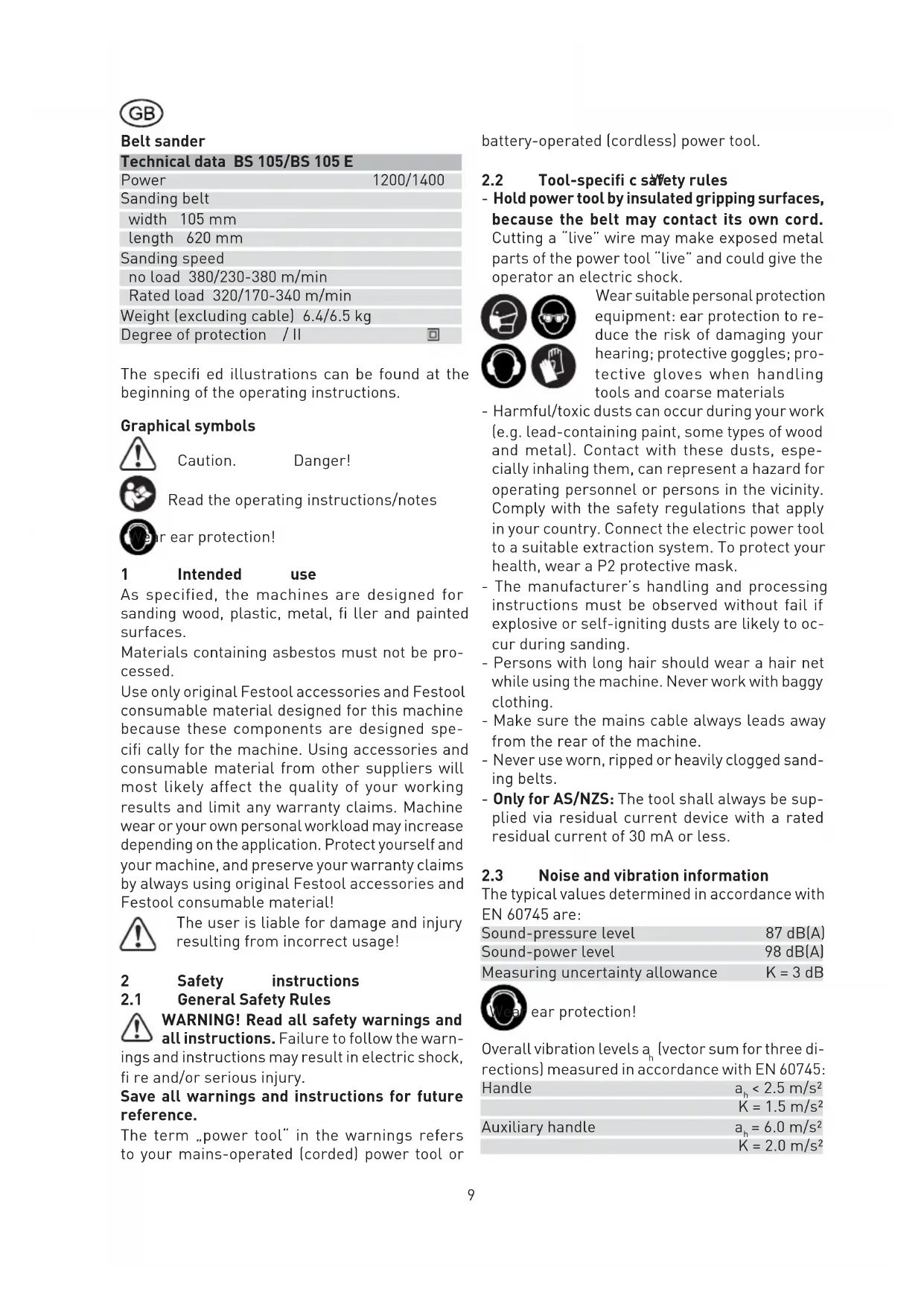
TexHnueckne daHHbIe BS 105/BS 105 E
MOUHOCTb 1200/1400
UJnfoBaJIbHaJaIeHTa
UnpHa 105MM
Динha 620 MM
CkopoocTb wJlnfoBaHn
xOIOCToXoD 380/230-380 M/MnH
PnHOMHaJIbHoI
Harpy3Ke 320/170-340 M/MnH
Macca [6e3 ka6e] 6,4/6,5 Kr
Be30nacHoCTb /II
Ppnilaraemble nllnctpaunn HaxoTcB NaaepykoBOndBa no 3KcnIyaTaun.
CNMBOJIbI

Ppeynpexdeneo6 ooue onaocctn

Co6nIaTe pyKOBoDCTBO NO 3KcNpyTaTUN/HHCTpyKUn!

Hocntb 3aunty opraHOB cnlyxa!

1 PnmeHne no Ha3HaueHHIO
Даннаяшлфmaшина npedha3haueha Дя Вьлолненяшлфовалых pa6ot "B cyxyo" noDepeby,плactмасe,metaIly,шnatleBke,aTakxe JAKOKpacouhblIM NOKpbITnM. Ac6ecTOco-derkaиne matepnaIbI obpa6abIbAtb 3anpe-zaetc.NcnoIb3yIte TOnbko npedha3haueHHbIeДЯ daHHo MaunHbI opuHaJIbHbIe OCHAcTKU pacxOdHbIe MatepnaIbI Festool,tak KAK 3TN KOMnoHEtbl ONTMaJIbHO corlaocBaHbI Mexdy co6oB. B clyuae icNoIb3OBAHnO ochCTKN pacxOdHbIXMatepnaIbOB npuN3BOJnteNe CneDyET npINHMaTb BO BHIMaHHe BO3MOXHOCTb CHHXeHHa KaeeCTBa pa6tBI n OrpaHnueHn NO rapaHTNHbIM o6a3aTeJIbCTBam.B 3abNCmOCTn OT BnDa pa60rTO MOKET npINBeCtN K 6OJIee nHTeHCNBHOmy n3HOCy MaunHbI nII K yBEJIuYeHIO Harpy3Kn Ha pykn. POnToMy IJIr TORO, YTO6bl c6peeyCb BoON Cnbl, ONTMaJIbHO NCNoJIb3OBAtbp pecypc MaunHbI n ObecneHTb HaJeXHoCTb rapaHTNHbIX o6a3aTeJIbCTB, npImeHnTe TOnbKO opuRnHaJIbHbIe OCHAcTKU pacxOdHbIe MatepnaIbI Festool!

HCTpyMeHT cKOHcTpynpOBAH nIy npo- ceCCNoHaJIbHOrO npmHeHn.
3a yuepe6 n HeecactHbIe cIyuaI, CBra3aHnHbIe C npimHeHneM He no Ha3HaueHnIO,OTBeuayet OJb30BaTeJIb.
2 Yka3aHnI NO TexHnke 6e3oNaChocTn
2.1 06uye yka3aHnno 6e3oNaChocTn
BHIMAHHEBpoHTe Bcyeka3aHnno no Texnke 6e3oNaChoctn n peKOMeHaauu.
Oun6kn npn co6nHneHH npNBedeHHbIX yka3aHnn n peKomeHdaCm MOyT npNBecTN K nopaxeHnO 3NeKTPnueckm TOKOM, noXapy, n/nn Bbl-3BaT TBJxKeJIbIe TpaBMbl.
CoxpaHЯTe Bce yKa3aHnNo TExHnKe 6e3oNaCHoCTn N PyKOBODCTBa No 3KcNpyaTaunB KaueCTBe cnpaBoOHorO MaTePnAna.
NcnoJb3OBAHHoe B HactoUx INHCTpyKUnx I yKa3aHnIX NOHATne «3NeKTponHCTpyMeHT» pacnpoctpaHReTcra Ha 3NeKTponHCTpyMeHT C nTuHaHEm OT cETn [co uHypom nTuHaHr O T 3NeKTpocetn] nHa aKKyMylTophB i 3NeKTponHCTpyMeHT (6e3 shHypom nTuHaHr OT 3NeKTpocetn).
2.2 CnueuΦnueckne npabunla TexHnKn 6e3- onaChocTn
-ДерхиTe 3нeКТponHCTpymENT 3a n30npoBaHnBie pyuK,Тak KaK ΦлнфОваьнЯ ЛeHTa MoXkET NOВpeДNTb co6cTBeHHbI ψHyp nITaHnI.
2.3 DaaHbIe no uMy n Bn6paun
OnpeJeHbIe B coOTBeTCTBUN c EN 60745 TnIOBbIe 3HaueHn:
YpoBEnbWyma 87D5(A)
3BykoBaMoUHocTb 98dA
Donyck Ha norpeuHocTb n3MepeHHa K=3dB

Tb 3aunTy opranHOB clyxa!
06uKo3ΦnueHr KOle6aHn ah (cymma BeKTOpOB Tpex HAnpaBHeHn) paccHTbIBAeTcB COOTBeTCTBnC EN 60745:
PykoTka a<2,5m/c²
IorpeuHocb K=1,5M/c²
IorpeuHocb K=2,0m/c²
Yka3aHHbIe 3HaueHn ypoBna/wn6paun
-cnykataIcpaBHeHHnHCTpyMeHTOB;
-MoXHo TaKKe IcNoJIb3OBA TbДЯпpeDВapuTeIbHOn OueHKn WymOBOn N Bn6paCnoHHOHarpy3Kn BO BpeMra60TbI;
- OTPaKaIOT OCHOBHeIe 0bIaCTn npIMeHnIe 3JIeKTpOuHcTpyMeHTa.
Pn nCnoJb3ObaHnn MaunHKN B dpynx ceJnx, C dpyrmn CMeHHbIMn (pa6oynm) HNCTpymeHTamn nnB cIyuae nx HeydOBnetBopntelhoro 06cIyKINBaHna WymoBa n BN6paunOHnHa rhpz3Kn MoRyt Bo3pacta. Co6IIOaIte 3NaueHn BpeMeHn pa6oTbHa XoIoocToM xOdy N BpeMeHn NepepbIOB B pa6ote!
3 ΘeKtpnuecKoe nOdkNIOUeHne N BBOB B KcnpyaTaunio

Co6IHOaIte ceTeBoe HApJxKeHne:HaI npJxKeHne B cETn DOJIxHo COOTBeTcTBoBaTb 3HaueHnM, yKa3aHHbIM Ha 3aBOdCKoI Ta6NHyKe MaunHbl.
B CeBepHoi Amepnke MoXHo NcNoIb3oBaTb ToIbKO MaunHbI Festool c xapaKTePncTnKo I no HanpJxHeHIO 120 B/60 T.
YCTAHOBNTe BO3dyxONpOBOJn KJanaH (1.1) TaKIM 6pa30M, YTO6bI BblOJn OXJaKaIOuNt Bo3dyx He Meaan pa6oTaTb.
5 BbINOJIHeHne pa6oT c nOMoIbIO MaINHbI
- Pn BkIoueHm MaunHbI depXnte ee Ha HeKoTOpom paCtOaHnn OT o6pa6aTbIbAemoi NobepxHOCTn.
-ПОДВODINTe MaSHInHy K O6pa6aTbIbAeMoJ DeTaJIH ToJIbKO BO BKJIQUeHNHom COcToRanHn. BbIKJIQUaHTe MaShInHy ToJIbKO Torda, KorDa OHa He KaCaetcJ DeTaJIH. - Ipeen Tem KaK OTLOXHTb MaunHy, BblKJIouHte ee N noOxNTe, noka OHa He octaHOBNTc.
-Bcerda ykpennIte 6pa6aTbIBaemyo nTeaIb TaK, UTo6bOHa He DnBraIacb npu 6pa6oTke. - Bcerda āperknte MaunHy dBym pykamn 3a npedHa3HaueHHbIe nla 3ToRo pyuKn (1.4, 1.5).
06pa6oTkaMeTaJIIOB

Pn 6pa6oTke metanloB B ceJx co- 6JIIOeHnI npaBnI be3ONaCHOCTn CneJeT BbInONHt cNeDyUOuNne npEINncAHn:
-ПодклIoUHTe BыКЛIOUaTeIb 3aIuNTbI OT npeBbl-шеня ToKa [FI,PRCD).
-NodknHouHte MaunHy K NoDxOJaIeMy yCTpoiCTBy dJIy OTCaCbIBaHNr NblN.
- PerylarypHo ouHsauTe MaunHy ot OTloXeHn NblN B Kopnyce 3JeKToDnBraTeJIa.
- Pa6oTaIeB 3aUHTbIX OUYkax.
- Ppi shnfoBaHH metaJIHuecknx nobepx-HocTe npoIcxOHT nCKpeHne. PpIMute MepbI Bo n36ExKaHHe TpaBMnpOBaHH JIOJeN. N3-3a ONaCHOCTH BO3RopaHH N6JIN30CTN (B 30He NCKpeHH) He doJHKbI HaxOHTbcra RopUOHe MaTePnaJIbI.
Pon3BODCTBeHHbIe yKa3aHnA
BoBpeMa pa6oTbI ycnIne c BaWei cToPoHbI OJXHO 6bITb MInHmAlNbHbIM. OcTaToUHO co6CTBeHHoro Beca MaunHbI.
HanpaBraIte MaunHy paBHomepHo. Beinte ee
no napalneIbHbIM, nepeKpbIbAIOUIMcra yuactKam o6pa6aTbIBaEMo IeTaII. Iyra obecneueHnBbICOKOrKaueCTBa NOBepxHOCTN pOn3BOIDTeWlnΦOBAHne no HapabJIeHNIO BOLOKOH.
Bo BpemufoBaHnpeyIrpHo ouuauTe noBepxHOCTb OT CHrTOrO JaKa Bo n36exaHne 3acopeHHu foBaJIbHoJ HeTbI.
He nCnoIb3yInTe ⅢnΦOBAJIbHyIO JeHTy nocJe o6pa6oTKa MetaJIJa IJIA WnΦOBAHnI NOBepxHocTe IN3 dpyrnx MaTePnaNoB.
5.1 CtaunohapbI pexm (aactnHoc-Hactka)
- 3aKpeNte o6e HoKKn (5.3) Ha pe3b6ObIx OTBepCTnX [4.6]. BHMaHne: npMaIe cTOpOnbl HoxKe I0JXHbI 6bITb 6paueHbI BHyTpB dpyr Kdpyr.
- Hanaekho 3aΦnKcnpyTe MaunHy: 3akpennte HOKKHa OCHOBAHnn Pn NOMOuN ctpbunH.
5.2 PpOdoJIbHbI ynop (aCtNuaO OcHaCTKa)
-3aKpeHnTe npoJbHbI ynp np Ni NMOU BUNTa [5.1] uepe3 pe36OBoe OTBepCTne [5.2].
- OTKpyTnB BnHT (6.3), Bbl CMOxKeTe nepemeaTaB npoOJIbHbI yOp B nIOCKOCTn WJNΦOBaJIbHOJ JeHTbl.
-ДяшлфоваяскocobВblcmoхete nobopa- yBaT npoOJIbHbI yNop,OTKpyTNB BnHT (6.2). ⅢkaIa (6.1) noka3bIbAeT bIb6paHHbI yroI.
5.3 WlnfoBaIbHa paMaKa (aactnHoo cHaCTka)
MOHTaK
-COBmecnte na3bI (2.4) MaunHbC BbICTyamn (2.3) ⅢnΦoBaJIbHo paMKn. ⅢapHnpHbM eXaHN3M (2.2) perynpoBKn no Bbcote dOJxKeH npIneratb K HxKHe cToPoHe npxKnHb [2.1].
- HaxmajTe Ha MaunHy B HanpaBneHn Na3OB [2.4], noka He ycbluHTe ueJyok fNKcaunn shapHnpHoro MexaHn3Ma (2.2).
ДемоNTаж
-Haxmaite Bn3 BnHT (2.7) c hakatnoi roIOB-ko, noka wapnphmy mexaHn3M (2.2) He bI-ndT n3 3auePJIeHnJ.
- ChnmuTe MaunHy c wlnΦOBaIbHoi paMkn.
Yka3aHne: HanpaBnaIooNe (2.4)ДЯшлфOBaIb-HoH paMkn OTpeRyInpObaHbHa 3aBoJe. I03ToMy He cIeIyET n3MeHrTb IN NOLOKeHne!
Pa60Ta c 7nfoBaJbHo paMKoI
PerynpoBka wlnfoBaIbHOB paMKn no Bbcote npon3BoDntc npn nOmoU BNHTa (2.7) cHaKaTHo rOIOBko. fny6bHa o6pa60TKn (BbICTyn WlnfoBaIbHOJIeHTb I NaIpaMkoYBEJInuBaETc npn BpaueHH B HaprabHeHH NlIOca. Odn H 6OpOT BNHTa n3MeHReT fny6bHy Ha 0,4 MM.
PpmeaHne: nCnoJb3yIte npo6HyIO 3arOToBky IJIra TOrO, yTO6bl yCTaHOBnTb IINΦOBaJIbHyOp pAMKy Ha ONTMaJIbHyIO rny6uHy.
NocJIe 3aBepWeHnpa60bHaXMMte Ha 3KcCHeHTpNKOBbI pbUar (2.6)do 7eJyKa B HApPaBHeHmMaunHb.I Bpe3yNbTaTe 3TOro MaunHa npnOHNMeTcHa nD o6pa6aTbIbAemOn NobepxHocTbIO.BepHyB 3KcCHeTpNKOBbI pbUar B IxCxOdHoe NIoJoxHne,Bi cHOBa NOLyUHTpe paHee BbIbpaHHyIO rny6uHy o6pa60TKn.
6 06cnyxmbHne uyxo

IpeH hauanom IIO6o pa60tbc Maun-HoB Bcerda BbIHMaTe WTeNceJb n3 po3etkn!

Bce pa60tI no 6cnykuaHIO npmoHTy, KOToPbIe Tpe6yeT OTKpbIbAHnK Kopnyca DBrIaTeJI, MoYr Ipn3BOIDTBcra ToIbKO abTopu3OBAHHo MaCTepCKoN cepBnCHOH cnJx6bl.

CepBnchoe 06cIyXnBaHne n peMoHT TOnbKO uepe3 cInpMy- N3rToTOBnTeJIa HnB HaUnx cepBnChbIX MaCTepCKNX: aDpec 6JnKaJWei MaCTepckOi CM. Ha WwW. festool.com/Service

IcnoIb3yIteToJIbKOoprHnHaJIbHbIe3a-nachIbe yactn Festool!NoIra 3aKa3a Ha: www.festool.com/Service
Дя obecneueHn CnpkyIaun Bo3dyxa, Bce OxJaIauIe OTBepCTnB Kopnyce DnraTeJn DOJIKHbI 6bITb NocToAHNoYcTbIMN cBO6OdHbIMN. Pnp6Op OCHaIeH CneuHaJIbHbIM yIeM dIyABTOmatNueCKOro OKJIIOUeHn. Korda OH n3HaUNBaETcR, pONCXODT ABOMa-TNUeCKoe OTKIOUeHne TOka, n np6Op npekpaaaet pa60TaB. B clyae CTnpaHnra TpaΦntoBOrO nOKpbITnH He-OBxOdmo 3aMeHHTb ONOPHyIO nlaCTnHy [3.4].ДЯ 3TORO oTKpyTnte Tprn BInTa (3.2) n CHmMtpe npIXHMHy IO nnAHHky (3.3).
7 PpHaJaleXHocTn, HcTpymeHtbl
KoIbI 3aKa3a onNcBlaBaEmbIX dAlee npHaJaleXHoCTe npVeDeHb I B kataIore Festool n B INHTepHET no aDpecy .www.festool.com".
Onopnay nlaCTnHa
Дя rpy60ошлфовнс CBbICOKO npo3BO-DntelbHocTBcEma npeJnaraetc onopnaIJIaCTnHa.
UHnΦOBaJIbHbIeJeHTbI
-TkaHeBbIe WJnfoBaJIbHbIe JeHTbIX Ha oCHOBe CHTeTnuecknx CMOJ: WJnfoBaHne IpeBecnbl, TBepdbIX BOJOKHcTBIX NIT,KeJe3a,IInCTOBOIC TaJI, UBeTHbIX IN JERKINX MetaJIIOB.
- Kom6HnHpoBaHHbIe ⅢnfoBaJIbHbIe JeHTbl: ydaJIeHne Kpackn n octaTKOB 6eToHa, IINFOBAHHe rncobix nobepxHOCTeN.
8ytin3aun
He Bb6paCbBaIte 3JeKTpOuHcTpymeHtBi BMeCTe C6bITOBbIMN OTxOaMn! 06ecneUte 6e3oNaChyIOIra OKpyKaIOSeI cpebl yTINl3aUIO HcTpymeHTa, oChAcTKI uYaNokBKn. Co6JIOnaTe DeIcTByIOUIIne HaUNHOHaJIbHbIe INcTpkyUIN.
TolbkoДЯ EC: corlaacHo EbponeeckoДиpeKtInBe 2002/96/EG oTcIyJxNbUWe cBoi cpoK 3JIeKToHnCTpyMeNTbI DoJIxKbI yTIN3nPoBaTbC8 OTdJIbHO HnHaPabJIbTaC Ha 3KOJIoRnUHyO yTIN3aCInO.
HΦopMaζη no Σινεκτινe REACH: www.festool. com/reach