USER MANUAL DW707 DEWALT
Anvend horevaern, his lydniveaulet overstiger 85 dB(A).
AANNNNNEENNNNNNNNNNNNNNNNNNNNNNNNNNNNNNNNNNNNNNNNNNNNNNNNNNNNNNNNNNNNNNNNNNNNNNNNNNNNNNNNNNNNNNNNNNNNNNNNNNNNNNN

Overskrid aldrig dobbeltgeringsvinklerne pa 45^ vinkel med 45^ venstre aller hojre gering.
You have chosen a DeWALT product. Years of experience, thorough product development and innovation make DeWALT one of the most reliable partners for professional users.
Table of contents
Technical data en - 1
EC-Declaration of conformity en - 1
Safety instructions en - 2
Package contents en - 3
Description en - 3
Electrical safety en - 3
Mains plug replacement (U.K. & Ireland only) en - 3
Using an extension cable en - 3
Assembly en - 4
Adjustment en - 4
Instructions for use en - 5
Maintenance en - 7
Guarantee en - 7
Technical data
| | DW701 DW707 |
| Voltage V | 230 | 230 | | |
| (U.K. & Ireland only) | V | 230/115 | 230/115 |
| Motor power (input) | W | 1,600 | 1,200 |
| Motor power (output) | W | 1,100 | 800 |
| Blade diameter | mm | 216 | 216 |
| Blade bore | mm | 30 | 30 |
| Max. blade speed | min1 | 2,500-5,000 | 6,700 |
| Mitre (max. positions) | left and right | 48° | 48° |
| Bevel (max. positions) | left | 48° | 48° |
| Compound metre | bevel | 45° | 45° |
| mitre | 45° | 45° |
| Capacities | | | |
| cross-cut 90° | mm | 60 x 270 | 60 x 270 |
| mitre 45° | mm | 60 x 190 | 60 x 190 |
| mitre 48° | mm | 60 x 180 | 60 x 180 |
| bevel 45° | mm | 48 x 270 | 48 x 270 |
| bevel 48° | mm | 44 x 270 | 44 x 270 |
| Overall dimensions | mm | 460 x 560 x 430 | 460 x 560 x 430 |
| Weight | kg | 16 | 15.5 |
Fuses:
Europe 230 V tools 10 Amperes, mains
U.K. & Ireland 230 V tools 13 Amperes, in plugs
The following symbols are used throughout this manual:

Denotes risk of personal injury, loss of life or damage to the tool in case of non-observation of the instructions in this manual.

Denotes risk of electric shock.

Sharp edges.

DW701/DW707
DeWALT declares that these Power Tools have been designed in compliance with: 89/392/EEC, 89/336/EEC, 73/23/EEC, EN 50144, EN 55104, EN 55014, EN 61000-3-2 & EN 61000-3-3.
For more information, please contact DeWALT at the address below, or refer to the back of the manual.
Level of sound pressure according to 86/188/EEC & 89/392/EEC, measured according to EN 50144:
| | DW701 | DW707 |
| Lpa (sound pressure) | dB(A)* | 89.7 | 89.7 |
| Lwa (acoustic power) | dB(A) | 97.7 | 97.7 |
at the operator's ear

Take appropriate measures for the protection of hearing if the sound pressure of 85 dB(A) is exceeded.
Weighted root mean square acceleration value according to EN 50144:
| DW701 | DW707 |
| 2.5 m/s2 | 2.5 m/s2 |
TUV Rheinland
Director Engineering and Product Development
Horst GroBmann
X. fOpsman
DEWALT, Richard-Klinger-StraBe 40
D-65510, Idstein, Germany
Safety instructions
When using Power Tools, always observe the safety regulations applicable in your country to reduce the risk of fire, electric shock and personal injury. Read the following safety instructions before attempting to operate this product.
Keep these instructions in a safe place!
General
1 Keep work area clean
Cluttered areas and benches can cause accidents.
2 Consider work area environment
Do not expose Power Tools to humidity. Keep work area well lit.
Do not use Power Tools in the presence of inflammable liquids or gases.
3 Guard against electric shock
Prevent body contact with earthed surfaces (e.g. pipes, radiators, cookers and refrigerators).
For use under extreme conditions (e.g. high humidity, when metal swarf is being produced, etc.) electric safety can be improved by inserting an isolating transformer or a (FI) earth-leakage circuit-breaker.
4 Keep children away
Do not let children come into contact with the tool or extension cord. Supervision is required for those under 16 years of age.
5 Extension cords for outdoor use
When the tool is used outdoors, always use extension cords intended for outdoor use and marked accordingly.
6 Store idle tools
When not in use, Power Tools must be stored in a dry place and locked up securely, out of reach of children.
7 Dress properly
Do not wear loose clothing or jewellery. They can be caught in moving parts. Preferably wear rubber gloves and non-slip footwear when working outdoors. Wear protective hair covering to keep long hair out of the way.
8 Wear safety goggles
Also use a face or dust mask in case the operations produce dust or flying particles.
9 Beware of maximum sound pressure
Take appropriate measures for the protection of hearing if the sound pressure of 85 dB(A) is exceeded.
10 Secure workpiece
Use clamps or a vice to hold the workpiece. It is safer and it frees both hands to operate the tool.
11 Do not overreach
Keep proper footing and balance at all times.
12 Avoid unintentional starting
Do not carry the plugged-in tool with a finger on the switch.
Be sure that the switch is released when plugging in.
13 Stay alert
Watch what you are doing. Use common sense. Do not operate the tool when you are tired.
14 Disconnect tool
Shut off power and wait for the tool to come to a complete standstill before leaving it unattended. Unplug the tool when not in use, before servicing or changing accessories.
15 Remove adjusting keys and wrenches
Always check that adjusting keys and wrenches are removed from the tool before operating the tool.
16 Use appropriate tool
The intended use is laid down in this instruction manual. Do not force small tools or attachments to do the job of a heavy-duty tool. The tool will do the job better and safer at the rate for which it was intended.
Warning! The use of any accessory or attachment or performance of any operation with this tool, other than those recommended in this instruction manual may present a risk of personal injury.
17 Do not abuse cord
Never carry the tool by its cord or pull it to disconnect from the socket. Keep the cord away from heat, oil and sharp edges.
18 Maintain tools with care
Keep the tools in good condition and clean for better and safer performance. Follow the instructions for maintenance and changing accessories. Inspect the tool cords at regular intervals and, if damaged, have them repaired by an authorized DeWALT repair agent. Inspect the extension cords periodically and replace them if damaged. Keep all controls dry, clean and free from oil and grease.
19 Check for damaged parts
Before using the tool, carefully check it for damage to ensure that it will operate properly and perform its intended function.
Check for misalignment and seizure of moving parts, breakage of parts and any other conditions that may affect its operation. Have damaged guards or other defective parts repaired or replaced as instructed.
Do not use the tool if the switch is defective. Have the switch replaced by an authorized DeWALT repair agent.
20 Have your tool repaired by an authorized DeWALT repair agent
This Power Tool is in accordance with the relevant safety regulations. To avoid danger, electric appliances must only be repaired by qualified technicians.
Additional Safety Rules for Mitre Saws
- Make sure that the blade rotates in the correct direction. Keep the blade sharp. Do not use blades of larger or smaller diameter than
recommended. For the proper blade rating refer to the technical data.
- Make sure all locking knobs and clamp handles are tight before starting any operation.
- Check periodically that the motor air slots are clean and free of chips.
- Disconnect the machine from the mains before carrying out any maintenance work or when changing the blade.
Before using any accessory consult the instruction manual. The improper use of an accessory can cause damage.
- Allow the motor to reach full speed before cutting.
- Raise the blade from the kerf in the workpiece prior to releasing the switch.
- Do not wedge anything against the fan to hold the motor shaft.
- Never place either hand in the blade area when the saw is connected to the electrical power source.
- Do not attempt to cut excessively small pieces.
- Never attempt to stop a machine in motion rapidly by jamming a tool or other means against the blade; serious accidents can be caused unintentionally in this way.
- Do not use cracked or damaged saw blades.
- Do not cut ferrous materials or masonry with this saw.
- Do not use any abrasive discs.
Residual risks
The following risks are inherent to the use of metre saws:
Injuries caused by touching the rotating parts In spite of the application of the relevant safety regulations and the implementation of safety devices, certain residual risks cannot be avoided. These are:
Impairment of hearing.
- Risk of accidents caused by the uncovered parts of the rotating saw blade.
- Risk of injury when changing the blade.
- Risk of squeezing fingers when opening the guards.
- Health hazards caused by breathing dust developed when sawing wood, especially oak, beech and MDF.
Package contents
The package contains:
1 Partly assembled machine
14 mm Allen key
16 mm Allen key
1 216 mm TCT saw blade
2 Coach bolts
1 Fence insert (with 2 screws)
1 Instruction manual
1 Exploded drawing
- Check for damage to the tool, parts or accessories which may have occurred during transport.
- Take the time to thoroughly read and understand this manual prior to operation.
- Remove the saw from the packaging material carefully.
Description (fig. A1 & A2)
Your DeWALT Cross-Cut Mitre Saw has been developed for professional applications. This high precision machine can be easily and quickly set to crosscut, bevel, metre, or compound metre. Placing the workpiece on a piece of wood will increase the capacities to 300 mm.
A1
1 ON/OFF-switch
2 Head lock up release lever
3 Carrying handle
4 Fixed upper guard
5 Outer flange
6 Blade bolt
7 Lower blade guard
8 Fence insert
9 Fixed table
10 Blade slot
11 Positive stop lever
12 Mitre clamping knob
13 Rotating table/mitre arm
14 Mitre scale
15 Fence
16 Upper dust extraction nozzle
A2
17 Traverse lock
18 Head lock up hook
19 Bevel clamp handle
20 Bevel scale
21 Bench mounting holes
22 Lock down button
23 Traverse bars
24 Saw head
Optional Accessories
A3
25 Table end plate
26 Support guide rails
27 Material support plate
28 Material clamp
29 Swivelling stop
30 Adjustable stand 760 mm (max. height)
31 Legstand
A4
32 Length stop for short workpieces (to be used with guide rails [26])
A5
31 Legstand
33 Roller table
Electrical safety
The electric motor has been designed for one voltage only. Always check that the power supply corresponds to the voltage on the rating plate.
Mains plug replacement (U.K. & Ireland only)
- Should your mains plug need replacing and you are competent to do this, proceed as instructed below. If you are in doubt, contact an authorized D=WALT repair agent or a qualified electrician.
- Disconnect the plug from the supply.
- Cut off the plug and dispose of it safely; a plug with bared copper conductors is dangerous if engaged in a live socket outlet.
- Only fit 13 Amperes BS1363A approved plugs fitted with the correctly rated fuse (1).
- The cable wire colours, or a letter, will be marked at the connection points of most good quality plugs. Attach the wires to their respective points in the plug (see below). Brown is for Live (L) (2) and Blue is for Neutral (N) (4).
- Before replacing the top cover of the mains plug ensure that the cable restraint (3) is holding the outer sheath of the cable firmly and that the two leads are correctly fixed at the terminal screws.
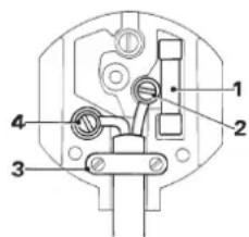

Never use a light socket.
Never connect the live (L) or neutral (N) wires to the earth pin marked E or 1一
For 115V units with a power rating exceeding 1500W , we recommend to fit a plug to BS4343 standard.
Using an extension cable
If an extension cable is required, use an approved extension cable suitable for the power input of this machine (see technical data). The minimum conductor size is 1.5mm^2
When using a cable reel, always unwind the cable completely.
Also refer to the table below.
| Conductor size (mm2) Cable rating (Amperes) |
| 0.75 6 |
| 1.00 10 |
| 1.50 15 |
| 2.50 20 |
| 4.00 25 |
| Cable length (m) |
| 7.5 15 25 30 45 60 |
| Voltage Amperes Cable rating (Amperes) |
| 230 0 - 2.0 6 6 | 6 | 6 6 | 6 | | |
| 2.1 - 3.4 6 6 | 6 | 6 6 | 6 | |
| 3.5 - 5.0 6 6 | 6 | 6 10 15 | | |
| 5.1 - 7.0 | | 10 10 10 10 15 15 | | |
| 7.1 - 12.0 | | 15 15 15 15 20 20 | | |
| 12.1 - 20.0 | | 20 20 20 20 25 - | | |
| 12.1 - 20.0 | | 20 20 20 20 25 - | | |
Assembly

Prior to assembly always unplug the tool.
The motor and guards are already assembled onto the base.

The nozzle (16) of the upper fixed blade guard is fitted in the factory.
- Insert the middle dust extraction nozzle (34) as shown.
- Secure the lower dust extraction nozzle (35) using the screws (36).
- Fit the hoses (37) to the nozzles; the longer hose to nozzle (16).
- Connect the hoses to the 3-way connector (38).
- Whenever possible, connect a dust extraction device designed in accordance with the relevant regulations regarding dust emission.
Fitting the fence insert (fig. A2 & C)

Always use the litre insert for all cuts!
- Push the saw head (24) down to pull out the lock down button (22) and raise the saw head (fig. A2).
- Insert the screws (40) and washers (41) into the holes (39) as shown to mount the fence insert (fig. C).
Cable clamp (fig. D)
- Insert the cable (42) into the cable clamp (43). Allow enough cable for the saw head travel.
Bench Mounting (fig. E)
Your saw can be mounted on any flat and stable surface.
The recommended work height, however, is 700 to 750mm
- Insert the two coach bolts (45) into the two holes (21).
Always mount your saw firmly to prevent movement.
Mounting the saw blade (fig. A1, F1 & F2)

The teeth of a new blade are very sharp and can be dangerous.
- Press the spindle lock (44) and rotate the blade by hand until you feel the lock engage. Continue to hold the spindle lock in to keep the blade from turning (fig. F1).
- Using the 6 mm Allen key, loosen the blade bolt (6) by turning clockwise. Remove the blade bolt (6), its washer and the outer flange (5) (fig. A1).
- Press the combined lower guard and head lock up release lever (2) to raise the lower blade guard (7) and remove the saw blade (45) (fig. F2).
- Install the new saw blade (45) onto the shoulder (46) provided on the inner flange (47) making sure that the teeth at the bottom edge of the blade are pointing towards the fence (away from the operator) (fig. F2).
- Replace the outer flange (5), making sure that the location lugs (48) are engaged correctly, one on each side of the motor.
- Tighten the blade bolt (6) by turning counter-clockwise while holding the spindle lock (44) engaged with your other hand (fig. F1).

Never press the spindle lock while the blade is rotating.
Adjustment

Prior to adjustment always unplug the tool.
Your Mitre Saw was accurately adjusted at the factory. If readjustment due to shipping and handling or any other reason is required, follow the steps below to adjust your saw. Once made, these adjustments should remain accurate.
Adjusting the traverse bars for constant cutting depth
(fig.A2,F1,G1&G2)
The blade must run at a constant cutting depth along the full length of the table and must not touch the fixed table at the rear of the slot or at the front of the rotating arm. To achieve this, the traverse arms must be perfectly parallel to the table when the saw head is fully depressed.
- Press the combined lower guard and head lock up release lever (2) (fig. F1).
- Press the saw head fully to the rear position and measure the height from the rotating table (13) to the bottom of the outer flange (5) (fig. G1).
- Press the unlock symbol of the saw head traverse lock (17) (fig. A2).
- Keeping the saw head fully depressed, pull the head to the end of its travel.
- Measure the height indicated in figure G1 again. Both values should be identical.
If adjustment is required, proceed as follows:
- Loosen the locknut (49) in the bracket (50) under the upper dust extraction nozzle (16) and adjust the screw (51) as required, proceeding in small steps (fig. G2).
- Tighten the locknut (49).

Always check that the blade does not touch the table at the rear of the slot or at the front of the rotating arm at 90^ vertical and 45^ bevel positions. Do not switch ON before having checked this!
Checking and adjusting the blade to the fence (fig. A2, H1 - H4)
- Loosen the litre clamping knob (12) by turning counterclockwise (fig. H1)
- Pull down the head and lock it in this position using the lock down button (22) (fig. A2).
- Lift the positive stop lever (11) and swing the head until the stop locates it at 0^ litre position. Do not tighten the clamping knob (12) (fig. H1).
- Check that the two 0^ markings (52) on the scale (14) are just visible (fig. H2).
- Place a square (53) against the left side of the fence (15) and blade (45) (fig. H3).

Do not touch the tips of the blade teeth with the square.
- If the saw blade is not exactly at 90^ to the fence:
- Loosen the two screws (53) and move the scale/head assembly left or right until the blade is at 90^ to the fence as measured with the square (fig. H4).
- Lock the metre clamping knob (12) (fig. H1).
- Tighten the two screws (53) (fig. H4).

Make sure the rear edge of the metre scale keeps in contact with the two location lugs (54) at all times.
Checking and adjusting the blade to the table (fig. A2, J1 - J3)
- Ensure that the head is locked in the 0^ litre position.
- Release the bevel clamp handle (19) by pushing it down (fig. A2).
- Press the saw head to the right to ensure it is fully vertical and tighten the bevel clamp handle (19).
- Place a set square (53) on the table and up against the blade (45) (fig. J1).

Do not touch the tips of the blade teeth with the square.
If adjustment is required, proceed as follows:
- Loosen the bevel clamp handle (19) (fig. A2).
- Using an Allen key, adjust the screw (55) as required (fig. J2).
- Check that the bevel indicator (56) indicates 0^ on the bevel scale (20) (fig. J3).
- If not, loosen the two screws (57) move the scale (20) as required and tighten the two screws.
Checking and adjusting the bevel angle (fig. J3, K1 & K2)
Your saw has a bevel adjustment handle with knurled end (58) that allows the fixed position to be set at 45^ or 48^ as required (fig. K1).
-Out = 48^
- = 45^

While performing this adjustment, it is advisable to take the weight of the saw head by holding it. This will make it easier to turn the adjustment screw.
Instructions for use

- Always observe the safety instructions and applicable regulations.
The attention of UK users is drawn to the "woodworking machines regulations 1974" and any subsequent amendments.
- Ensure the material to be sawn is firmly secured in place.
- Apply only a gentle pressure to the tool and do not exert side pressure on the saw blade.
- Avoid overloading.
Prior to operation:
- Install the appropriate saw blade. Do not use excessively worn blades. The maximum rotation speed of the tool must not exceed that of the saw blade.
- Do not attempt to cut excessively small pieces.
- Allow the blade to cut freely. Do not force.
- Allow the motor to reach full speed before cutting.
- Make sure all locking knobs and clamp handles are tight.
Switching ON and OFF (fig. L1 & L2)
DW701 - Setting the electronic speed control dial
This model is fitted with an electronic feature to give increased motor power, automatic braking and variable speed. The speed is infinitely variable from 2,500 to 5,000min^-1 using the electronic speed control dial (60) for uniform cutting results in all types of wood, plastics and in aluminium.
- Turn the electronic speed control dial to the required level. The correct setting, however, is a matter of experience.
1 = 2,500^-1
2 = 3,100^-1
3 = 3,800^-1
4 = 4,400min^-1
5 = 5,000min^-1
DW701/DW707
To turn the saw ON, press the trigger switch (1) while squeezing the combined lower guard and head lock up release lever (2) as shown in fig. L2.
To turn the tool OFF, release the switch.
- There is no provision for locking the switch ON.
Quality of cut
The smoothness of any cut depends on a number of variables, e.g. the material being cut. When smoothest cuts are desired for moulding and other precision work, a sharp (60 tooth carbide) blade and a slower, even cutting rate will produce the desired results.

Ensure that the material does not creep while cutting; clamp it securely in place. Always let the blade come to a full stop before raising the arm. If small fibres of wood still split out at the rear of the workpiece, stick a piece of masking tape on the wood where the cut will be made. Saw through the tape and carefully remove the tape when finished.
Setting the litre (fig. A1)
The mitre arm can be preset to 0^ , 15^ , 22.5^ , 30^ , 31.6^ and 45^ left and right. It is also possible to set the mitre angle to 48^ .

When nitre cutting, ensure that the off-cut is not wedged between the blade and the fence, i.e. the off-cut angle is greater than 90^ to avoid that the off-cut is picked up by the blade.
Setting the bevel (fig. K1)
- Set the 45^ / 48^ adjustment handle (58) to the required position.
- Loosen the bevel clamp handle (19) and bevel the head to the left; there are marked positions at 0^ , 15^ , 30^ , 33.85^ and 45^ .
- Hold the head firmly and do not allow it to fall.
- Holding the head, lock the bevel clamp handle (19) securely.
Vertical straight cross-cut (fig. A2 & M)
- Loosen the litre clamping knob (12) and lift the positive stop lever (11) upwards (fig. A2).
- Engage the litre latch at the 0^ position and tighten the litre clamping knob.
- Place the wood to be cut against the fence.
- Take hold of the carrying handle (3) and press the head lock up release lever (2) to release the head. Press the trigger switch (1) to start the motor. It is recommended to start the cut near the fence (fig. M)
- Press the head and allow the blade to cut though the workpiece. Allow the blade to cut freely. Do not force.
- When the head is fully depressed, slowly pull it across to complete the cut.
After completing the cut, release the switch and the lock up release lever (2) and return the head to its upper rest position.

- For some types of plastic profiles, it is advisable to follow the sequence in reverse order.
- The lower blade guard is designed to close quickly when the lever (2) is released. If it does not close within 1 second, have the saw serviced by an authorized DEWALT repair agent.
Vertical litre cross-cut (fig. A2 & N)
- Loosen the litre clamping knob (12) and lift the positive stop lever (11) upwards (fig. A2).
- Move the head left or right to the required angle. There are preset positions at 15^ , 22.5^ , 30^ and 45^ (fig. N).
- If any intermediate angle or 48^ is required hold the head firmly and lock by tightening the litre clamp knob.
Always ensure that the litre clamp knob is locked tightly before cutting.
- Proceed as for a vertical straight cross-cut.

When mitring the end of a piece of wood with a small off-cut, position the wood to ensure that the off-cut is to the side of the blade with the greater angle to the fence: left litre, off-cut to the right right litre, off-cut to the left.
Bevel cross-cut (fig. A2, K1 & O)
Bevel angles can be set from 0^ to 48^ to the left. Bevels up to 45^ can be cut with the litre arm set between zero and a maximum of 45^ litre position right or left.
- Loosen the bevel clamp handle (19) and set the bevel as desired (fig. A2).
- Use the 45^ / 48^ adjustment handle (58) if required (fig. K1).
- Tighten the bevel clamp handle (19) firmly (fig. A2).
- Proceed as for a vertical straight cross-cut.
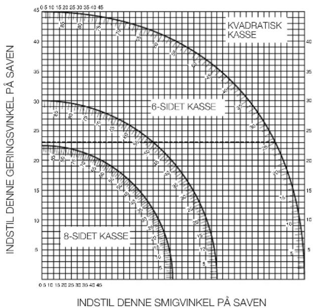
Compound litre (fig. P1 & P2)
This cut is a combination of a litre and a bevel cut. This is the type of cut used to make frames or boxes with slanting sides like the one shown in fig. P1.

If the cutting angle varies from cut to cut, check that the bevel clamp handle and the metre clamping knob are securely tightened. These must be tightened after making any changes in bevel or metre.
- The chart shown below will assist you in selecting the proper bevel and litre settings for common compound litre cuts. To use the chart, select the desired angle "A" (fig. P2) of your project and locate that angle on the appropriate arc in the chart. From that point follow the chart straight down to find the correct bevel angle and straight across to find the correct litre angle.
- Set your saw to the prescribed angles and make a few trial cuts.
Practice fitting the cut pieces together.
Example: To make a 4 sided box with 30 exterior angles (angle "A", fig. P2), use the upper right arc. Find 30 on the arc scale.
- Follow the horizontal intersecting line to either side to get the mitre angle setting on the saw (23^) .
- Likewise follow the vertical intersecting line to the top or bottom to get the bevel angle setting on the saw (40^) .
- Always try cuts on a few scrap pieces of wood to verify the settings on the saw.
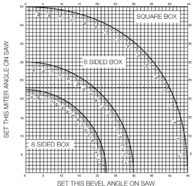

Never exceed the compound litre limits of 45^ bevel with 45^ left or right litre.
Clamping the workpiece (fig. A3)
Always use a material clamp when cutting non-ferrous metals.
- In most cases, the action of the blade is sufficient to hold the material firmly against the fence.
- If the material has a tendency to lift or come forward from the fence, preferably use the optional material clamp (28).
Sawing short workpieces (fig. A4)
It is advisable to use the length stop for short workpieces (32) both for batch sawing and for short individual workpieces of different lengths. The length stop can only be used in conjunction with a pair of optional guide rails (26).
Sawing long workpieces (fig. A3)

Always support long workpieces.
Figure A3 shows the ideal configuration for sawing long workpieces when the saw is used free-standing (all items available as an option).
These items (except the legstand and the material clamp) are required both on the infeed and the outfeed side:
Using the roller table (fig. A3 & A5)
The roller table (33) makes the handling of large and long pieces of wood very easy (fig. A5). It can be connected either to the left or to the right of the machine. The roller table requires the use of the optional legstand (fig. A3).

Assemble the roller table following the instructions supplied with the legstand.
- Replace the short support bars provided with the legstand with the irregular rails from the table on the side the table is to be used.
- Follow all instructions provided with the roller table.
Range of saw blades available (recommended blades)
Tungsten carbide Application Diameter Teeth tipped (TCT)
Negative tooth For wood, boards 216 24 rake thick-walled plastic profiles
For high-quality panels 216 48
(finer cut), thin-walled
plastic profiles
Negative rake For thin-walled plastic 216 60
flat-topped teeth profiles (e.g. window
blind slats, cable ducts)
When cutting non-ferrous metals, the machine is only to be used to perform vertical straight and metre cross-cuts in the metre saw mode. We recommend that bevel and compound metre cuts should not be performed in non-ferrous metals. The machine is not to be used for cutting ferrous metals.
Always use a material clamp when cutting non-ferrous metals. Make sure that the workpiece is clamped securely.
- Only apply saw blades that are qualified for cutting non-ferrous metals.
- When using lubricants, only apply wax or separation spray. Do not use emulsions or similar fluids.
- Connect an FI or DI switch between machine and mains to avoid residual risks caused by metal swarf.
The FI switch should comply with the following specifications:
rated voltage 230 V
rated current 16 A
reaction time < 15 ms
fusing current 30mA
The DI switch should comply with the following specifications:
DIN VDE 0661
rated voltage 230 V
rated current 16 A
fusing current 30mA
all-pole cutoff L+N+PE
PE monitoring
low-voltage release
Consult your dealer for further information on the appropriate accessories.
Transporting (fig. A1 & A2)
To transport the saw, set the bevel and mitre positions to 0^
- Press the combined lower guard and head lock up release lever (2) (fig. A1).
- Press the head down and press the lock down button (22) (fig. A2).
- Bring the saw blade to rest position and press the traverse lock (17).
Always use the carrying handle (3) to transport the saw.
Maintenance
Your DeWALT Power Tool has been designed to operate over a long period of time with a minimum of maintenance. Continuous satisfactory operation depends upon proper tool care and regular cleaning.

Lubrication
Your Power Tool requires no additional lubrication.

Cleaning
Keep the ventilation slots clear and regularly clean the housing with a soft cloth.

Take your tool to an authorized DWALT repair agent where it will be disposed of in an environmentally safe way.
GUARANTEE
30 DAY NO RISK SATISFACTION GUARANTEE
If you are not completely satisfied with the performance of your DeWALT machine, simply return it within 30 days, complete as purchased, to a participating Dealer, or an authorized DeWALT repair agent, for a full refund or exchange. Proof of purchase must be produced.
- ONE YEAR FREE SERVICE CONTRACT
If you need maintenance or service for your DeWALT machine, in the 12 months following purchase, it will be undertaken free of charge at an authorized DeWALT repair agent. Proof of purchase must be produced. Includes labour and spare parts for Power Tools. Excludes accessories.
- ONE YEAR WARRANTY
If your D-WALT product becomes defective due to faulty materials or workmanship within 12 months from the date of purchase, we guarantee to replace all defective parts free of charge or, at our discretion, replace the unit free of charge provided that:
The product has not been misused.
- Repairs have not been attempted by unauthorized persons.
Proof of purchase date is produced.
This guarantee is offered as an extra benefit and is additional to consumers statutory rights.
For the location of your nearest authorized DeWALT repair agent, please use the appropriate telephone number on the back of this manual.
SIERRA TRANSVERSAL DE INGLETES DW701/DW707
Enhorabuena!
Director Engineering and Product Development
HorstGroβmann

L'emballage contient:
Director Engineering and Product Development Horst GroBmann

nominate stroom 16 A
nominate stroom 16 A
smeltstroom 30 mA
Director Engineering and Product Development Horst GroBmann

- 1 ARS FRI VEDLIKEHOLDSERVICE
Director Engineering and Product Development Horst GroBmann

DeWALT, Richard-Klinger-Straße 40, D-65510, Idstein, Alemanha
15 Tire as chaves de aperto
Director Engineering and Product Development
Horst GroBmann
X. fOJmaa
Director Engineering and Product Development Horst GroBmann

DeWALT, Richard-Klinger-Straße 40, D-65510, Idstein, Tyskland
Sakerhetsinstruktioner
△uθuvntc AvantuEπ Poiovtwv
Horst Großmann
X. fOpsmaa
DeWALT, Richard-Klinger-StraBe 40
16 XpnoiopoieTe to owto epyaaleio
H evdeevyn xpnoonoinan avapepetal ae autec tic onyiec xpoewc. Mn xpnoonoeite epyaia xaunnc ioxuoc n npootheke yia bapiec epyaioe. To epyaio oac th aaioupynoe enituxoepa kai aophaeotepa eav xpnoonointheta oupwva m Tnnpoaiypapec tou.
PpOoXn! ToOn npAn EApTmuWv npOoNkwv 000 kal npayatonoiOn spyaotwov nou dovuotwta otic odyie autcE ykuovkiuvo Tpauaiaou.
17 Mn xnpaiponoieire kaawia yia epyaoiec yia tic onoiec dev npooipicovai
Mny kpatate note to epyaaleio ano to kaawio tou kai npata To kalwio yia va byalete to epyaaleio ano tn npica. Ppootatueote To kalwio ano 0epuoteta, lai kai aixnpes ywiec.
18 Euvtneite Emea ta epyaia a
Aiatme ta epyaia oac koptpa ka kaapadote va eioe 0e
theva epyaote kalutepa kalopaoletpa.Akooutei Tc
ooyie ouvtnpoewc kai tnc unodieic yia tv alayn
Eapntmuw. Eeyxete TaTKa to kalwoio kai, oe nepintwn
BaaNC, dwe To yia enkeun OE stafo ouvtnpoeWC nou evai
Eouaidomevoc ano mV DeWALT. Eeyxete npiodka ta
kawbia eniunkvovnc kai avtkataotne Ta oe nepintwn BaaNc.
Aiatme Touc diakontc xpnoeoc oteyvouc kai povtote va
mynival aepwveoi ano laoi kai ypao.
19 EAYETE eAV TO epyaiao aC exe 6a6c
Pniv xnpoonnoeTe to epyaleio, eleyeTe to npoeekTia yia evexoevec ia va a i oTtOaUpyoNcOnwC npenl. EeyTe av ta kivtna hep nival oWoTa ouvdepeva kaluypaumoueva, avd evxouv onaKaupatia, aviv elal oWotau vapuolooyneva kai avnnpovttal oEc oluvhkeyta gnOtJLeiToupyia Tou epyaleiou. Ppoatautikakalmuata n aaaa EApntmuata nou exouv xaAaa npeneva enokueaovtal navtikaotavtaoupwva me tcs onyie xpnoeoc.
Mn xpnauonoiite To epyaieio ev o diakontnc ivai xaalauevo, KAI PPOVtiote yia tvv avtikataoTaan Tou ano Eouaootnevo 0tauoutnpnoeoc.
20 EnkeuaZeTa epyaleia oac eEouoiootnevo OaOuvtnpnoes
To nEeTpiK epyAeio oac nInpei touxovtec kavoe c aapalaeia. Ia Tn anopuykivduwvy ia To xpnt, tuxov EIOKEUEC npenla vekTeauovta anokaiotika ano EIOKO TEXVIKO.
Ipoo8eoi Kavoviaoi Apaehiaq yia dAonpiova