
MIC Hinged DCA - Surveillance Camera BOSCH - Free user manual and instructions
Find the device manual for free MIC Hinged DCA BOSCH in PDF.
| Product type | Surveillance camera |
| Brand | Bosch |
| Model | MIC Hinged DCA |
| Power supply | 24 VAC |
| Data interface | RS-485 and Ethernet RJ45 (Cat5e/Cat6) |
| Mounting type | Hinged large conduit adapter |
| Housing material | Stainless steel (bolts and washers) |
| Connectors | M25 cable gland and NPT 3/4" with adapter |
| Fastening | 4 stainless steel M8 x 30 mm hexagonal bolts |
| O-ring | 80 mm x 3 mm |
| Plug | M25 x 1.5 mm with O-ring |
| Required tools | Torx T25 screwdriver, wrench for M8, Phillips screwdriver |
| Main function | Video surveillance with easy installation thanks to the hinge |
| Electrical safety | Mandatory grounding (green wire) |
| Recommended grease | MOLYKOTE® 111 for main O-ring (optional) |
| Precautions | Avoid pinching cables, do not damage paint |
| Included parts | Quick installation guide |
| Usage | Outdoor (recommended) |
Frequently Asked Questions - MIC Hinged DCA BOSCH
User questions about MIC Hinged DCA BOSCH
0 question about this device. Answer the ones you know or ask your own.
Ask a new question about this device
Download the instructions for your Surveillance Camera in PDF format for free! Find your manual MIC Hinged DCA - BOSCH and take your electronic device back in hand. On this page are published all the documents necessary for the use of your device. MIC Hinged DCA by BOSCH.
USER MANUAL MIC Hinged DCA BOSCH
english Table of contents 5
1 Install a MIC7000 Camera on a Hinged DCA
The hinge feature allows installers to “hang” the MIC7000 camera temporarily during installation for easier connection of cables/wiring before final bolts are installed.
Parts List
| 1 MIC Hinged DCA (MIC-DCA-Hx) |
| 4 Stainless steel hex bolts, M8 x 30 |
| 4 Stainless steel plain washers, M8 |
| 1 O-ring, 80 mm x 3 mm |
| 1 conduit adapter (male M25 to female 3/4" NPT)(Available in specific regions only.) |
| 1 blanking plug, M25 x 1.5, with O-ring |
| 1 Quick Installation Guide |
Additional Tools Required
| 1 | Torx driver, T25, to loosen and tighten the hook bolts |
| 1 | Wrench/driver to secure M8 bolts (supplied) to mount the camera onto the DCA |
| 1 | Wrench/driver to secure user-supplied bolts (maximum M8 or 5/16” diameter) to mount the DCA to the mounting location |
| 1 | Phillips-head screwdriver to attach ground wire |
| * * | (Optional) MOLYKOTE® 111 grease [from Dow Corning] for primary O-ring |

Warning!
Ensure not to damage the paint on the housing of the camera or the mount.
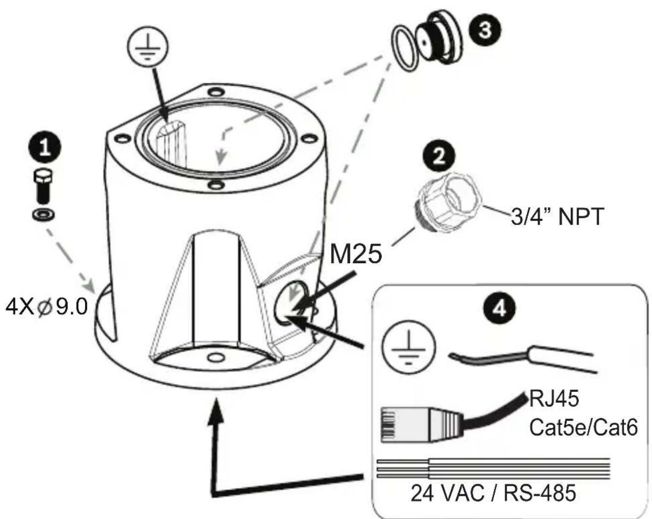
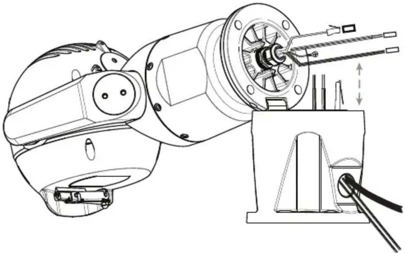
- Attach DCA to mounting location using user-supplied hardware (item 1). (Bosch recommends stainless steel bolts and washers.) Attach user-supplied conduit or glands to side or bottom hole. If applicable, use the supplied conduit adapter (male M25 to female 3/4 in. NPT) (item 2) if needed. Plug unused hole (item 3). Route cables into DCA (item 4).
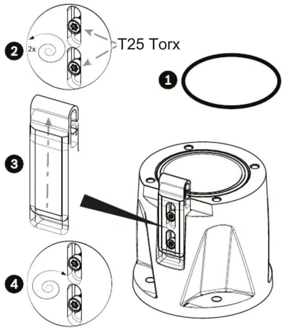
- Insert O-ring (item 1). Loosen Torx bolts two (2) turns (item 2). Slide hook up (item 3). Tighten bolts to hold hook in place temporarily (item 4).
natural_image
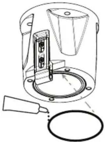
Technical line drawing of a mechanical device with a cylindrical component and a ring, showing no text or symbols.- For inverted installation, apply a small amount of grease to primary O-ring to hold it in place.

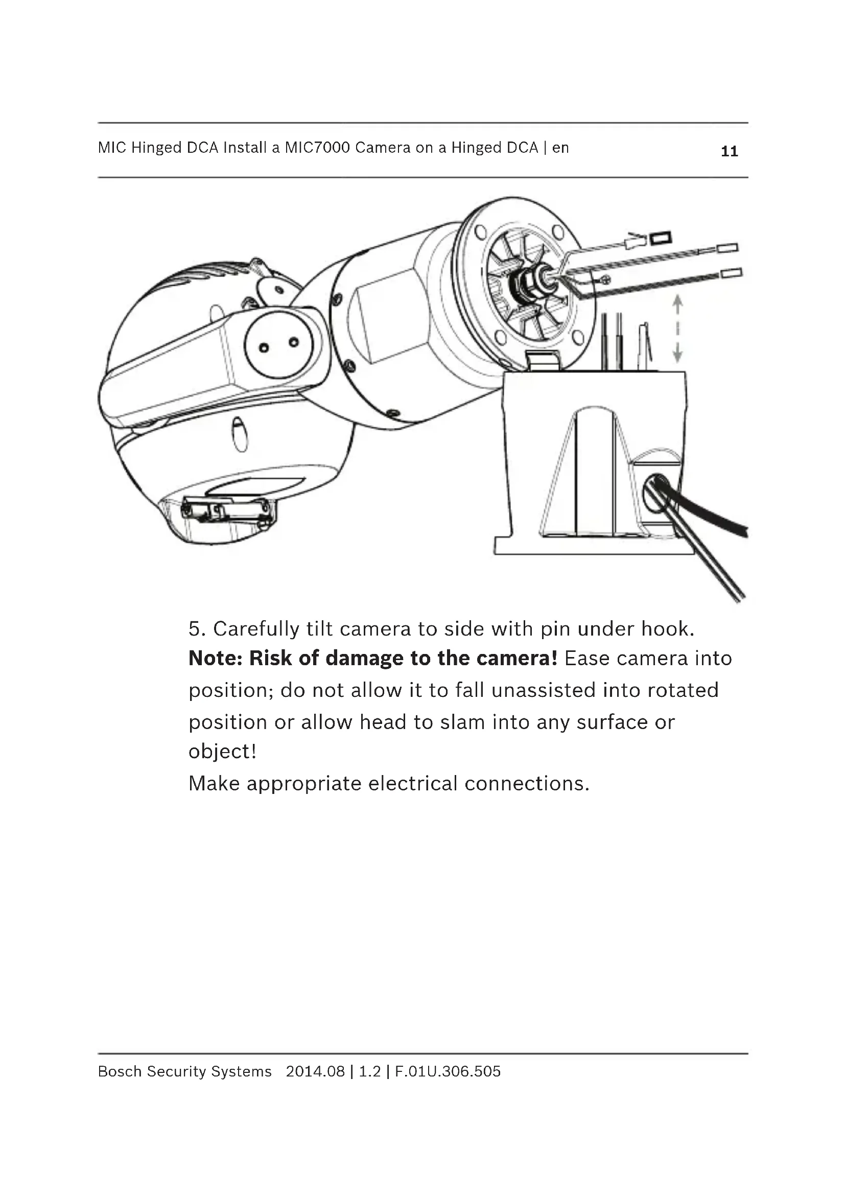
- Place wires into DCA while positioning base pin of camera under hook (item 1). Avoid pinching wires! (item 2). Slide hook down to secure camera pin. Fully tighten hook bolts (item 3).
natural_image
Technical line drawing of a mechanical assembly with no visible text or symbols- Carefully tilt camera to side with pin under hook.
Note: Risk of damage to the camera! Ease camera into position; do not allow it to fall unassisted into rotated position or allow head to slam into any surface or object!
Make appropriate electrical connections.
natural_image
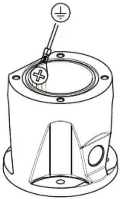
Technical line drawing of a mechanical component with a central hub and mounting holes (no text or symbols)- Screw green GND wire from camera base to ground hole on inside wall of DCA. If DCA is not mounted to earth grounded surface, attach user-supplied grounded wire (item 4 in step 1) to same connection point.

- Carefully tip camera to final position. Avoid pinching wires between camera base and DCA! Insert four washers and hex bolts (supplied).
natural_image
Technical line drawing of a mechanical device with a cylindrical component and a ring, no text or symbols presentnatural_image
Technical line drawing of a mechanical assembly with internal components and a close-up inset showing a tool interacting with a component (no text or symbols present)natural_image
Technical line drawing of a mechanical component with mounting holes and a central hub (no text or symbols)natural_image
Technical line drawing of a mechanical device with a cylindrical component and a ring, showing no text or symbols.natural_image
Technical line drawing of a mechanical assembly with no visible text or symbolsnatural_image
Technical line drawing of a mechanical component with mounting holes and a central shaft (no text or symbols)natural_image
Technical line drawing of a mechanical device with a cylindrical component and a ring, no text or symbols presentnatural_image
Technical line drawing of a mechanical assembly with no visible text or symbolsnatural_image
Technical line drawing of a mechanical component with mounting holes and a central hub (no text or symbols)natural_image
Technical line drawing of a mechanical device with a cylindrical component and a ring, showing no text or symbols.natural_image
Technical line drawing of a mechanical assembly with no visible text or symbolsnatural_image
Technical line drawing of a mechanical component with mounting holes and a central shaft (no text or symbols)natural_image
Technical line drawing of a mechanical device with a cylindrical component and a ring, showing no text or symbols.natural_image
Technical line drawing of a mechanical assembly with no visible text or symbolsnatural_image
Technical line drawing of a mechanical component with mounting holes and a central hub (no text or symbols)natural_image
Technical line drawing of a mechanical device with a cylindrical component and a ring, showing no text or symbols.natural_image
Technical line drawing of a mechanical assembly with no visible text or symbolsnatural_image
Technical line drawing of a mechanical component with mounting holes and a central hub (no text or symbols)natural_image
Technical line drawing of a mechanical device with a cylindrical component and a ring, no text or symbols presentnatural_image
Technical line drawing of a mechanical assembly with no visible text or symbolsnatural_image
Technical line drawing of a mechanical component with mounting holes and a central hub (no text or symbols)natural_image
Technical line drawing of a mechanical device with a cylindrical component and a ring, no text or symbols presentnatural_image
Technical line drawing of a mechanical assembly with no visible text or symbolsnatural_image
Technical line drawing of a mechanical component with a central hub and mounting holes (no text or symbols)natural_image
Technical line drawing of a mechanical device with a cylindrical component and a ring, no text or symbols presentnatural_image
Technical line drawing of a mechanical assembly with no visible text or symbolsnatural_image
Technical line drawing of a mechanical component with mounting holes and a central hub (no text or symbols)natural_image
Technical line drawing of a mechanical device with a cylindrical component and a ring, showing no text or symbols.natural_image
Technical line drawing of a mechanical assembly with no visible text or symbolsnatural_image
Technical line drawing of a mechanical component with mounting holes and a central hub (no text or symbols)natural_image
Technical line drawing of a mechanical device with a cylindrical component and a ring, no text or symbols presentnatural_image
Technical line drawing of a mechanical assembly with no visible text or symbolsnatural_image
Technical line drawing of a mechanical component with mounting holes and a central shaft (no text or symbols)natural_image
Technical line drawing of a mechanical device with a cylindrical component and a ring, showing no text or symbols.natural_image
Technical line drawing of a mechanical assembly with no visible text or symbolsnatural_image
Technical line drawing of a mechanical component with mounting holes and a central shaft (no text or symbols)natural_image
Technical line drawing of a mechanical device with a cylindrical component and a ring, no text or symbols presentnatural_image
Technical line drawing of a mechanical assembly with no visible text or symbolsnatural_image
Technical line drawing of a mechanical component with mounting holes and a central hub (no text or symbols)natural_image
Technical line drawing of a mechanical device with a cylindrical component and a ring, no text or symbols presentnatural_image
Technical line drawing of a mechanical assembly with no visible text or symbolsnatural_image
Technical line drawing of a mechanical component with mounting holes and a central hub (no text or symbols)Bosch Security Systems, Inc.
850 Greenfield Road
Lancaster, PA, 17601
USA
www.boschsecurity.com
© Bosch Security Systems, Inc., 2014


Brand : BOSCH
Model : MIC Hinged DCA
Category : Surveillance Camera