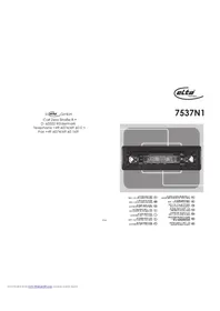
7173N2 - Car stereo ELTA - Free user manual and instructions
Find the device manual for free 7173N2 ELTA in PDF.
User questions about 7173N2 ELTA
0 question about this device. Answer the ones you know or ask your own.
Ask a new question about this device
Download the instructions for your Car stereo in PDF format for free! Find your manual 7173N2 - ELTA and take your electronic device back in hand. On this page are published all the documents necessary for the use of your device. 7173N2 by ELTA.
USER MANUAL 7173N2 ELTA
EINBAU IN DAS ARMATURENBRET
Vorsichtsmaßnahmen
AM (MW) 525 - 1615 kHz
FM (UKW) 87.5 - 108 MHz
Beware of small pieces and batteries, do not swallow them. It may be hazardous to your health and lead into suffocation. Please, Make sure to keep small devices and batteries out of the reach of children.

Important advice regarding hearing protection: Caution:
You care for your hearing, and so do we.
Therefore, use caution while using this appliance.
Our recommendation: Avoid high volumes.
Children should be supervised while using headphones; make sure that the appliance is not set to high volume
Caution!
High volumes may cause irreparable damage to children's ears.

NEVER let allow anyone, especially children, to put objects into the holes, slots or openings on this devise. This may lead into death due to electric shock. The device must only be opened by a qualified assistant.

Only use the appliance for its intended purpose.
This device may only be used in housings and business premises.

Please keep this instruction manual for further reference

Instructions on environment protection
Do not dispose of this product in the usual household garbage at the end of its life cycle; hand it over at a collection point for the recycling of electrical and electronic appliances. The symbol on the product, the instructions for use or the packing will inform about the methods for disposal.
The materials are recyclable as mentioned in its marking. By recycling, material recycling or other forms of re-utilization of old appliances, you are making an important contribution to protect our environment.
Please inquire at the community administration for the authorized disposal location.

Do not obstruct the ventilation of the device. Make sure, that no curtains, newspapers, furniture or any other type of object are blocking the ventilation system of the apparatus. The ventilation system must be clear of objects at all times! Overheating may lead into serious damage of the device and reduce its performance and lifespan.

Heat and warmth
Do not expose the appliance to direct sunlight. Make sure that the appliance is not subject to direct heat sources such as heaters or open fire. Make sure that the ventilation slots of the appliance are not covered.

Moisture and cleaning
This appliance is not waterproof! Do not immerse player in water. Do not allow player to come in contact with water. If water gets inside the player it may cause serious damage. Do not use cleaning agents that contain alcohol, ammonia, benzene or abrasives as these could damage the player. For cleaning, use a soft, moistened cloth.
SAFETY INSTRUCTIONS
- READ INSTRUCTIONS - All the safety and operating instructions should be read before the unit is operated.
- RETAIN INSTRUCTIONS - The safety and operating instruction should be retained for future reference.
- HEED WARNINGS - All warnings on the unit and in the operating instructions should be adhered to.
- FOLLOW INSTRUCTIONS - All operating instructions should be followed.
- VENTILATION - Openings in the device serve its proper ventilation, are necessary for the operation and prevent overheating. The unit should be situated so that its location or position does not interfere with its proper ventilation. Do not place on bed, sofa, rug or similar surface that may block the ventilation openings, in a built-in installation, such as a bookcase or cabinet that may impede the flow of air through the ventilation openings.
- HEAT - The unit should be situated away from heat sources such as radiators, stoves, or other appliances (including amplifiers) that produce heat.
- POWER SOURCE - The unit should be connected to power supply only of the type described in the operating instructions or as marked on the unit.
-
OBJECT AND LIQUID ENTRY - Care should be taken so that objects do not fall and liquids are not spilled into the enclosure through openings.
-
DAMAGE REQUIRING SERVICE - The unit should be serviced by qualified service personnel
a. The power-supply cord or plug has been damaged.
b. Objects have fallen into, or liquid has been spilled into the unit enclosure.
c. The unit has been exposed to rain or moisture.
d. The unit does not appear to operate normally. Only use the units and controls as described in this manual.
e. The unit has been dropped, or the enclosure damaged.
10. SERVICING - The user should not attempt to service the unit beyond that described in the user operating instructions. All other servicing should be referred to qualified service personnel.
11. CLEANING - Disconnect from mains power supply before cleaning. Do not use liquid or spray cleaners, only use a damp cloth. Follow the care and maintenance instructions in this manual.
12. LIGHTNING - During lightning and longer periods of non-use please disconnect from mains power supply and antenna.
13. SAFETY CHECK - After servicing the unit ask the customer service for a safety check.
14. OVERLOAD - To avoid fire and electric shock do not overload wall outlets and convenience
15. ELECTROSTATIC DISCHARGE - Disconnect from mains power supply and remove batteries if unit malfunctions. Reconnect after a short time.
IN-DASH MOUNTING
Precautions
After the wiring of all other connections connect the power wires.
The battery cable (RED) must be connected absolutely to the positive clamp (+) of the battery
To protect against short-circuits insulate all exposed wires/leads.
- After the installation secure all loose wires/leads.
Preparations
- Before the final installation of the unit first connect all wires and check if all connections were done correctly and the unit operates faultless.
- Disconnect the ground lead from the negative pole (-) of the battery.
- Select the mounting location where the unit will not interfere with the normal driving function of the driver and no danger for passengers during emergency braking exists.
- Consult your nearest dealer if the installation needs the drilling of holes or other modifications of the vehicle.
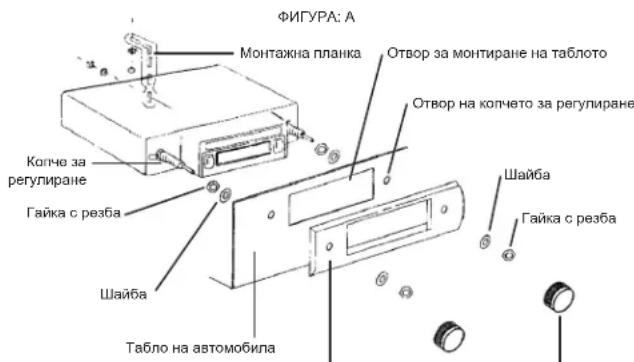
Mounting aperture
If a suitable mounting aperture in the dashboard is available, as shown in FIGURE A, the unit can be installed into the dashboard.
For such a mounting the dashboard should have a thickness from 4.5 to 6mm
Securing of the rear
Fix one end of the assembly strap to the roar of the unit and the other end at the protective wall or another, stable metallic part of the vehicle.
After the mounting the negative (-) battery clamp must be connected again.
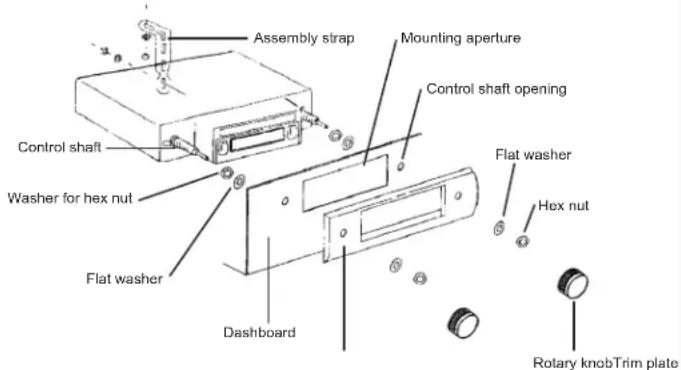
FIGURE A
WIRING
This unit is designed only for vehicles which operate on 12 V DC and negative ground electrical systems.
Exposed wires must be insulated absolutely in order to avoid a short-circuit between uncovered wires/leads and the vehicle body. Collect all wires as bundles and make sure that the ends of the wires do not have any contact with metal parts.
- Do not short circuit the antenna and ground wire.
This unit has a negative grounding. - Do not short circuit the speaker wires.
- Before the installation connect all wires and check the operation of the unit.
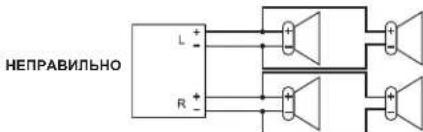
CONNECTION OF THE SPEAKERS
Precautions
- Must use only not grounded speakers.
The speakers used with this unit should have a sufficient music power rating. - Speakers with too low power rating can be damaged.
- Must use 4 - 8 Ω impedance speakers. A too high or to low impedance leads to performance losses and can damage of the speakers or this unit.
- Don't use a 3 leads speaker system with a common ground wire. Never connect the speaker wire at the car body.
- Keep the speaker wires away from the antenna and antenna wire (about 30 cm).
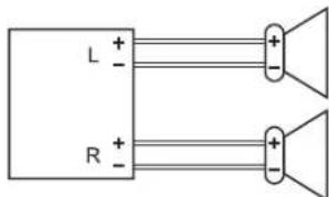
The unit becomes damaged, if speakers (front, rear) are not correctly connected.
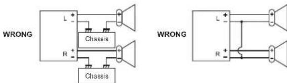
- Never connect more than one speaker to a set of speaker wires (except the connection of a tweeter).
Fuse
As a replacement for a blown fuse it is absolutely necessary to use a fuse with the prescribed rating (3 A). By the use of fuses with higher ratings or by the connection without the use of a fuse a fire or a damage of the unit can be caused. If the exchanged fuse is blown likewise, please contact the next workshop.
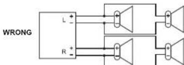
CONTROLS AND FUNCTIONS
1. ON / VOLUME
The ON / OFF switch and volume control are both operated with the left rotary knob.
Turn the knob a small section clockwise in order to switch on the unit.
By further turning to the right the volume will be increased and by a turning to the left it will be decreased.
2. POINTER FOR THE TUNED FREQUENCY
Displays on the frequency scale the actually adjusted frequency for FM (VHF) or AM (MW).
3. AM / FM (MW / VHF, SWITCHING OF THE BAND)
With the not-pushed button AM (MW) is activated. By pressing the button FM (VHF) is switched over.
4. TUNING
Adjust with the right rotary knob the desired station. The frequency indicator contains the scales for AM (MW) and FM (VHF). The desired station can be looked up by rotating of the knob to the right or to the left.
5. FF / EJ (FAST FORWARD AND EJECT)
By half push down of the button the mechanism is switched to the fast forward. By complete push down the cassette is ejected.
6. CASSETTE SLOT
Hold the cassette lengthwise and insert it into the slot to start the playback. (With the open side of the cassette showing to the right)
7. TAPE
During the playback of a cassette the green LED lights up.
8. RADIO
During the radio operation the red LED lights up.
OPERATION
Switching ON / OFF
Turn the left button a small section clockwise. With an inserted cassette the playback of the cassette starts at once and the TAPE LED lights up, otherwise the actually tuned radio station (dependant on the band) is played back and the RADIO LED lights up.
For switching off the unit turn the left button counter clockwise to the stop until it locks.
Note: When switching on the unit the yellow control cable to the automatic antenna is powered with +12V.
Volume control
After switching on the unit you can increase the volume by rotating of the left knob to the right (toward the label MAX) and decrease by rotating to the left (toward the label MIN).
Changing of the band and searching a radio station
With the not-pressed button AM and with the pressed button FM is activated. By rotating the right knob clockwise the frequency will be increased (UP) or counter clockwise it will be decreased (DN). The frequency of the adjusted station is shown on the corresponding frequency scale.
Inserting and playback of a cassette
Before inserting a cassette into the unit ensure that the tape is tautly coiled in the cassette. If not you can wind it up with the help of a ballpoint or similar and then insert the cassette as follows: Slide the cassette with the open side pointing to the right into the cassette slot. Press carefully on the cassette, until it is caught by the drive and loaded into the correct position inside of the unit. The TAPE LED lights up. The radio mode is switched off and the playback of the cassette starts automatically.
If the end of the cassette is reached, the cassette drive is switched off automatically and the unit switches to the radio mode (The RADIO LED lights up). The playback of the other side of the cassette can be done by turning around of the cassette.
Fast Forward
Press the button half down in order to fast forward the tape. A second gentle keystroke on FF / EJ activates again the normal playback of the cassette.
If you completely fast forward the tape, at the end of the tape the radio mode will be switched on automatically.
Ejecting the cassette
By pressing down the button FF / EJ completely the cassette in the cassette slot will be released. The radio mode will be activated.
Notes:
- The cassette remains in the slot if the power supply is interrupted during the playback of a cassette. If you turn on the unit again, the playback of the cassette will be continued.
- The cassettes should be always removed from the cassette slot if the unit is not used.
CARE
For cleaning wipe the exterior of unit with a soft cloth. Never use fuel, thiners or any other solvents.
TROUBLESHOOTING
To solve the common problems, read and follow the troubleshooting list. If you still cannot solve the problem, consult your nearest service dealer.
| Symptom Cause Solution | ||
| The unit cannot be switched on. | The fuse blown. Check the wires | for short-circuit and renew the fuse by a new one with same values. |
| The wire of the speaker touches the chassis of the vehicle or the like. | Wire or insulate the speaker wires correctly. | |
| No sound or to low volume. | The wires or the cable harness are not connected correctly. | Check the wire connections (see wiring). |
| Bad sound quality (distortions, interferences). | A speaker wire is short circuit by a screw. | Check the speaker wires. |
| The speakers are not correctly connected. | Connect the plus and negative poles of all speakers correctly. | |
| Bad radio reception. | The antenna is not pulled out. Pull out the antenna completely. | |
| The wire for powering the automatic antenna is not correctly connected. | Connect the wire correctly (see wiring). | |
TECHNICAL SPECIFICATIONS
1. RADIO
Frequency range AM/FM (MW/VHF)
AM (MW) 525 - 1615 kHz
FM (VHF) 87.5 - 108 MHz
2. CASSETTE DRIVE
Tape speed 4.75 cm/sec
Wow & Flutter less than 0.4%
Cassette mechanism auto stop
3. GENERAL
Voltage supply 12 Volt DC
Impedance of the speakers
Dimensions
Weight
4-8Ω
178 mm (W) x 110 mm (D) x 44 mm (H)
approx. 0.8kg
NOTE: SPECIFICATIONS ARE SUBJECT TO CHANGE WITHOUT NOTICE.
MODELL 7173N2 AUTORADIO AVEC LECTEUR CASSETTE
MANUELD'UTILISATION
INSTRUCTIONS RELATIVES À LA SECURITÉ
PLUS D'INFORMATIONS

AM (MW) 525 - 1615 kHz
FM (VHF) 87.5 - 108 MHz
2. LECTEUR CASSETTE
3. AM / FM (MW / VHF, A SAVOK VALTASA)
AM (MW) 525 - 1615 kHz
FM(VHF)87.5-108MHz
2. KAZETTA MEGHAJTó
Aunched in 1980, the Italian company was initially a small company that had been established by a group of scientists and engineers. The company was initially based in Rome, but it quickly evolved into a large-scale manufacturing business. In 1982, the company started to produce a variety of products including electronic devices, computers, and software. In 1983, the company expanded its operations to include information technology (IT) and software engineering.

AM (MW) 525-1615 kHz
FM (VHF) 87.5 - 108 MHz
2. IMPULSO CASSETTA
Velocà naslro 4.75 cm / sec
Wow & Flutter征求意见 0.4%
Rango de freuencya AM / FM (MW / VHF)
AM (MW) 525-1615 kHz
FM (VHF) 87.5 - 108 MHz
2. UNIDAD DE CINTA
LIGACAO DAS COLUMNAS
Precauçôes
3. AM / FM (MW / VHF, ALTERAR A ESTACAO)
AM (MW) 525 - 1615 kHz
FM (VHF) 87.5 - 108 MHz
2.LEITOR DE CASSETES
3. AM / FM (MW / VHF, WYBOR PASMA)
AM (MW) 525 - 1615 kHz
FM (VHF) 87.5 - 108 MHz
2. NAPED KASETY
Predkosc kasy 4.75 cm / sek
3. AM / FM (MW / VHF, BANDSCHAKELAAR)
AM (MW) 525 - 1615 kHz
FM (VHF) 87.5 - 108 MHz
2. CASSETTE DRIVE
Bandsnelheid 4.75 cm/sec
Wow & Flutter minder dan 0.4%
Cassette mechanism auto stop
3. ALGEMEEN
Voeding 12 Volt DC
MODELL 7173N2 KASET CALARLI OTO RADYOSU
KULLANIM KILAVUZU
EMNIYET TALIMATLARI
HARYCY BYLGYLER

AM (MW) 525 - 1615 kHz
FM (VHF) 87.5 - 108 MHz
2. KASET SÜRUCUSU
Suruucu Hiz 4.75 cm/s
Wow & silindir 0.4% den daha az
Kaset Mekanizmasi otomatik durma
3. GENEL
Elektrik gucu 12 Volt DC
Hoparfor Empedansi 4-8Ω
Boyutlar
Aagrlk
178 mm (W) x 110 mm (D) x 44 mm (H)
yaklasik 0.8 kg
NOT:ÖZELLIKLER ONCEDEN HABER VERILMEDEN DEGIŞTIRILEBILIR.
MODEL 7173N2 AUTORADIOS KAZETOVYM PREHRÁVACEM
NAVOD PRO OBSLUHU
BEZPECNOSTNI POKNY
DOPLNJUJICI INFORMACE

AM (MW) 525-1615 kHz
MANUAL CU INSTRUCTIUNI
INSTRUCTIUNI DE SIGURANTA
INFORMATII SUPLIMENTARE

Aveli grijla de componente de dimensionali mici si bateril, nu le inghiliti. Ele pot fi extrem de penculoase putand afectand grav sanalatea si sulocandu-va. Va rugam sa pastrati aceste componente si baterille除去 del accessul copilor.

3. AM / FM (MW / VHF, SCHIMBAREA BENZII)
Frecventa AM / FM (MW / VHF)
AM (MW) 525 - 1615 kHz
FM (VHF) 87.5 - 108 MHz
2.DRIVERUL CASETEI
Viteza casei 4.75 cm/sec.
Wow & Flutural mai putin de0.4%
Mecanismul casetei auto stop
3. GENERAL
Voltajul 12 Volti DC
Impedanta boxelor 4-8Ω
Dimensiunile, 178 mm (W) x 110 mm (D) x 44 mm (H)
Greutatea approxativ.0.8 kg
NOTA: SUBJECT CARE POATE SUPORTA SCHIMBARI FARA UN PREAVIZ ANTERIOR.
MODEJIb 7173N2 ABTOMOBINbHbI INPNEMHIK C KACCETHBIM IJEEPOM
PYKOBOIOCTBO NO 3KCNYYATAUIN
YKA3AHNIO TEXHNIKE 6E3ONACHOCTN
DAJIbHEIWARHFOOPMAU

OctepaTaeB HebOuHIN DetAne H Batape, He NoTAIe IN. 3o MoXET bbl onAHO DnA Bauero IIOPOBbI N OANeHb YUdbIe. ToKAIYCTA, PIMNITE Mebp, TcOsbI MaHBeHb NpObPb HApTeA XpHNHb B HeDocTyHOM DnE TetMe

BaxhblepekomeHdaun OTHoCInTeNbHOaunTbI cnyxa
Bb6epexkTe cboi CNYx, Ml ToXe.
NoTOMy 6ydyte octopoxhbl npn noB3oBAHN daHHbIM npBOpom.
HaapeKoMeHdaUa: N36eraIte 60nbou rpoMkoCTn.
DeTNdoJXHbI HaxoDHTcB NO npNCMOrPOM npN CNoJbOBAHH HayUHMKOB
ybeintecb, yTo ycTpoNCTBO He yCTaHOBnEHO Ha BbICOKn ypoBeHb rPoMkOCTN.
BHHMaHneI
Bolbua rpoMkoCTb MoKET npHHTb HENonpaHmbl yuepe6 cnyxTei.

HNIK04JDA Hnno38nJIHnHKOMO,OCo6BHeN DcETHM,CTABIHTb ppeIMTe b 8TBCPCTTH NINIeIe 3TOrIO PPbOBA. 3TOxMOTK pIPBECTN K CMEPTN BCNECTNBPOJAKHEH N3EKNTPUeCKHM TOKOM. OTKpBbA tPBn6OP MobON TToIbKO BKAINHIMPOBAAHH NMOIOHNK.

Mcnoj3yIe 3TOT np6Op TOnbKO no npedHa3HaueHNO.
3TOT npH6Op MoKet HcNoJIb3OaBtCra TOnIbKO B 6bITOBbIX NIN OΦnCHbIX NOMeueHmX.

XoAnyctnae, coxaHnne 37 y HcTpyKmIOI IaIaNHeIwero HcNOnI3ObaHnA B KaeCTBe crrpABOHTHkA.


Hnctpykunno 3aunTe okpykaoue cpebl
Ye HtIyIaIeYIbIaIaIeI npIbApB 8 KOJIcPcOxA cNk6bI bMeCte BcIbHMy 6bTbOBIMr OTOXdAMn; npeBaIeIe Ie BNYKT cIOpaI npeBaPbIXm IeNkTPKHOHbIX yCTPOBTr. CMBON HA npOdyKe, HcNTpyKm no IcNOIL3oBAHIno YINnIKAOBKA coDEpAIHnOFpAMlQIO nOcOIOE yTNIIaHaNae.
Maternepla bnoNekat pepeabotke, kak ykBa3Ano ha MapkoBpe. IbnAqadpa nepeba6TKe, TBNHOMHY MCN0L8OHN MATEpnaIbN NIN HINHM CNOOCBAm TYINNAUcN CTapbIX pInbOpOB Bbl OCSyIeTJIReTe BAKKb BkAIN B 3aunity OKyka2auCspdai.
KoanyanCTa, Y3nBae B ropockd oamHHCTpaqnnpaoNOKHeMe CHauHIOHNPOABHHxpyHKTOBYHnTHA3aun.

He npenrTCTayte BENTHUNPNPnnp60pa.5eBnTeCL,OTCnCTEMy BEHTNUNPNPbOpa He 3akpBnKoT3AHABECn,RA3aTH,MB6bnNnnpAIDmIbIKFOPOpyrTOINCACTEMA BENTHUNPNOTOCHOHN DOKHNb bblcBOBDHNO! PepePB MoKt npHEBcN K cepelEahm NpOBekdEHNM Pnnp60pa HCH3ITb Epo npO3BOIDTeJIbHOCTb I cPOCK cyhXb6.

Tenno BnaXhoctb
He nojaepraIte np6bop BOaeeCTBIO prrnMx COnHneHx nuY. Y6beITcB, yTO np6bOp He nojaepraTe BCAOeCTBIO XOToHHNK ToTnA, HAnPIMe, OOBpeBatenen INN OKPrTOrO IyO. YOToCTOBepTEc, YTO BeHTNIAIOHIIe ToBepTrpnaip6oHa 3KkBpIy

Bnara n oucnTka
IaHnnn I np6b HnOdohenpOnuBmbln! He norgykaTneep Bdy. He OpyckaiKoNTAKTcN Tpeep C BOiD. EcnBn BOaNaTe BHTyP Npeep, 30 MoXeT Nnoee cype3hBeNopekdeHnE. He nOtnb3yTe MOIOme cpeCTBa, copeKzAme AnfOKOrb, ammmak, 6OB3n lAnbAp43nBHe BceCTBa, NOCKONY OH MOrT JNOpeDnT Npeep. Dny OChTKn NpOy3yTeBcMKRN, yBNAXHEHN TKaHbO.
YKA3AHNIO TEXHNIKEBE3ONACHOCTN
1.BHIVMATENBHO IPOQHTNE IHCTPYKUN -BCEY K83AHHN NO TEXNHKKE 6E0NACHOCTN IN pyKOBOIcBO NO 3KcNNyatauIN DoJIKNbI bIbI pOCHATAHbI DO HauHana IcNObOBAHnycpOCTBA.
2. COXPAHANTHE HNCTCPYMIK - yka3aHnno YTeNaJIke 6eBaoJACoTHN IpyKOBdCTBO NO 3eknnyata NaIOnkHbI 6bItb CoxPAHEnBnI nIcPABKn B 6byDuem.
3. OSPAJIAMTE BHIMHAIME HE NIPYEYNIPKJDEHINBA BCE pIPOYPDKGIOHN HA KOPYCCA yCTPOCTBRA H BYKPOBDCTB NO kCNITYATAUON DOXTHKb BbTe PnHHTBa BO BHIMAHINE.
C. CNYDYE INCHYPKLMAH - BInONIHRAE BCE HANCAHIIIE HNCTPYKUNO NOCKTAYAANI.
5 BEHTNIUZIa - OTBERTPAB KOBPCYE yctPOTRBAc cnyHKAT DNEBTHINLAH OHN EOBXQDMJIb IINHOHPMANKHO PABObTIy CytPORCA, TAK KAPNDOTPAUBAOT ERO NPERpB. YCTPOTR3BO DOHNKO bIbI paCNOLOKHO TAKIM oBpACo, TIOBH ERO MECTONIOKGEHHE PnREPAITCTBOBANO EEO HOPMAHbIHO BENTHINLAH. He paCNOANARITE yctPOTR3BO HA KPOBAtI, DIAHBe, KOPE INIe DYTRN IONo6hIXe NOBEXHOCxI, INB A TAKNX MeCTAX KAK KHMKHNAONKIA INM WkAq, DE notOK 803Dxyupe3 OTBERTPAB BENTHINLAH BYETATZPDUHEN.
6. BbCKOKAR TEMEPATYPA - yCTPOIHTBO DOONHO paoonarabTcBdAaNOT hOHTHHIOB TnnaTBAK KAK paadatopb OTOHNEHKA, KYOHHe NITbI, HINpyxuY cTPOICTB (BkTHHAR YCINNTNA), KOTPBIE PNOABDHT BoHIOO KAIHCTBO Tnna
7. NCTOCHIK 3NEKTPONTAHIN -YCTPOCTBO DOJIKHO 6bTB NOJIKIOHEO TOLKIO K TAKOMY ITOCHIMKY INTAHNI, TNI KOTOPORO OINCAH B POKOBQCTBE NO AKCINYYATAUHN, NIKO YKAAN HA KOPNYCE YCTPOCTBA.
8. PINEMTBMyI JXIKIOCTK- CnQyTNeI0a3oBtNbC O TOM, YTObIbHa YcTPOCTBHe HnPadAaPaaJIHHe pIeMTbE, a B EOrOCTBeINHe NpOJIaBnIbHJXIOCTK.

- PEMOH'T NOBPEXDEHMH - yctpoCTBO NOIPOJNKT peMOHTy, BblIOHNREbIM
a. NpBpeKdHeHb UHPy MnBUNKa 3neKtponTAHm
b. BHytpkOpnyca yctpoiCTBa nonan nppeMeTb nnKkoctb
c.YCTPOHCTBO NOBBePrNoCb BO3DeICTBnIO DOxNn Bnarn
d. YcTPOCTBNO He yKTHUKNHUPyET HOPMAnbHO. HcNtONB3yIATE cYPTOCTBOH pEYrTAPoB TOnTOK Ta, KAK ONCAHO B HACTOTIeW PkyOBQCTBe.
e.YcTpaIcTbO bblno ypoHeHO, nI6o erO Kopnyc 6bln noBpeXdH.
10. TEXOBCTNYKMBAHNE - NOB3BOAEBH he DOJXHEN bHTATcBcO6yKNBtAB daHOHe YCPOICTBO CbIE TE O, 70 yk3aHO a HACTOEUM pyKObOCTBe No EKCNpyTAuHm.Bce DPTYBEHbO6yKNBAHNAO DNOXHb BnONHTbC kBNIAIPUPOBAHBM npEOCHONM
1NCTKA-Nepd Tm.KAK CYCHTHY cTYPCHBO.TOcoEOHHTIe EOT OHTcHnHA HNTAHHE. HNCIOB3yTEI DNEI YNCKTHX JIKDIE HIN AP303NJbHe MOOHUe CPECDTB.ANIOB3yTEI DNEI TOFO BNIAXHYBOETOO.BCnDEyTe COOTETCTBYOUIM YKSAaHIM, K3IOKoHNBM B DAHOM YKOBODCTBE.
12. P03A-80 BPEM R03H, A TOKBE B NEPOBdu NITENTB HNO NEPEPBBA 8 KCNPTAYUAM YCOTPCTBA, CNIYETQ OTKNIHbE ITO OTRNTNKKHA EIKIOTPNNTINNA ANDHTENHE
13. IPOBEPBA E6B3OACCHOTY UCTPOCTBA- Ncpe moPHToA/06CJyKKBAHNA YCTPOCTBA, NONOCITE CNYK8E PAOBJI C NKYNPATENMI NPOEPIITI 8eONATACCHOTY UCTPOCTBA.
14. NEPEPTPY3KA - 08 IsbHexane anoChOEt noKapa IIN npaXekHn 3eKPTPOKOM, He nepeykyaJIe MDAUHIOH cetb 3eKNTpOITAHNI.
15.3NKTPOCTATMHECKNI PAP3R--ECHYcTPOCTROH EyHKNDHPYET HOPMABTHO,OTCOEDMHNTe yctpoCTBO O TMOHTNHKA NIMAHKNE BATAPEKH. Upeea He6bIboupnpOMEXKYTOBPEHMH NOJDKIOHTHE 3NKTPOPTANIHIE CHOBA.
MOHTAX YCTPOINCTBA HA INBOPHOM INTKE
Mepbl npedocTopoKHOCTn
Ipo0oDa 3neKpOtnHAnHn CnEyET NOcOeINrHb T oBko NOcNe CoeINHeHn BEx COctaBbIX npOoD0B.
Ipo80 on 0 kAkyMylrtoHOB 6BapTeK (KPACHbI)OJIOKHN 6blBo cnoNIOKHTeHOB KEMMOk AkyMylrtoPA.
YTObI He NOyCTbTb KOpOTKoFO 3aMbKaHINr. CneJeT 3aNOnIOPOBaTb BCE OTKpUbIe YAcTHXn IPOBOIOB.
- Nocne yctahOBKn cneDyET noTAYHyB BCE CBNAOUIne npoBOda.
NoTobKa KycTaHOBKe
- Pered Tem, KAK OKOHATIELBO yCTAOHBtN 3a4HnKcIOBpA8T yTOCTPOBtO, CHANJAA bEEDITECb, TOA ACE PNOBADCoEOHHeH NpABINHbU, YIcPTORCTO HOPMAnJIbHO FyHKNUHOPIETy.
-OTcoeHNHTe 3a3emnHouu npoB0d OT OtpuataTebHO KnEMMbI (-) aKkyMyJrTopa.
Bb6epuTATEKMOCTAOJYCTAHOKM,IgEyCTPOINCTBOHeByETMeMaATBeIeCTBNAM BOITTEBAOBpEMe3bl,HIEbyETnpEDCTABnTbOnaCHOHTnPaNACCAKIMPOBBOBpEMA KKTIPHNHO TOPMOKEHNI. - U3HHTy e CBOEOT ABOTOMBnHbOro DInepra, HNYKHO NpOcBepRnBaTb DOONIHITbJIbHe 0TBePTCnI, INN Denatb KaKeTo-Dpynte MMeHNHEnB BHTyr ABOTOMNb
MOHTaXHbI npoem
Ecn HA np6b0PHOM uTKE eCTb CnueuHbHbl npoem dmo MOHTaKa yctpoiCTBa, KAK NOK3AHO HAPcMcyKHe A,ycrCTBMOXHOyCTAOHBt H np6bOpHM cTKe. TOnuHa np6bOPHOrO uTKe DOkHsCoCTaBn4,5-6 MM
HnKoHa He NoOoeDInHrTe 6Onene ODoHr PToMOKOrOBOpErIe K ODoHMy HAp60 nproBdoO (kPoMe CHyAee, eCInn NoOoeDHHrTe rPOMKOOBOpErIe DnR BepXHNxHCTOt).
PpeoOpaHnteB
IaamahbI cpoaeHro npdoxpaHHTe HEO6xoDMIO hnc013o8oatb npdoxpaHHTe TOnbKO pnpDnCnAHHO HOMHNHAE (3 A). Icno13o8aHBe npdoxpaHHTe 6OJIeB BcKcKOHO HOMHNHAE, nHcNpOJ3oBaHKe yctpoAChTa 8oo6be 6oe3 npdoxpaHHTe, moKet CTBe pnnmHO nokapa nnospeKdHeYr poCTBa. Ecn HOBbl npdoxpaHHTe Toke 6bIcTPO neperopen, o6oPHTBe B cnyk6y pemontA.
KHONKYNPABJIENH

1. ON / VOLUME
Ieaaepaauoaoaee KIOHNAI OINON3yTeTc TnBkIOUeHne H BkIOHKeHne yCTPOJCTBA, a TaKoe PeryuJIiueYPOB8rPOMKOHTN.
TtBbBnHtB yctpOCTBO, NOBepHATE KHONK HA OHO DeneHne NO YAcOB0 TcPENKE. TtBbY BeyNtBNr pOMKOTc, HNYKO NOBOPaMHBaTb KHONKY dAJIue BnAPBO, npi NOBOPoT KHNKKI BNIO, FNOOMKTy MynHbLIABTc.
2. YKA3ATEJIb HACTPANBAEMOYCACTOTbl
IokaBaAer TeKyuO uactoHa Wkane uactot FM (OBH) mN AM (CB).
3. AM / FM (NEPEKNIQUEHNE MEXKY ACTOTHBIMN DNANA3OHAMC CB/OBY)
Ecn KhoNkA OXTaBA, EcnBnBpoBaH dIaNa3oH cpeDHH BONH - AM (CB). EcnNnHaKATb KhoNkY, BKnIOaTeC HAna3oH FM (OBH).
4.TUNING
HaHnHyHIO pAdIOCTAIO C nOMOIO pyKn HAcTPOIK. INMkATOP cactOTU IMeET dIe shkanI nAI AM (CB) n FM (OBH) dAnaoHOB. CTAHIO MOXHO HAHT BpaAur pyKy hctPOnIK npBaO INn neBO.
5. FF / EJ (БыCTРАЕРМOTКВПЕPEDИ BыТАЛКИBAHAINE KACCEТbl)
EeNn HAKATb 3YKHOHNYHIOHNHY, HJIOHTOPRANKHm MEXAHnHM HANHT BbCTpyo nepemOTyBnepe.
Ecnna Haxatab KNONky nonHOCTbIO, KaccetA dydet BbToNkHyTa HApKy.
6.CNOTINRAKACCETbI
BCTABLTKE KACCTY B CTOT,CHbIbHAYtB BCPOPN3BDEEHNE. (OtKbIbCTOPHOA KACCTBY OINKHA 6BbIb NOBEPHYB NTPABQ)
7. TAPE
PnBocpon3eHmKaccTeIropnt3eHbC8oToHnO.
8. RADIO
Ecnpa6oatae paHNO,ropnt KpaChbI CBeToNDn.
PABOTA
BKnIOyHnE N BbIKIOyHnE
TneepHHTNE neybo HONky Ha oD heno Nne no cacoob O cnpoe. Ecnn octaBHeHa KACCetra,cp3ay
Ke HauHcTee e BocnpovaeHene, n aeroapTaC rbeToND TAPE,ecnn kaccetb HeT,TO
BkTHIOCTNc HAcTOpeHHA PAADNOCTAHU,naOgrrpTcCBtoND RADIO.
JrTO 10,TObBblKnHHTbYcTPOCTBO,NOBEPHTHE KONKNPOTMB YACOBI CTPEKNQ,DO KOHLA.
PnIMeAHmE: INp BkIOHcEHHH YcTPOCTBA HA KeENTb KaBeJIb ABtOMATWcckO hTeHHN NOaTcER +12B.
YpOBeHrpOMKoCTM
CnOe BKNKQEHN YcTPOJCTBA MOHO yBENHMTb POMKOCTb, NOBOPaHNBa NEBY KONKY BnPaBO (no HapnabNEHIO K OTMeKEMAX), NyMEHBaTb rPOMKoCTb, NOBOPaHNBa KNKNY BnEBO (no HapnabNEHIO K OTMeK MIN).
PepeknoueHm Mekdy dHaana3oHaMn Nnock paNoctaHm
EcnHKnKHa OKATA, PBOaTeT noAHIOAM, eCNHKnKHa KNAKTA, toAKNBEN dAAOON FM. EcnBpaATs pIbnyo KNO NocOBor CTpeKNE, cactota 6yDtET yEnWbHbATscn (UP), ECN BpaATs pOINTB NocOBor CTpeKNE, cactota 6yDtET yEmbHbATscn (DN). CACTORA HAIeHNHO PANDOCABTNp 6yDtET nKa3AHA HA COBTETCTBvUoJcUkane.
BcTaBka H Bocnpn3BeDeHHe Kaccetbl
NepeT Mek BCTABNTB C BYCPTOBKACCETY. NPOeBTE, YTO NHEKA NEPEMOTATA H33A. EcnI INHNAE HcNEPOPTATA, E6MOXHO NPEMOTATA C NOMOHTB KPYUN, KAPAHDAIIN HINDPYTOR NObDHoro PnepMeta, NOCE Yero BCTABNTB KACCETY cneDyouIM OBPASOM: BCTABTe KACCETY B CNOT A, TQb0E e ONkPTBA CTOPOA HUNa NoepBYTA BnPBO. CnERNA HADABITE HA KACCETY, OTB0E b 3AXRATNIENTOPTAOHKB MEXAHN3M, IN KACCCOTA BCTANA HA CBOE MECTO. 3AROpITCA BcTeODNID TAPE. PAnIO BbIKNOHTCA, IN BCOPON3BEHNEH KACCETB HAYHTCB ATOMATHECNIC.
EHNIOCTNHYT KOUEI KACCEThI KACCEThI NpBHOAD OTKNIHAEcTc AOTOMATHeCKN, N yCTPOJCTBO NEPEOXOH B EKIM PAHO. (3aRpaTeC TcBEOtOHOA RADI). 4TOb6 BOcnpOnsBeCTn DpyTuO CTOPHO KACCETU, ee HNYKO NEpeBepHTy.
Bbictpaepemotka Bnpe
YtBbI nepeMOTbI pNkHbEpe, HAMKIMX KHOHNHOIN. NIOPTOBH XAHATHE KHONFF EJ / ECHOB AKBTHBYET HOPMAHBOB BOCPOINB3BIDENB INKACCTNI.
EJINBBOBEMPEPMEOTKNBbNIOHCTbIOPEPOMAETe PIIENKHY,TOABTMATNECKBNKIOUHTCR EPKIMPAHO.
BbItaIKBaHnKacCeTbI
EcnHnKbHKNFF/JEINHOCTbIO,Kaccete6ydtBUTONHYaNcO7a,ncne 8ero 6ydet AKINIRPOBBH DOKM PAIDIO.
DpMeyaHn8:
- Ecnq BO BPEM BOCPN03BDEHNE npDanaet 3eKPTONPHTAHE, KACCETA OCTaER C bCNOT. Ecnq NpOaTbE 3eKPTONPHTAHE CHOA, BOCPN03BDEHNE 6yEDTnpO2nKHO.
Kaccety Bcerda cneyet BbHIMaTb nCnota,ecn yctpoCTBO He nCnon3yETCA.
05CJYKBAHNE
JIYI YICHTYCPTOCTBHA,IPOTPIE EHO BHLUHOOACTbMHKD BOToLIOHO.HNKOIaHE MCNIOBAyTEI JINI 3TO TONIOHO HJpyDTAE PACTBOPTEN.
YCTPAHENE HENCPABHOCTEIN
ДИЗЕРЕПЕЦВОМБОЧьнБИХОПОБЕСТЕ ВОЛТЕСТСКЕПИЕ NIXE BLY BC SEРNOH OMEKETY CYPANTHA PONPENEMY, OBPHTATNEB CB NXYKBY POMETA.
| Призник Причнaya Реценье | Pereropelen predoхсангь. ПорobельPrepoDA Ha налочи КОТКТО Замыкани. и заменITE Predoхсангь (TORO ЛС HOMHANAL). | |
| Роровд ромковогорител примаостя к сорус авTomоблия по дутую metallinechki част. | ПорбедиитelPrepoDA правильно, по заимларутей ИX. | |
| Нот зува ил зув Служков ТИХИ. | Поровд пос"Doдинэнbl нерравильно. | РоровельPrepoDA соевения (CM, раддд) «Соевени�PrepoDAOB». |
| ПлобODE Канес硐о зува (Искажения, поэн). | Поровд ромковогорител зakopoун винTom. | РоровельPrepoDA ромковогорител. |
| Громковогорител пдддддддддддддддддддддддддддддддддддддддддддддддддддддддддддддддддддддддддддддддддддддддддддддддддддд徳. | ПлобODEпс пс пс пс пс пс пс пс пс пс пс пс пс пс пс пс пс пс пс пс пс пс пс пс пс пс пс пс пс пс пс пс пс пс П П П П П П П П П П П П П П П П П П П П П П П П П П П П П П П П П П П П П П П П П П П П П П П П П П P P P P P P P P P P P P P P P P P P P P P P P P P P P P P P P P P P P P P P P P P P P P P P P P P P R R R R R R R R R R R R R R R R R R R R R R R R R R R R R R R R R R R R R R R R R R R R R R R R R R P P P P P P P P P P P P P P P P P P P P P P P P P P P P P P P P P P P P P P P P P P P P P P P P P F F F F F F F F F F F F F F F F F F F F F F F F F F F F F F F F F F F F F F F F F F F F F F F F F F P P P P P P P P P P P P P P P P P P P P P P P P P P P P P P P P P P P P P P P P P P P P P P P P P S S S S S S S S S S S S S S S S S S S S S S S S S S S S S S S S S S S S S S S S S S S S S S S S S S P P P P P P P P P P P P P P P P P P P P P P P P P P P P P P P P P P P P P P P P P P P P P P P P P T T T T T T T T T T T T T T T T T T T T T T T T T T T T T T T T T T T T T T T T T T T T T T T T T T P P P P P P P P P P P P P P P P P P P P P P P P P P P P P P P P P P P P P P P P P P P P P P P P P C C C C C C C C C C C C C C C C C C C C C C C C C C C C C C C C C C C C C C C C C C C C C C C C C C P P P P P P P P P P P P P P P P P P P P P P P P P P P P P P P P P P P P P P P P P P P P P P P P P p p p p p p p p p p p p p p p p p p p p p p p p p p p p p p p p p p p p p p p p p p p p p p p p p p P P P P P P P P P P P P P P P P P P P P P P P P P P P P P P P P P P P P P P P P P P P P P P P P P L L L L L L L L L L L L L L L L L L L L L L L L L L L L L L L L L L L L L L L L L L L L L L L L L L P P P P P P P P P P P P P P P P P P P P P P P P P P P P P P P P P P P P P P P P P P P P P P P P P M M M M M M M M M M M M M M M M M M M M M M M M M M M M M M M M M M M M M M M M M M M M M M M M M M N N N N N N N N N N N N N N N N N N N N N N N N N N N N N N N N N N N N N N N N N N N N N N N N N N M M M M M M M M M M M M M M M M M M M M M M M M M M M M M M M M M M M M M M M M M M M M M M M M M P P P P P P P P P P P P P P P P P P P P P P P P P P P P P P P P P P P P P P P P P P P P P P P P P N N N N N N N N N N N N N N N N N N N N N N N N N N N N N N N N N N N N N N N N N N N N N N N N N P P P P P P P P P P P P P P P P P P P P P P P P P P P P P P P P P P P P P P P P P P P P P P P P P E E E E E E E E E E E E E E E E E E E E E E E E E E E E E E E E E E E E E E E E E E E E E E E E E E E E E E E E E E E E E E E E E E E E E E E E E E E E E E E E E E E E E E E E E E E E E E E E E E E E F F F F F F F F F F F F F F F F F F F F F F F F F F F F F F F F F F F F F F F F F F F F F F F F F F |
CNEUINΦUKALNA
1.PADNO
JAMANOHAM/FM(CB/OBH) AMCB525-1615kF
FM (OBU) 87,5-108 M
2. KACCETHbI INPbBOd
CKPOGCTBAMXHEHNN4.75cmC
DEToHauNnDPOXAHMeHee0.4%
JeHTOpTApKbHmMexaHn3m ABTOCTOn
3. OBUA YACTb
3NeKTPoNTaHHe 12B, NOCToHHbI TOK
IMnepaHc rpoMkoBopHTeNe 4-8Ω
Pa3MePb
HCTAINPAHE B TABIOTO HA ABTOMOIBNA
PpeynpexdeHn
Cne Cbbp3BaHTo HA BCnKn Dpyn Ka6en, CbpxTe N Ka6enNte Ha 3axpaHbAHeTO.
KaBeBtNa hkyMmYnatora(UEPBHE),Tp6Ba Da 6Be daCbaPaaH cama KkM noNOKHTeINHRT nnoKc(+)Ha hkyMmYnatora
3a da npedna3nTe ot KbcocbeDHeHne, H3OInpaTte BCNKn Oronen Ka6eHNHaKpaHHn.
CneiHCTaHpaHeTo,3akpenTe HeNoDbXKnHO BCnKxnaabn KaBeHHaKpaHnU.
NoroToBka
- PteiHnCHaIaHetaHO tycpOHTBTO, mPbO CaPpKEt eChHKn KabEn n npopeBete daN C a853a3HH papanHHN, cneT Ota npoBeBete n yctpOHTBTO daN paabo TB 363 npo6Hen
- OTKaayTe 3a3eMaBaaHrT KaBEn OT OTPuataHnHrT NIOc (-) Ha akymyNaTopa.
Vi6epeTe MRCTo 3a MOHTIAPHe, KbEToCHYTOPTOBOHrMAHaI pNepHn HAOPMHOHIOUdHApHE BAHOJIaH NMRDA a cIIOA h2 tINHNTBE C bNHYA HBA03NHO CH
Cb5p9eTe c nHb6n3K4nDmIpy hA bTOMoBnBnBA H, AOKHcTnAaJTHaIaIbIaIbKa 0nOoBHaHTo HbDyNnHnDyNpOmoEHnB aBTOMOBnHa.
MOHTaXHHN3NCKBaHn
AkoB7aHbAMoNIMHaNOxOxOyUcNOyBaMOHTax,KaTOeNOKaHO HΦIYPA A, YcPOTHBOTOMOKe Da 6bDe INCTANpAOHO.
PnTakbMOHTaK,de6enHataHa Ta6noTo Tpa6Ba Da 6bHe No-TbHKa ot 4.5 do 6 mm
Cta6nnn3npaHe Ha 3aHaTa Yact
ПИКЕDEDET eMHN KPAI H MOTAXHATA PANAHA KM 3AEDHNA KPAI H A CTPOYBTO, A DYPYNRT KM I PNDaTHA CTEH N IN DYTA CStbNHMA METAHNA ACT qad TBNOTA H ABTOMOHNIA.
Cne moHTaxa OtpauateHnna nonIOc (-) Ha akymyataopa Tp8Ba da ce Cbpxe OTHOBO.
Koneta 3a BbptHeIpeDeH na
OKABEJIYBAHE(CBbP3BAHE)
TobaYCTPBOE EIOPOEHPAHO 38 ATOMOBUNKOTO PA60T H 12 V npAB TOH IMAT OTPUMLNEH3B0D 38 3AHYNPABE.
BCHN KABENI TPR68a 7a 6bDat NIOIMHAN MHORO D06pe C cae Hc b3eHRe Hc b2dHHeMH MEXy Hn30HnPAH Nc HApKaHnHn IN KOpnyCa HABOTMOHN. Cb6paHTe BCHN KABENI Hc HONOBc Hc YEbpete, Ye HApKaHnTcHMe IM He KOHTAryBtC dpyrM MeTHAnqCTH.
PABOTACYCTPOINCTBOTO
BKNIOUBAHEN3KNIIOVAHe (ON/OFF)
3abptre NBOO KOTHE MANKO NO NOCOA HA WBCOBHKOBATA CTPEKNA. AKo HMA KACETKB A KACETOHO, TR ATOMATHNO 3e 3aONOO BbAPOB3EgDAH e 3aNHCIA CBTNIHHRT CTHINH 3a pa60ta HkaceToTHA TEAPTEc Ce kBIOH. AKo HMA NoCTABHO KACETPA, Pa60toCe BIKIOVA H TekyUata padoNTAOHUN (B 3aBICMOCT OT i6bPAHITe BbHN). 3aONBA da pa60tN KATO CBTBa CBTNIHHRT CTHIN Radio.
3aJaHbNHTePAJIOHO,3aBbTBeTcIHIOTO KOITHO OboPaTHo HA NACOBHKOIBORA tCPENKIA,doKATO CnPE Hc2AKNIHHeNOBdIKHO.
BeneKka: Korato yctpoCTBOTo CE BkIOHn, KbIITnAT KAbE n KbM ABOTMAHTHATA aHTHeA ce 3aXpaHBa C +12V.
HactpoKaHa3Byka
CnBkIbHbA HbYcTbHTo, KOtOe Ta yBaERNTHte 38Kb, Ka 3aBbPntHe IaBOTe KOHHe HADCHO (Km HADNCA MAX) r Ho HAMBAbe, Kato r bLpNTHe HANBo (kM hADNCA MIN).
PpOMHa Ha BbHHTe N TbpceHe Ha paAdnOCTaHua
KORATO KHOTETO H E HATINCHATO, PAHOI TO AOBHTO H CpeDHN BILHNN (AM), KORATO E HATINCHATO, PAHOI H A KCB N BILHNN (FM). KORATO BPTHTE ADOHCHO TONE NO Y COASOHIKKOATA CTPEKNIA.
YecTOTHTe Ce nokuHAT (UP).Mn o6pTaHO Ha YacOBHmKoRaTc cTePikKa - HAMANBaT (DN). YecToTata Ha N3bpaHATA CTAnuCe BvKDa HA CkAaTA Bbpy KOrTo ca 1nnncanr paNIOBbHnTE N YecTOTHTe.
Noctabhe npocnywbahe Ha kaceTka
Ipei Da bKapate kacetka a yctpoctboto, ybpete ce, ye nhtata e npaHnHO HABHTa n onhata. Ako he B, meoKte da aonbHeTc n oomCtHa HA MMKnA KIN MOnMn Hocne da bKapate kacetkata kaktO cncBDA
Bkaparite KacetKata C bOpTeHATA cTpaC h NcHTATA Da cOnHn HAdrHO B oTaRopa 3a KacetKata.
HATChene KacetKata BNMMATEHO,doXATO ce NOE Me TcOyPTCBTOHO 3e 3ApedBO B npAByINo
NO3N3a 3bNoP03BeKJDAe, BeHana CBETBA cINHbT TAPE.PaIIOHO CE 3KnIOHbS a
ABOTMATHIO 3ANOVA 3bNoP03BeKJDAe HAKcKTATA.
Korato 3aHbHt HA KACETKATA 3abBpuu, KACEToDPOHt CE tKIOKnOBA BABOMATnHO H pEmmHBBA B Pekm HAO (cSeTNIHNHt CNHAN RADIe C EKIOHNA. BApOnsBeXaHDoTe Ha o6pHaTHaCTa PHA HA KACETKATA MOE DA tCAHe KO TA r OeOBhne OTOpyrta CTPAH a OTHOBO cPbXHE a KACEToDPOHA.
БьрзнанpeД
HATCHNE KOHOTEN HANOLOBINA, 3a da npbEbPHTAE KACETKATA 6b3PO HANPEI. HATCHNE TEKO OHBOH KOHOTF F/EJ, 3a da ansohe HTHO BOHO HOPMAHO Bb3PNOBEXBAKDA HA KACETKA. AKO INKATE HA NIO da npheABHnEe NEHTA, 3a4pBkTe DO KAPI HA KACETKA, KORATO PAHIMO TIE CO BKNHOH ABMTMTHNHO.
N3BaXkaHe Ha KaCeTKaTa
Kato ce HATNHCNE KOHTF.EJ HanbIHO, KACETKATA ue Ie Ie Nte OE yctpOCTAO.ToRaA BATEMATOHc 6e AKTBIPA dao peKHHa
Benexkx:
Korato aaxpaHbAeTO Co npkckno NO Bpme HA bIaPn3B6XdHae HA KACoTKata, Tg Ucctane H BacetofoHa. Korato BkIOHte YcTPOCTBOTo OTHO, B3PON3EaHHe To HA KACeTKata Ue npDfNk
Kacetkata Tpr6Ba BHHa n Da e N3BaHeHa OT YCTPOHCTBOTO, AKO HMa Da CE NHNON3Ba.
PNUKNIPOIDPbKA
3aJaHOHTMIE,NTHnPJIeIOBNEbPHXOCTTA HAYCPOCTBTO C MEKIA KHPNA.HNKORA HN3I0N3BAIETROPAHXAHHNECKPEAETBNI INNOPODNI BAPTRIOH.
NPOBEMM N TAXHOTPEWEHNE
3a da peunite obkHobene npo6nemnpoYeTe n cIeBaa TcNcBka c npo6nemnTRXHTOpeuHne.Ako Bce naKHe moKeTe da ce npaBte c npo6nema, KOChyTnpaiaTe ce hai bNik3Knaepb3nuehcpntb a haunite npoDyKTn.
| СимпTom Пricунна Рейhoe | ||
| Устристов по се в典型案例. | Пrelд�аителя e наогорл. Пробerte Kaбелite за Кьсо CBдинени и Смehete пrelд�аителя с Нов от сьцата сюност. | |
| Кабел на говорител огира до коруca на豌омobида яни насыдце Има "Кьсо CBдинени". | Свржete яни на олларайе Кабелite на говорителite равлино. | |
| Нама зык яни e Тьрдөнөдүхь. | Кабелite яни снolangовете от Кабели не са CBрзани равлино. | Проберete връдени на Кабелite (ВИХт "Одбелаян"). |
| Почи Качалстов на зыka (преьсвaning, сMuшени). | Кабел на говорител e сыран "На Кьсо"от ВИNT. | Проберete Kaбелite на равлино. |
| 「Товорителite» He ca CBрзани равлино. | Свржete плосоветe и Мннсүte на BCчн равлино. | |
| Поч радиocинал. | Аntechа差别 He e разиьнata. Раш. | Нote污染防治н. Свржete Kaбелite равлино (ВИХт "Одбелаян"). |
| Кабелite за зхрахвае на豌омotivчнatable спета He ca сырдани равлино. | ||
TEXHNUECKX XAPAKTEPNCIKN
1.PAHO
Cectoteh 6x8at AM / FM (MW/VHF) AM (MW) 525-1615 kHz FM (VHF) 87.5-108 MHz
2. KACETOΦOH
CKPOCT HA HENTATA 4.75 cm / cek.
HeycTOMHBOCT HA TOHA N KONEBAHNA NO-MANKO OT 0.4%
KaceTeH MEXAHINB MB ATCTON
3. OBUN
3axpaahane 12 BOITa npab TOK CbIPOTHINIEHME Ha roBOPTEJIte PAmepn Terno
4-8Ω
178 MM (UHPOHHa) X 110 MM (bIJIHHa) X
44 MM (BICOHHa)
πριδπιθετινηθο 0.8 K
SEJIEKKKA: XAPAKTEPNCKITE MOFAT DA CE POMEHRT BE3 NPEyIPEKDEHNE.