
S3EXQL - Pregnant PIONEER - Free user manual and instructions
Find the device manual for free S3EXQL PIONEER in PDF.
| Product type | 3-way bass-reflex floorstanding speaker |
| Brand | PIONEER |
| Model | S3EXQL |
| Configuration | 3-way |
| Speakers | 2x 16 cm woofers (aramid/carbon cone), 14 cm midrange (magnesium alloy), 3 cm tweeter (ceramic graphite) |
| Nominal impedance | 6 Ω |
| Frequency response | 20 Hz to 100 kHz |
| Sensitivity | 88.5 dB (2.83 V) |
| Maximum input power | 160 W |
| Dimensions (W x H x D) | 350 x 1224 x 541 mm |
| Weight | 48 kg |
| Magnetic shielding | Yes |
| Cabinet material | Solid MDF (thickness up to 100 mm) |
| Main technologies | CST coaxial, ceramic graphite diaphragm, magnesium alloy, aramid/carbon composite, LDMC magnetic circuit |
| Supplied accessories | Decoupling bases (3), cork shims (3 types, 2 each), anti-tip attachment, screws, grille, instruction manual |
| Connections | Gold-plated terminals, compatible with bi-wiring and bi-amping, straps supplied |
| Maintenance | Clean with a dry cloth or diluted mild detergent; do not use thinner or benzene |
| Safety | Do not place at height, avoid falls, do not overload the amplifier, use the anti-tip attachment |
| Installation | Rests on 3 points with adjustable rear decoupling spike; use cork shims to stabilize |
| Recommended use | With amplifier 4 Ω to 16 Ω, large gauge cables of minimum length |
Frequently Asked Questions - S3EXQL PIONEER
User questions about S3EXQL PIONEER
0 question about this device. Answer the ones you know or ask your own.
Ask a new question about this device
Download the instructions for your Pregnant in PDF format for free! Find your manual S3EXQL - PIONEER and take your electronic device back in hand. On this page are published all the documents necessary for the use of your device. S3EXQL by PIONEER.
USER MANUAL S3EXQL PIONEER
Pioneer sound.vision.soul
S-3EX
Speaker System / Enceintes acoustiques / Lautsprechersystem /
Sistema di diffusori / Luidsprekersystem / Sistema de Colunas /
Sistema de colunas / Hogtalarsystem / Hojttalersystem /
Hoyttalersystem / Kaiutinjarjestelma / Akyctuieckar cnctema
Discover the benefits of registering your product online at http://www.pioneer.uk (or http://www.pioneer.eu)
Décovrez les nombreux avantages offerts en enregistrant votre produit en ligne maintainant sur http://www.pioneer.fr (ou http://www.pioneer.eu).
Bitte nutzen Sie die Möglichkeit zur Registrierung hres Produktes unter http://www.pioneer.de (oder http://www.pioneer.eu)
Registra il suo prodotto su http://www.pioneer.it (o http://www.pioneer.eu) e scopri subito quali vantagei puii ottener!)
Ontdek nu de Voorden van online registratie! Registreeuw Pioneer product via http://www.pioneer.nl - http://www.pioneer.be (of http://www.pioneer.eu)
Registre su produto en http://www.pioneer.es (o en http://www.pioneer.eu) Descubra los beneficios de registrarse on-line:
Registe o seu produto em http://www.pioneer.pt (ou em http://www.pioneer.eu). Descubra asvantagens de o fazer ahora on-line.
Registrera din produit pa http://www.pioneer.se(eller pa http://www.pioneer.eu). Upptack fordelarna med att gora det on-line nu.
Registrar dit produit pa http://www.pioneer.dk (eller http://www.pioneer.eu). Opiev fordelene ved at gà online nu.
Registrar produit ditt pa http://www.pioneer.no (http://www.pioneer.eu). Oppdag fordelene med dette p a nettiet i dag.
Rekisteroi tuote sivustossa http://www.pioneer.fi (or http://www.pioneer.eu). Tutustu nyt online-rekisteroi tymisen etuihin.
3apernctpuyite Basse ndenne Ha http://www.pioneer-rus.ru (nni http://www.pioneer.eu). O3hakombtecsb c npemmyeictbami peimctaumn B INHTepHET
Operating Instructions / Mode d'emploi / Bedienungsanleitung / Istruzioni di utilizzo / Handleiding / Manual de instrucciones / Manual de instruções / Bruksanvising / Brugsanvising / Bruksanvising / Käytöohjeet / Incrtykuni no 3Kcnnyatauuni
Thank you for buying this Pioneer product. Please read through these operating instructions so you will know how to operate your model properly. After you have finished reading the instructions, put them away in a safe place for future reference.
Contents
Before you start
What's in the box
About the EX series
Technology behind the S-3EX 4
CST. 4
Ceramic Graphite Diaphragm 4
Magnesium Alloy Diaphragm 4
Bass Drivers 5
Bass Enclosure Construction 5
Crossover Networks 5
Collaboration with Air Studios 5
Installation and Placement
How to install 6
Mounting the Fall-Prevention Fastener 6
Choosing Where To Place The Speaker Systems 6
Connections
Connecting to an amplifier 8
Connecting the cables 8
Single-Wire Connections 9
Bi-Wire Connections 9
Bi-Amplicatiion Connections 10
Other Information
Attaching/Removing the Grille Cover 11
Cleaning the speaker cabinet 11
Specifications 11

If you want to dispose this product, do not mix it with general household waste. There is a separate collection system for used electronic products in accordance with legislation that requires proper treatment, recovery and recycling.
Private households in the member states of the EU, in Switzerland and Norway may return their use electronic products free of charge to designated collection facilities or to a retailer (if you purchase a similar new one).
For countries not mentioned above, please contact your local authorities for the correct method of disposal.
By 10
negatve effects on the environment and human health.
K058 A En


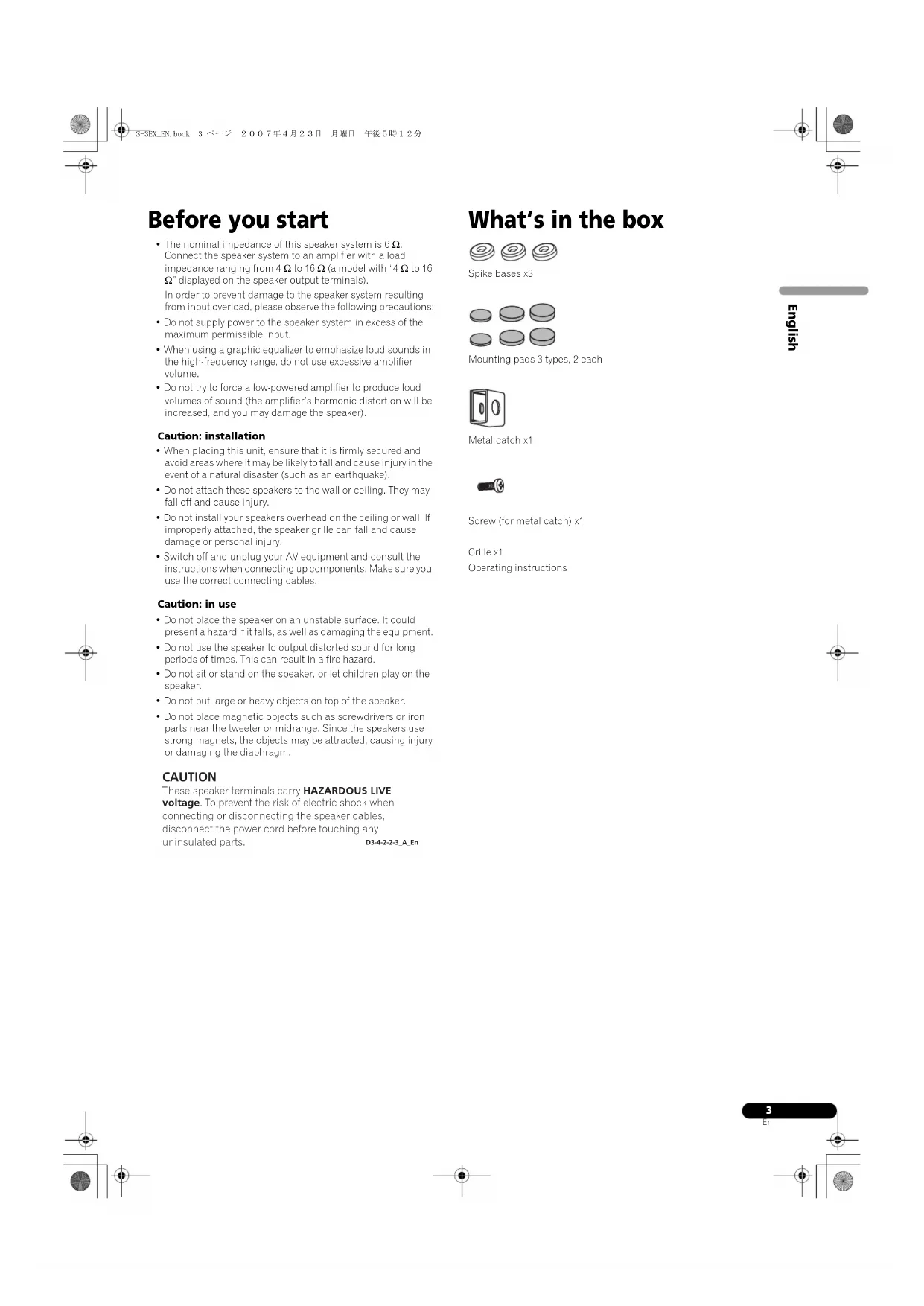
Before you start
The nominal impedance of this speaker system is 6Ω. Connect the speaker system to an amplifier with a load impedance ranging from 4 Ω to 16 Ω (a model with "4 Ω to 16 displayed on the speaker output terminals). In order to prevent damage to the speaker system resulting from input overload, please observe the following precautions:
- Do not supply power to the speaker system in excess of the maximum permissible input.
- When using a graphic equalizer to emphasize loud sounds in the high-frequency range, do not use excessive amplifier volume.
- Do not try to force a low-powered amplifier to produce loud volumes of sound (the amplifier's harmonic distortion will be increased, and you may damage the speaker).
Caution: installation
- When placing this unit, ensure that it is firmly secured and avoid areas where it may be likely to fall and cause injury in the event of a natural disaster (such as an earthquake).
- Do not attach these speakers to the wall or ceiling. They may fall off and cause injury.
- Do not install your speakers overhead on the ceiling or wall. If improperly attached, the speaker grille can fall and cause damage or personal injury.
- Switch off and unplug your AV equipment and consult the instructions when connecting up components. Make sure you use the correct connecting cables.
Caution: in use
- Do not place the speaker on an unstable surface. It could present a hazard if it falls, as well as damaging the equipment.
Do not use the speaker to output distorted sound for long periods of times. This can result in a fire hazard. - Do not sit or stand on the speaker, or let children play on the speaker.
- Do not put large or heavy objects on top of the speaker.
- Do not place magnetic objects such as screwdrivers or iron parts near the tweeter or midrange. Since the speakers use strong magnets, the objects may be attracted, causing injury or damaging the diaphragm.
CAUTION
These speaker terminals carry HAZARDOUS LIVE voltage. To prevent the risk of electric shock when connecting or disconnecting the speaker cables, disconnect the power cord before touching any uninsulated parts. D3-4-2-2-3.A.En
What's in the box

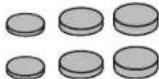
Spike bases x3
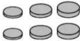
Mounting pads 3 types, 2 each

Metal catch x1

Screw (for metal catch) x1
Grille x1
Operating instructions

About the EX series
The EX series, incorporating the abundant technological know-how behind Pioneer's flagship TAD speaker series, was developed with the goal of creating the ultimate speaker possible in its price range.
The design and production of the EX series result from an international effort that represents the finest in Pioneer's speaker technology.
Technology behind the S-3EX
CST
The core driver of the system is the Coherent Source Transducer (CSI), which draws on the technology used in TAD. The tweeter diaphragm is mounted concentrically within the apex of the midrange cone and provides a point source of sound from 400Hz to 100kHz . The CST ensures a perfect spectral balance between the direct and reflected sounds that arrive at the listener's ears, providing a more consistent sound throughout the listening room and improved imaging capability.
Ceramic Graphite Diaphragm
The CST's tweeter features a ceramic graphite diaphragm that provides top-level strength and dampening characteristics that are practically unrivaled by any other available materials currently used in high-end audio speaker systems. Ceramic graphite's lightness and exceptional strength combine to create speakers whose diaphragm resonance can be pushed far beyond their audible range.
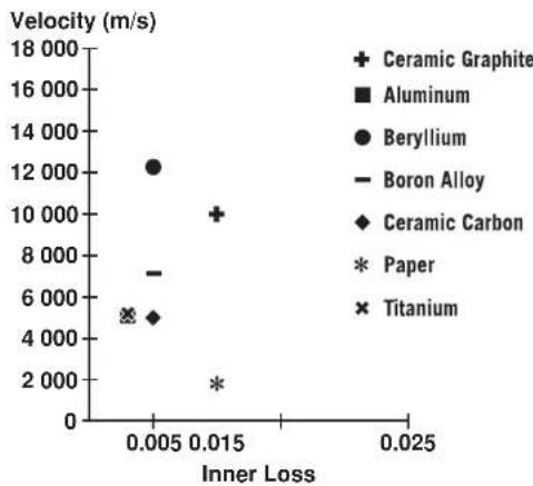
Magnesium Alloy Diaphragm
The CST's midrange features a magnesium alloy diaphragm whose characteristic lightness and high inner loss provide excellent transience and minimal coloration of midrange sounds.
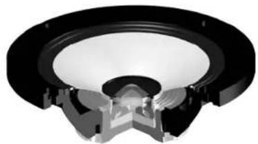
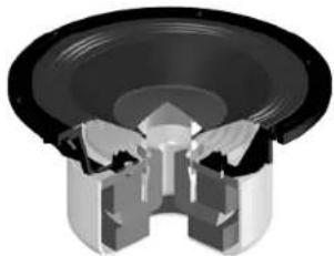
Bass Drivers
The bass driver pictured below serves as the foundation of the S-3EX speaker system. The driver's strength is the result of the Aramid/Carbon composite material, originally created during the development of the S-1EX, that is used in its diaphragm. Pioneer's exclusive LDMC magnetic circuit technology has been incorporated in order to preserve linearity from low to high output levels and minimize distortion.
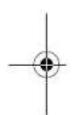
Bass Enclosure Construction
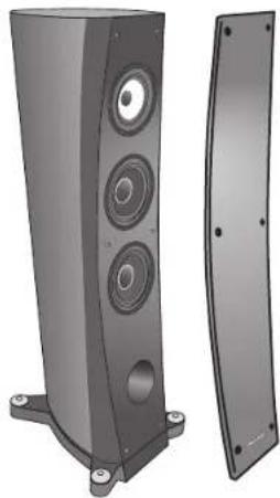
The unique form of the S-3EX is based upon logical necessity. In order to synchronize the arrival time of sound from the CST and the two bass drivers, each driver is mounted upon a baffle that serves to create a highly delicatic curve known as the "precision curve" (see illustration below). Made of up to 100 mm thick MDF (Medium Density Fiberboard), this baffle is, moreover, strong enough to contain the force of the drivers. Additionally, the bass port has been carved out of an extremely thick block of MDF, resulting in the reduction of wind noise for clear, deep bass.
Crossover Networks
The crossover networks use only the finest components. Air cored coils, noninductive resistors, and film capacitors in the signal path are all carefully chosen and optimized for the CST driver to provide the greatest transparency to the signal. The bass drivers use silicon steel plate core inductors that minimize distortion and loss during energy transfer. All components are connected directly to their respective wiring materials, instead of a printed circuit board, allowing for minimal loss and maximum performance.
Collaboration with Air Studios
Since its establishment by George Martin in 1969, London, England's Air Studios has earned uncequivocal respect from scores of artists who recognize it as the world's premier recording studio. The Air Studios seal that was awarded to the S-3EX indicates that these speakers are capable of producing the high-quality sound demanded by the world's top-class sound creators.

AIR STUDIOS
Installation and Placement
How to install
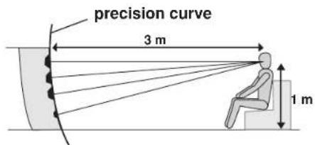
This speaker system is supported by three points (the front two legs, and the back spike located between the back two legs).
1 Choose the location for speaker placement then put the spike bases on the floor.


2 Place the speaker on top of the spike bases.
3 If either the left or right back legs touches the ground before the back spike, resulting in the speaker not resting flat on its placed surface, adjust the back spike so it extends to the ground before either of the back legs.
4 Place the included mounting pads underneath the back legs to keep the speaker stable.
Choose the most appropriate thickness of mounting pad from the several types included.
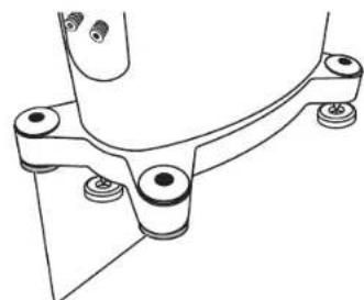
Mounting pad

Important
- Do not place the speaker on an unstable surface. It could present a hazard if it falls, as well as damaging the equipment.
- As a precautionary measure, be sure to not place the unit anywhere where it might fall on a sleeping individual in the event of an earthquake.
- As this unit weighs some 48kg , it is very dangerous to try and set the spike nut while tilting the speaker. Be sure to place the unit on a soft area (such as a blanket) so that it does not damage the floor, and carry out the installation with at least two people.
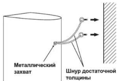
Mounting the Fall-Prevention Fastener
- Using the included screw, tightly secure the metal catch to the backside of the speaker.
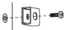
Pass a commercially-available reinforced string through the metal catch to securely support the speaker to the wall. Be sure that the wall to which you fasten the speaker is strong enough to support the weight of the speaker. After fastening the speaker, make sure that it does not fall over.
The speaker can incur damage in the event of a fall.
Do not attach the metal catch directly to the wall. It should only be used in conjunction with reinforced string to prevent the speaker from falling.
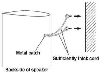
Pass two reinforced strings through the metal catch, and fasten the speaker to the wall as shown above.
Do not place the speaker where it will be in direct sunlight, and avoid positioning it near heaters and air conditioners. Doing so may cause warping and discoloration of the speaker cabinet and damage to the speaker.
Pioneer assumes no liability whatsoever for damages resulting from assembly, improper mounting, insufficient reinforcement, misuse of the product, acts of nature, etc.
Choosing Where To Place The Speaker Systems
Ple t t performance, tonal accuracy, and imaging. All rooms are different and so this section is intended as a guide only. Experimentation in your room will yield optimum results.
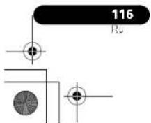
Use the graphic below as a guide to determine optimal speaker placement.
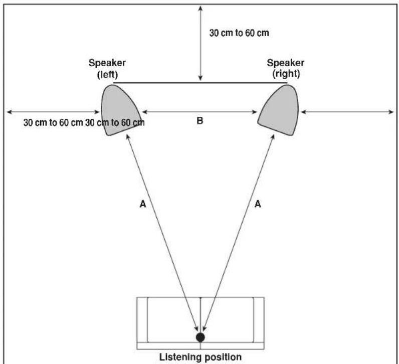
Distance "A" should be equal to or greater than distance "B." Each speaker should face the listening position.

Important
- In areas of high humidity, use a dchumidifier, and in areas of excessive dryness, use a humidifier to adjust the room's humidity level. Avoid exposure to direct sunlight, and do not install in areas near by heating appliances.
Connections
Connecting to an amplifier
This speaker does not include speaker cables used for connecting to an amplifier. Take the following factors into consideration when choosing speaker cables so that you can get the most from your speaker system:
- Use heavy-gauge speaker cable if possible, and keep the cables to the minimum necessary length.
If the length of cable required for left and right speakers differs, use cables of the same length, matched to the longer distance. - Cable have differing characteristics. Keep this in mind when using any cable.
- Select cables with as little resistance as possible, and make sure the cables to the speaker terminals and amp are firm and secure.
Connecting the cables
1 Switch off the power to your amplifier.
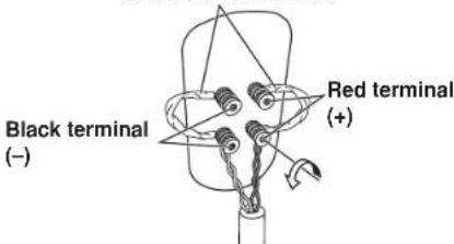
2 Connect the speaker cables to the input terminals (lower) on the back of the speaker. For input terminal polarity, red is positive (+) and black is negative (-) .
3 Connect the other ends of the cables to the amp's speaker output terminals (for more details, refer to your amp owner's manual).
Short bar connectors
- Grasp the cap knobs on the lower input terminals and rotate them to the left (counter-clockwise), insert the speaker cable wires into the holes in the terminal posts, then tighten the knobs to secure the short bar as well as the wires.
- You can also connect the speaker's terminals with a banana plug. When using a banana plug, be sure to remove the cap at the tip of the input terminal.
After connecting the plugs, pull lightly on the cables to make sure that the ends of the cables are securely connected to the terminals. Poor connections can create noise and interruptions in the sound. - If the cables' wires happen to be pushed out of the terminals, allowing the wires to come into contact with each other, it places an excessive additional load on the amp. This may cause the amp to stop functioning, and may even damage the amp.
- When using a set of speakers connected to an amplifier, you won't be able to obtain the normal stereo effect if the polarity of one of the speakers (left or right) is reversed.


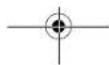

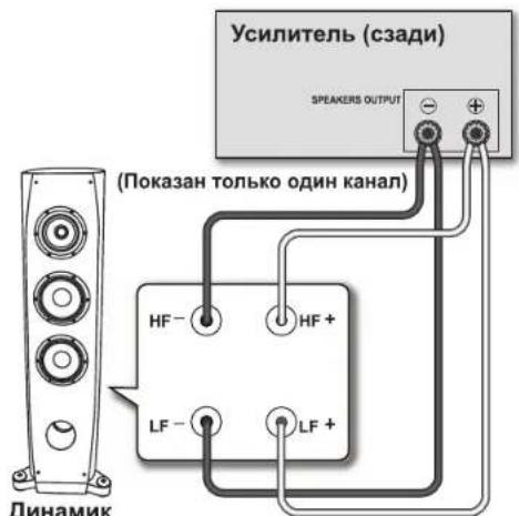
Single-Wire Connections
For single-wire connections, connect the mid-to-high- and low-frequency sections of the crossover network with the shorting link that was included with this unit, then connect the (+) wire from your amplifier to either red binding post and the (-) wire from your amplifier to either black binding post, as shown in below.
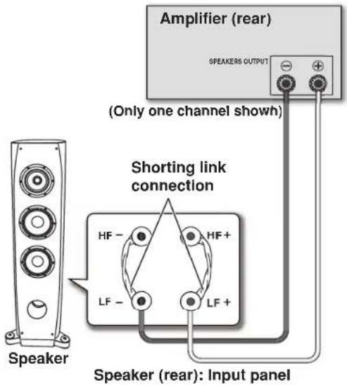
Bi-Wire Connections
In a bi-wiring connection, you independently plug in the speaker systems running from the amp to their respective high- and low-frequency plugs. This results in the CST driver and bass drivers being independently connected directly to the amplifier, offering you the freedom to optimize the cable type for each of the drivers. Connect one set of wires to the bottom set of binding posts (bass driver-specific network). Then connect a second set of wires to the top binding posts (CST-specific network). Next, connect both sets of wires to the appropriate terminals on your amplifier. Take care to connect both (+) wires to the (+) amplifier terminals and both (-) wires to the (-) amplifier terminals, as shown below.

Bi-Amplification Connections
Bi-Amplification allows the best performance when using dedicated amplifiers for low- and mid-to high-frequency sections. There are two possible configurations, commonly referred to as horizontal and vertical bi-amping.
Caution
Remove the shorting links before connecting speaker cables in bi-amplifications connections. Failure to do so may result in damage to your amplifiers.
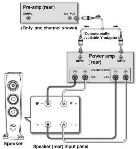
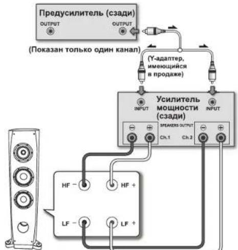
Vertical Bi-Amping
With this configuration, identical stereo amplifiers are used for each speaker system. One channel of each amplifier drives the low frequency section and the other channel drives the high frequency section, as shown below.
Connect one set of wires and amplifier channel to the bottom set of binding posts (bass driver-specific network).
Then connect a second set of wires and the other amplifier channel to the top binding posts (CST-specific network).
Take care to connect both (+) wires to the (+) amplifier terminals and both (-) wires to the (-) amplifier terminals.
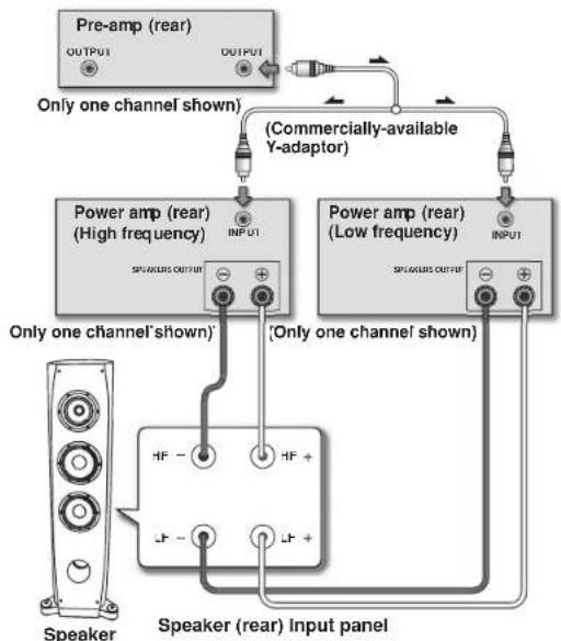
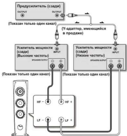
Horizontal Bi-Amping
With this configuration, you may use different stereo amplifiers for the low- and mid-to-high-frequency sections of the speaker system (e.g., tube amplifiers for high frequency and solid state for low frequency). Each channel of one amplifier drives the low-frequency section of each speaker system and each channel of the other amplifier drives the mid-to-high-frequency section, as shown below.
This method requires that both amplifiers have the same gain: otherwise an imbalance will be heard between the low- and mid-to-high-frequency reproduction from the speaker system. If in doubt, please consult your local dealer.


Other Information
Attaching/Removing the Grille Cover
This speaker system comes with grille covers which may be attached and removed by:
1 To attach the grille cover, line up the holes on the speaker with the inserts on the grill, and press firmly.
2 To remove the grille cover, grab it by its bottom with both hands and gently pull toward you to separate the bottom part of the grille from the speaker.
3 Slide your hands up to the middle section of the grille, and once again pull gently toward you. This will remove the middle section of the grille from the speaker.
4 Finally, repeat this same motion for the top part of the grille, removing the grille entirely from the speaker.

Cleaning the speaker cabinet
With normal use, wiping with a dry cloth should be sufficient to keep the casset clean. If necessary, clean with a cloth dipped in a neutral cleanser diluted five or six times with water, and wrung out well. Do not use furniture wax or cleansers.
Never use thinner, benzine, insecticide sprays or other chemicals on or near this unit since these will corrode the surfaces.
Specifications
Enclosure. Bass-reflex floorstanding type (magnetically shielded)
Configuration 3-way
Woofer 16 cm core x
Mid tweeteter 14 cm cone/3 cm dome
Nominal impedance 6 Ω Frequency response 30 Hz to 100 x1
Sensitivity. 88.5 dB (2.63 V)
Maximum in put power 160 W Exterior dimensions. 350 (W) mm x 1224 (H) mm x 541 (D) mm
Weight 48 kg
Supplied accessories
Spke bases 3
Mounting pads 3 typs,2 cach
Metal catch 1
Screw (for metal catch) 1
Grille 1
Operating instructions

Note
Specifications and design subject to possible modification without notice, due to improvements.
Magnetic shielding
This speaker system is magnetically shielded. However, depending on the installation location, color distortion may occur if the speaker system is installed extremely close to the screen of a television set.
If this happens, turn off the television, then turn it on again after 15 min to 30 min. If the problem persists, place the speaker system away from the television set.

is a trademark placed on a product with Pioneer's Phase
Control technology. This technology enables high-grade sound reproduction through each component by improving overall phase matching.
Published by Pioneer Corporation.
Copyright © 2007 Pioneer Corporation.
All rights reserved.
Bi-amplification vertical
Publication de Pioneer Corporation.
© 2007 Pioneer Corporation.
Copyright © 2007 Pioneer Corporation.
Tuttiririservati.
Montagcschijes 3 typen. elk 2 stubs

Metalen beugel x1
spuepepepepepepepepepepepepepepepepepepepepepepepepepepepepepepepepepepepepepepepepepepepepepepepepepepepepepepepepepepepepepepepepepepepepepepepepepepepepepepepepepepepepepepepepepepepepepepepepepepepepe

Belangrijk
Copyright © 2007 Pioneer Corporation.
Copyright © 2007 Pioneer Corporation.
"Copyright" © 2007 Pioneer Corporation.
Skruv (for metallake) x 1
GrII x 1
Bruksanvising
Om EX-serien
Copyright © 2007 Pioneer Corporation.
Med ensamrtt.
Published by Pioneer Corporation.
Copyright © 2007 Pioneer Corporation.
All rights reserved.

Copyright © 2007 Pioneer Corporation.
Copyright-oikeudet © 2007 : Pioneer Corporation.
MembpHa H3 cIIaBa MarHn 114
HH3KoactOTHbc paiibcpbl 115
BcpoeHbIe H3KoyacToTHIe rpomKorOBopTeJI 115
Pa3nnte.115
Pa3pa601K B c0pTyHmHeC b C Air Studios 115
YcTaHOBKa n pa3MeUeHHe
PpABnIyCraHOBKn 116
YcTaHOBka KpncKa 3aunHtIOTnAChn. 116
Bb6op mccta 118 pa3McHnH akycTHCCKHX cHcTcM 117
CoeHHHeHn
PiueeHHHeH K ychHreHIO 118
1 BbIepeTe MeCTo Iy TaTHOBKn DnHaMnKa npacnooxKeTcOHOBaHN KOHycOB Ha nOy.


2IOCTABTe DnHAMK Ha OCHOBAHNA KOHYCOB.
3 B cnyae ecnn nebaa nn npabaa 3adnna HoKka kacaotc nana npexde, yem do nona Doctae T3adn Hnn, Bpe3yIbTate Yero DNHAMNK CTOTN HA NOBepxHOCNT yctahOBKn HEOBHO, OTperynpyte 3adn Hnn TaKIM o6p3om, YoTo bO IH OoCTaBn NOBepxHocTN npExde Kaokn Nnbo n3 3adHnx HOKe.
4 Pacnooxte yctahOBouHbIe noDKJaKn no3aDnHe HOKK, YTO6bl oBcneuHTb CTaBbHOCTb DnHaMnKa.
Bb6epHrte yehHOBOHIOHOJIOJIaIcKy HANBOJOce HOxOJIHcH ToHHHnH3 HeckoIbIKHnPnHaRaCmBHX THIOB.

UcTaHOBouHnA NOklaIaKa
YcTaHOBka Kpenexa 3aunTbI OT NaDeHnA
C HOMOJIbU npIaIeAMoI 60IIaIpuOIOA KHeJIpeI MEaL.IBUPCKN 3AXBHT aHdJIaIbHEJIeIN DHHAMHK.

IipohyctHHe HmEOHHnB C HpOaJke HpOHy hHyp Hepe3 META.IIIEeckn 3axBHT,106bHaJeKHO IIHKpeHb IHHAMNK K CTHE. Y6eHITcB B TOM, TIO CTHE, K KOtOpOH fIKCUPyETC IHHAMNK, HMeT IOCTAOHYIOPOHOCb,106bMyEepKaB Bec DIIHHAMNK. IocTe 3akpeHHeHH IHHAMNK, y6eHITcB B TOM, TIO OH He ynaet.
IIaHeHH HeHHAMHKa MoKET IIpHHTHHITb yIep6.
He npHKepeHHJIte MeTaIINHueCkH 3axBAt HHeOepeCTBeHHIO K
TcIEc. Ero cJeYer HcHOBJbONaBt TohIKo II cOeHTAHNN CO HHPOM
HOBBHHeHH JOEeKoeh TJIb HpeOTbPAuHH HAeHH
HIMAMKA.
3aHnA CTOPOHa DnHaMnKa
IPOHYCTTIEHJINHYPNAHONHIIHINIOIPOHIOCTHEPE3Meta.TIHUCCKHI 3AXBHTI INHPKPEITTEJHHAMHK CETHC,KAK 3TO HOKASIIIO BEPXY.
He pa3MeaIte DnHAMK B MecTax NOI pRmblIM NuyAMn CoJIneHOrO CbTa, a TAKKe I36eAaTe MeC T B6IINOT HArpeBaTeNe I KOHNIOHepOB. HecoBIOJeHMe 3TOrnpabNl MoKet npNBecTH K DeOpMaunu OBeOCUeHbAHIO KOpNyCa DnHAMKAn Nnn NobPeDITb DnHAMK.
KOMnHaPioneer He Hecet OTBETCTBEHHOCTb NO B03MeUeHHNO KAKIN-NI6O y6bIKOB, NOHECEHHbIX B pe3yIbTate c6OpKn, HENpaBUNbHOro MOHTaKa, HEDocTatoUHOro KppeNHe, HENpaBUNbHOr 3KcNpyatauH n3dJIeN, RaBHeN npipOdbI T. d.

Baxkho
He p3meiHHe DnHAMHK Hn HeYcTOHBO HOBepXIOCTn. HaeHHe DnHAMKMOKeT CO3dABt BHOACIOCTn DnHOe, a TaKKe CTATb npHHIOH OOBpeKHeHH O6OpyIOBAHH.
B KaucctBe MepeIpeIOCTOpOKHocTH, HNKoHa He pa3MeaHe yCtPOcTBo B Mecie, OTkyda OHO MOKeT yHactb Ha CnHmero HeIOBeka B clyae 3eMIEpaceHH.
IOKcKbkyBecnnnoyOCTPOCTBAcoTBBETOKO48K,ue3buaHIOHACHO HATBcpeYIHPoBHbIaIKHINHA,HAKIOHnIbHtOM 1HAMHK.Ob63aIIbHIOJIaHcyTOyMIKyoIOHEpXIOCTb(HAHPmep,IIaOEIO).UTo6bHe HOBpeHTb HOKpblteHOJIA.H BbHIIEeOyctAHOBKy KAKMHHMYMBAEOm
Bb6op MeTa dIpa3MeueHnAkyctuYeCKnx CNTeM
Bb6op Mccta p3mncnHn HOMCnHn npocnynnHn HkOaHbact orp0mHc HnHnHe h KaCCTNO 3yauHHn H pa6oHc XapakTePCHTHK
acytHnckcoi cTcMnS-3FX, taekn kac: 3yuaHnce bacoN ToHoCTe NpCDAu TOnHIOCTei n 3ykoBOrOcbpa. ItockOJIky BCC NOMCnHn
HMOT CBOH HINHNHyaNNbc OOC6CNHO, DAAHn PAJcN PpcN HENCOHIOAHI TOKBO H KAcCTc NOIero cnpabOHIO
pyKOIOCTBa. Bb EMOXCTe Do6hTbe OHNTNHOI rpoCByIbTa, EKcnPmEHTHPy e cytantooKoi B aHcII KomHc.
IIOJIb3yIreIeI npHReIeHHBM IHHKe IpaHkOM 1Jr cHpaBKN HpH OIIpeIeIeHHN OHTHMaJIbIHO MecTa paHIOJOKeHHN JHIMAMKa.
PacctoHnE“A”doJxHO paBHTbcnnIpeBOcXOHTb pacctoHnE“B”. KaxdbI dINHAMNK doJxKen pacnonarTaBCFPOHTaBHOaCTbKO MeCTy CnyataTEn.

BaxHo
B MECTAC B HIOKOH HIXKHOHJOHOJYTECB HIOHOJOHOJTEM, A B CYHXM MCTAC C ppeMePHO IH3KOI B HIXKOHO YHAXINTHEIEM BO3yxa, YTO6b HOIEpHKBaTH B HIXKOHTB HOHEMOH IOHOJIOHM yPOBJE. H36eJIte HOIAADHHN HAHNAMKH IHPMAx COIIeHbX JHyeh H ne cTtHBAHBAHHe DnHAMNK B MECTAC 6013HOTI HPePAETBeBHx UPbOpB.
CoeHHnHeHn
DByXnpoBODhbIe COeHNHeHn
Bdyxnpoohn KOHpyaHH Akycttccckc Hcetcmbl NOHIOHOAOTNCI3ABCHMMN COOHNCHNM OT yCHHTTcK COOTbCTryOHm BILCOKAoCTOHBM N IHHKOaactOTBHIM KOHAKTHM PAHcEMAM. AKHMOBAPAM, JpAHBcPST H IN3KAcHCTOTBHIM APAHBepbI HOJIOHOaTOER NCABHEMO HHOepeCfTHCHIO K CYHIHTTEHO, WTO IpcOCTABHCT HO3MOXHOCTb BIBOpa OITHMALIO TINHA KaeBNIJA KAKHOIpaHepa B OTENHOCTNIOCoEHNIIEO OyHApIPOBOID K HIXHHeHAp COKTAHIX KIEMM (IeB IIIN3KoACTOTHO DUNHAMiKA). 3ATcM HOACOEHHITE BTOPYHApH npHOIOBIK BepxHHeHape KOTAKTHHX KIEMM (IIIN, CST). 3ATcM IOcEOHHITE Obe HApIPOBOID K COOTBCTYBOHHOM KONKTAAHUM PA3BeEMAM HA YCHHTTEJE. CO6HOJIaTe HOHHPoCTb: HOOCoeHHITNE oBa IPOBOJa (+) K KOHAKTHM PA3bEMAM (+) HA yCHHTTEJE, a Oba IPOBOIA (-) K KOHAKTHM PA3bEMAM (-) HA yCHHTTEJE, KAK 3TO IOKASIIHO HIN3Y.
Диhamнк(с3адn):пань BXoDHbIX KOHTaKTOB
CoeHHeHH B CxMe C DByXKaHaJIbHbIM yCUNHeHEm
[ByxKahaihnooc yenHnnc (Bi-Amplification) no3Bolctn polyuHb cAmoc bkoKoKc Kacctro 3yuaHn pH nO103OBaHn orJcIbHX yehntncn Jccknn HkHHX aotcr H ccknn cpeHn Hbcoknx aactcr. Cynctctyr BcBO3MOKHeK konphpyauH, kOTpEe o6bHn haabaHOTRHOHTAIIHAA cxema] H REPHKAJIINH CXMA] ByxKaiHaHoro ycHcnH
BHHMaHne
IpeHIOOCHEHHeHEMKaeH HAMHKOB KIOHIFHYaHHYbXKAaHaIBHOYcHIEHN YaHHTe 3AmbKaOHNE HepMbHKn. HecobHyCHNC ETO ykaaHMOKeT HpBecTH KOBPeKaeHNOyHHTeN.
BepTikKaIbHaNcXeMa dByxKaHaNbHoro yCnHeHHa
B301 KOUHUYPAUHH DIAKJIOAkyCTYNECKOCHCTREMHIOHBYIOI C HENTHINHEyC HHTIEH. OHNKHANKAHKOAKOTO yCHHTIEHOHOEOAHHETcK cekuHHN BHKX hCTOT, apyTOI KAHAI-K cKcHHBBOCKHX AOT, KAK 9IO IOKA3AO BH3Y
IIOcoeHHHTe OHy npy IpOBOOB KaHJIa YcHINrEIM K HIXKHe Iape KOHTAKTHbIX KJEMM (ueBb H3KOYACTOTHOI INHAMKa).
3aTcMIOeocHHHTRETOPOHPOHOJpyrTOKANAA yHHTENK BepxHnape KOHTAeKMM (CST).
HnHAMNK HnHAMNK (c3a)PiHaHeB BXoDHbIX KOHTAKTOB
Topn0HTaIbHaC xEma DByXKaHaIbHorO yCunHeHH
BTOI KOHHPHpyaHH BIMoKRe HCHOB3OBaBHpaHHHbtepeoOHnueckHe yCHHIEHn PAeBIOHO BIN CEuHHN HCKHX qACTOIN CekHHB BEXCOHKY ACTOT AkyCTHECKO CHCTEMH (HAHIHMep,AMIOHbY CYHIIIE. IIB DABBCOKH YACTOT HIOUYPOBOHNKOBy cHHTIE.BI IN HN3KHX YACTOT).KAkDa KAHAI OAnHO YcHHITENHIOHQUHTEC KHN3KQHACTOTHO NcKHHN AkyCTHECKO CHCTEMH,AKKaD KaHAI APyTOO YCHTHEID -K cKTHIN CpeHHX H BcOKHX HACTOT, KAK 3IO IOKA3HO BHNY.
1HnHCIOB0AHIN HNHOI METoJA COEHHHEH Heo6xOJIHMO,
TObMo 06a YCHHTENHe HMEHN OOHAKOBK BOOΦHUNHEY CHJNEHBA B IPOTHBHOM CNYAe MEKUY HNKOJACOTOTHMH N cpeJeH BBCOKOIACTOTHMH 38yKaMHNBOCPNOH3BOHMMH AKCYTHeckOCHCTeMOH.6yET HAOITDAECB HcBnYBaC NOBHTCR KAKHe-TH6O comHeHH HIN BonPcBo, opaTHTec 3a KOHCytTaunHe K MeCTHOHNepy.
HnHaMnK (c3aHn): NaHEnb BXoHbIX KOHTaKToB
Другая Информация
YcTaHOBka/CHrTne peWetKn dHAmnKa
JaHnAkyetuuecka ChcTeMa NoctanRrctc Pc nntkAMHa HncpeHn mncnHn HnAMHKa, KOTOpb MoKHO CHRTb, BnIOJIHHB cIyOJIOU OoPAnHIO
1 7ro6bI yctahOBHTpeWETky, BbyIOBHNTe Na3bHa KaONOHKe CBTyINKaMn Ha peWETke N C cNIOH HAKMNTe doynopa.
2 Tc0bI CHRTb peWETKy, BO3bMMTE ee 66eHNM pyKAMn 3a HNKHIOO qACTb N octOPKOHOT NaCeB, Tc0bI OTDeNtBu HNKHIOO qACTpeWETKn OT KOHNK.
3 NpeBnBte pykB CpeHIOO qactb peWetkn n eue pa3 octopkoNOIHTNEe Ha ce6a.3HM Bbl OTdennite cpeHIOO qactb pweTkn OT KOONKn
4 Hakoehu, NOBTopb TO xe camoe DeCTBne DnB BepxHeuactn peWetKn, NIOHocTbHO CHMNTpe WwETky C KOLOHN.
Kopnya DnHaMka
B 06bHbX ycIOAHx 0KcIpyaTHiN IOCTaTOHO npHOuCckn pOHTpAHT KOpNc cyXoi TKAHIO, YTO6bI NOIcPKNBAt B KOpNc B HcHOTc. Pn Hco6OdHMocTH, pOHTpAITc TKAHIO, cMOUChHON HcHPTaJIbHM MoIHUM cpcETROM, pa36BaTCHHM I:5 HIN I:6 BOIOH, II XoPOHIO BHKATOH. He NIOb3yHITcB BOCOM HIN MOIOHHM cpcETBAMH IN Mc6CmH.
HKnKo7aIcNoIb3yIteBpactnOpHTeHH6ChHOM, HNCKTHINHHNPAckHJITCHNHNJpyTHMN XMHNECKHM HNCCTBHMAH aHINPBOM cJIHHM yctpoHbTBO, NOKOJIbky 3TO B3OBCT Koppo3HOHbCPXHO.
TexHnueckne xapaKTepeNCTNK
Kopiny HanoIHLoro THa c oTpKaTeJcM cAcB (MARTHIOKOJIAPHPOAHHI)
KoHpypann 3nOtoe HN3KoHaCTOnTHBdHHAMHK 16-cm KOHycX2 CpeHBeBCOaHCTOnTHBdHHAMHK 14-cm KOHyc/3-cm KYIOI.
HOMHHJHIOHOJOHOCHOPOTMHJEH HAZTOHTHA XAPAKCTPCHSA 301u do 100kl u
UyBCTBHtCtBHOCTb 88.5 AB (2,83 B)
Makchinen Bxion MOnIOIOCT 160BTr IabapHTIIPOPMPE 350 (III) x 1224 (B) x 541 (I) MM
Bec. 48 kr
NoctabJrEmbIe B KOMnKeTe npHaJnxHocTH
OCHOBHNN KOHYCOB 3
YCTAHOBOHMBIe NOKIAJIKN . 3THIIaNO2R KAKIQOM
MeTALHECKHI 3XXBAT 1
BOIT (DJIH MEHALHECKKO 3XBAIa) 1
PeWETKA 1
HnctpyKHH no 3kntyataaHH

3aMeHaHHe
TexHHueckHe XHPKTEPCHTHKN KOHCTpyKTHM OMTY MEHTbCh 63 HpeBaprrbHO ryeBOMdHEH, B CBAH C BHOCHMMH yCOBepHECTBOBAHHN.
MarHHTHOe 3KpaHnPOBaHne
AaHaa AkyTHeCKA CHCTeMa3iHHeMAHTHTbHM 0KpaHHoBAHm. OJHaKo, BABCHMOCTH OT MeCAyTcHOBKH, MOTy BOHHaht bIETOBc HcKaKeHH, cCtH AkyTHeCKA CHCTeMa yTaHOBcHc CnHkOM 6hN3KO K OkaHy TeneBHOpa.
EETIOIPOHOHOT,BAKIOHTTCETCBTHIOH IN BAKIOHTCRO CHORA Hepe315do30MHHT.EcIHIOPOBEMAcoPAHaeCTIEPENEMeHTHE AkyCTHECKYIO CTICREMY NOAIBBUEO TOTEBHBIO

TTOBAPHM 3HAKOM, HAOCHIMM HA PNOyKTH, B XPHMCCTCRXHOHOR pCyrHPOBKn pa3n Pioneer Phase TaHHA TXXHOHNOHOHOT NOYATy.
BICOKOKAHCTCHHOC 3YUAAHNC HOCPONH3ROHMHX KAKTHM KOMIOHCHTOM 3YKOB HOPECDTBOM HOBHHCHHH TOHOCTH HaCTPOHN yponoI pahsnoHN.
Hsiao Pioneer Corporation.
3aHmHHeIO ABTOPcKHM UPaBOM © 2007 Pionccr Corporation.
Bce npaba coxpaHcHb.


Примочинe:
B cootbetctbnn co ctaTbe 5 3aKoHa Pocncko Fepaun "O 3aunTe npab nptpehtna Yka3aanem PpaNTeNbCTBa Pocncko Fepaun N720 ot 16 noHra 1997 rda kopnpaun Pioneer Europe NV yctanabnaet ycnobne ha cnedyuoy npdoJnKeTbnbHoctb cpoKa cnYkbI oPhiuaNbHO nocTabnembx Ha Pocnckn pbHOK TObapOB.
Aynio n BndeooobopyoBaHne: 7 net
Ipehenochoe aydnoo6opydoBaHne:6 net
Dpyroe obopydOBaHne (hayuHNK, MKNpOoH nT.D.): 5 net
ABTOMO6nIbHaJ 3NeKtPoHnka:6JeT
D3-7-10-6_A_Ru
http://www.pioneer.co.uk
http://www.pioneer.fr
http://www.pioneer.de
http://www.pioneer.it
http://www.pioneer.nl - http://www.pioneer.be
http://www.pioneer.es
http://www.pioneer.pt
http://www.pioneer.se
http://www.pioneer.dk
http://www.pioneer.no
http://www.pioneer.fi
http://www.pioneer-rus.ru
http://www.pioneer.eu
Published by Pioneer Corporation.
Copyright © 2007 Pioneer Corporation.
All rights reserved.
Publication de Pioneer Corporation.
© 2007 Pioneer Corporation.
PIONEER ELECTRONICS (USA) INC.
P.O. BOX 1540, Long Beach, California 90810-1540, U.S.A. TEL: (800) 421-1404
PIONEER ELECTRONICS OF CANADA, INC.
300 Allstate Parkway, Markham, Ontario L3R 0P2, Canada TEL: 1-877-283-5901, 905-479-4411
PIONEER EUROPE NV
Haven 1087, Keetberlaan 1, B-9120 Melsele, Belgium TEL: 03/570.05.11
PIONEER ELECTRONICS ASIACENTRE PTE. LTD.
253 Alexandra Road, #04-01, Singapore 159936 TEL: 65-6472-7555
PIONEER ELECTRONICS AUSTRALIA PTY. LTD.
178-184 Boundary Road, Braeside, Victoria 3195, Australia, TEL: (03) 9586-6300
PIONEER ELECTRONICS DE MEXICO S.A. DE C.V.
Blvd. Manuel Avila Camacho 138 10 piso Col.Molas de Chapultepec, Mexico,D.F. 11000 TEL: 55-9178-4270
K002_B_En
CdeNaHO B Kntae
Printed in China / Imprimé en Chine

- Pioneer sound.vision.soul
- S-3EX
- Contents
- Before you start
- What's in the box
- About the EX series
- Installation and Placement
- Connections
- Other Information
- Caution: installation
- Caution: in use
- CAUTION
- Technology behind the S-3EX
- CST
- Ceramic Graphite Diaphragm
- Magnesium Alloy Diaphragm
- Bass Drivers
- Bass Enclosure Construction
- Crossover Networks
- Collaboration with Air Studios
- How to install
- Important
- Mounting the Fall-Prevention Fastener
- Choosing Where To Place The Speaker Systems
- Connecting to an amplifier
- Connecting the cables
- Single-Wire Connections
- Bi-Wire Connections
- Bi-Amplification Connections
- Vertical Bi-Amping
- Horizontal Bi-Amping
- Attaching/Removing the Grille Cover
- Cleaning the speaker cabinet
- Specifications
- Supplied accessories
- Note
- Magnetic shielding
- Bi-amplification vertical
- Belangrijk
- Om EX-serien
- YcTaHOBKa n pa3MeUeHHe
- CoeHHHeHn
- Baxkho
- Bb6op MeTa dIpa3MeueHnAkyctuYeCKnx CNTeM
- BaxHo
- CoeHHnHeHn
- DByXnpoBODhbIe COeHNHeHn
- CoeHHeHH B CxMe C DByXKaHaJIbHbIM yCUNHeHEm
- BHHMaHne
- BepTikKaIbHaNcXeMa dByxKaHaNbHoro yCnHeHHa
- Topn0HTaIbHaC xEma DByXKaHaIbHorO yCunHeHH
- Другая Информация
- YcTaHOBka/CHrTne peWetKn dHAmnKa
- Kopnya DnHaMka
- TexHnueckne xapaKTepeNCTNK
- NoctabJrEmbIe B KOMnKeTe npHaJnxHocTH
- 3aMeHaHHe
- MarHHTHOe 3KpaHnPOBaHne
- Примочинe:
Brand : PIONEER
Model : S3EXQL
Category : Pregnant