
CM-S54T - Loudspeaker PIONEER - Free user manual and instructions
Find the device manual for free CM-S54T PIONEER in PDF.


| Product Type | Surface Mount Speaker |
| Series | CM Series |
| Model | CM-S54T |
| Loudspeaker Type | Two-way passive, reflex-loaded |
| Frequency Response (-10 dB) | 95 Hz – 20 kHz |
| Sensitivity (1 W / 1 m) | 87 dB |
| Nominal Impedance | 8 Ω |
| Power Handling (RMS) | 40 W |
| Power Handling (Program) | 80 W |
| Transformer Taps (70 V) | 30 W, 15 W, 7.5 W, 3.75 W |
| Transformer Taps (100 V) | 30 W, 15 W, 7.5 W |
| Maximum SPL (peak) | 109 dB |
| Dispersion | 120°H × 120°V |
| LF Driver | 4.5" (114 mm) cone |
| HF Driver | 1" (25 mm) silk dome tweeter |
| Connector | Euroblock (4-pin) with loop-through |
| Enclosure Material | PP (Polypropylene) |
| Grill Material | Punched Aluminum |
| Environmental Rating | IP54 |
| Dimensions (W x H x D) | 154.9 × 250.6 × 144.5 mm (6.10" × 9.87" × 5.69") |
| Weight (including U-bracket) | 3.4 kg (7.5 lbs) |
| Rigging | Supplied U-bracket; 2 × M6 threaded mounting points on rear |
| Color Options | White (CM-S54T-W) or Black (CM-S54T-K) |
| Protective Circuit | Built-in tweeter protection (reduces output on overload) |
| Accessories Included | U-bracket, knob screws, Euroblock connector, connector cover, fall prevention wire with hardware, bracket caps, screws |
Frequently Asked Questions - CM-S54T PIONEER
User questions about CM-S54T PIONEER
0 question about this device. Answer the ones you know or ask your own.
Ask a new question about this device
Download the instructions for your Loudspeaker in PDF format for free! Find your manual CM-S54T - PIONEER and take your electronic device back in hand. On this page are published all the documents necessary for the use of your device. CM-S54T by PIONEER.
USER MANUAL CM-S54T PIONEER
Installation and Instruction Manual

CM Series
Surface mount speaker
CM-S54T / CM-S56T/ CM-S58T
http://pioneerproaudio.com
For installation and other support information, visit the above site.
Introduction
Thank you for purchasing this product. Be sure to read the "Read Before Use" before using this product. Also, read the installation and user's manual from the support site that can be viewed from the URL or QR code given here. You may require the installation and user's manual in future, so keep them carefully at a safe location.
http://www.pioneerproaudio.com/en/sound/ceiling/surfacemountspeaker.html

Read Before Use (Important)
RECORD THESE NUMBERS ON YOUR ENCLOSED WARRANTY CARD AND KEEP IN A SAFE PLACE FOR FUTURE REFERENCE.
D36-AP9-1_A1_En
[For American Users and Canadian Users]
The Safety of Your Ears is in Your Hands
Get the most out of your equipment by playing it at a safe level – a level that lets the sound come through clearly without annoying blaring or distortion and, most importantly, without affecting your sensitive hearing. Sound can be deceiving. Over time, your hearing “comfort level” adapts to higher volumes of sound, so what sounds “normal” can actually be loud and harmful to your hearing. Guard against this by setting your equipment at a safe level BEFORE your hearing adapts.
ESTABLISH A SAFE LEVEL:
- Set your volume control at a low setting.
- Slowly increase the sound until you can hear it comfortably and clearly, without distortion.
• Once you have established a comfortable sound level, set the dial and leave it there.
BE SURE TO OBSERVE THE FOLLOWING GUIDELINES:
- Do not turn up the volume so high that you can't hear what's around you.
• Use caution or temporarily discontinue use in potentially hazardous situations. - Do not use headphones while operating a motorized vehicle; the use of headphones may create a traffic hazard and is illegal in many areas.
S001a_A1_En
[For European Users]
![PIONEER CM-S54T - [For European Users] - 1](/content/2026/05/1128157/images/da73614d2df80eee1ab9380c4bec6d28e3e32dff506fb10f3f70799c3483a8e3.jpg)
If you want to dispose of this product, do not mix it with general household waste. There is a separate collection system for used electronic products in accordance with legislation that requires proper treatment, recovery and recycling.
Private households in the member states of the EU, in Switzerland and Norway may return their used electronic products free of charge to designated collection facilities or to a retailer (if you purchase a similar new one).
For countries not mentioned above, please contact your local authorities for the correct method of disposal.
By doing so you will ensure that your disposed product undergoes the necessary treatment, recovery and recycling and thus prevent potential negative effects on the environment and human health. K058b_B_En
![PIONEER CM-S54T - [For European Users] - 2](/content/2026/05/1128157/images/5b41e33da867cda38e6c7204ad81a1b79f95e3db6367b1c79ff4122649ca191d.jpg)
WARNING
Installation
This loudspeaker should be installed by a professional installer. There is a risk the loudspeaker may fall. Ask a professional installer that possesses sufficient skills and experience to install the loudspeaker. Two or more workers are also recommended for installation.
AlphaTheta Corporation bears no responsibility for accidents and damage resulting from deficient installation or mounting, misuse, modifications, and/or natural disasters.
Only the workers installing the loudspeaker should be near it during installation.
There is a risk of injury if parts fall.
Tighten the screws and bolts to the indicated torque.
• Falling of screws and bolts may result in injury or accident.
- The knob of the knob screw for the U-bracket is for temporary fixing. For permanent fixing, use a torque wrench to adjust the torque and then fix it in place.
When installing the loudspeaker on the ceiling or a wall, ensure safe installation by confirming the strength of the installation location and checking the installation method.
If the installation location or installation means such as installation fixtures, etc. do not have enough strength to withstand the mass of the loudspeaker system, it could result in falling of the loudspeaker. Also, be sure to implement redundant safety measures such as by using the supplied wires, etc. If the length of the supplied fall prevention wire is not sufficient, arrange for a wire with appropriate length and strength in consideration of the speaker weight and installation condition. Secure the fall prevention wire on the building at a location different from where the loudspeaker mounting fixture is secured on the building.
Do not install the loudspeaker in the following environments.
- Locations with a large amount of oily smoke and smoke for theatrical or stage performances.
- Locations that are constantly exposed to water.
- Locations with a large amount of oily smoke, such as inside kitchens or factories.
• Unstable locations, such as those exposed to vibrations. - Locations where flammable materials are used, such as alcohols and aerosol insecticides.
- Locations affected by heat generation, such as near light fixtures or heaters.
-
Locations exposed to direct sunlight.
-
Locations where salt damage or corrosive gases may occur.
- Locations where clumps of accumulated snow may fall.
There is a risk of deformation or discoloration of the enclosure and failure of the loudspeaker, which may result in fire or the loudspeaker falling in a worst case scenario.
When installing the loudspeaker outdoors, make sure to install it at a location away from direct contact with rain or sunlight, such as under the eaves.
Large amounts of rainwater and ultraviolet rays can cause deformation or discoloration of the enclosure and failure of the speaker, which may result in fire or the loudspeaker falling in a worst case scenario.
Take snow protection measures.
Piling of snow may cause falling of the loudspeaker, thus resulting in injury or accident. Take measures against accumulation of snow on the loudspeaker.
Usage Methods
Be sure to inspect the loudspeaker after an earthquake.
A problem with the mounting part may occur, which could cause the loudspeaker to fall.
Do not open or modify the interior of the loudspeaker.
The interior has high voltage components, and there is a risk of fire and electric shock. Ask your dealer for inspection, maintenance, and repair of the interior of the loudspeaker.
Do not pull out or insert the cables with wet hands.
This could result in an electric shock.
Immediately stop using the loudspeaker if a problem occurs.
If a problem occurs, such as smoke, an unusual odor, or the loudspeaker is damaged by ingress of water or a foreign object, immediately turn off the power to the amplifier that is used, and then request repair. There is a risk of fire and electric shock if the loudspeaker is used when there is a problem.
To prevent a fire hazard, do not place any naked flame sources (such as a lighted candle) on the equipment.
Do not insert metallic or flammable objects into the holes on the front of the loudspeaker, and do not allow those objects to fall into the holes.
There is a risk of fire or electric shock if metallic or flammable objects get inside the loudspeaker. Be particularly careful in homes with children.
Do not place small parts within reach of young children.
Promptly consult with a physician if a small part is accidentally swallowed.

CAUTION
Installation
When connecting the loudspeaker to other equipment, turn off the power to each piece of equipment.
Carefully read the user's manual for each piece of equipment, and connect the equipment according to the description in the manual. In addition, use the specified cords to connect the equipment. There is a risk of electric shock.
Check the stability of the loudspeaker after mounting it to the wall or ceiling.
Inspect the loudspeaker immediately after mounting it. In addition, check the stability of the loudspeaker regularly.
Usage Methods
Do not use the loudspeaker in the following states.
• Do not exceed the permissible input.
- If greatly increasing high pitched sounds with a equalizer, do not increase the volume too much.
- Do not force the loudspeaker to produce loud sounds with a low output power amplifier.
- Do not use the loudspeaker for a long period of time when the sound is distorted.
The loudspeaker may be damaged, resulting in heat generation and fire.
Turn the volume all the way down before turning on the power and changing the connection.
There is a risk of hearing loss and other problems if the loudspeaker suddenly produces a loud sound.
Do not listen to the loudspeaker at high volumes for a long period of time.
There is a risk of hearing loss.
ALSO TAKE NOTE OF THE FOLLOWING CAUTIONS
Installation
When installing the loudspeaker outdoors, do not use the loudspeaker by tilting it upward from the level.
When installing the loudspeaker outdoors, do not tilt the front of the loudspeaker upward from the level. This may result in inflow of water into the loudspeaker, causing damage or troubles in the loudspeaker.
Use the loudspeaker within the specified range of load impedance of the amplifier.
When connecting the loudspeakers in parallel, always connect within the specified range of load impedance of the amplifier. Failure to do so could result in malfunctioning of the amplifier.
About high-impedance connections
During a high-impedance connection, take note that the total output of each speaker does not exceed the rated output of the power amplifier.
Install the loudspeaker in accordance with the law.
Install the loudspeaker in accordance with all applicable laws, such as related rules and regulations.
Usage Methods
Do not wipe the loudspeaker with alcohol, thinner, benzene, etc. Wipe gently with a soft cloth during maintenance. If the loudspeaker is very dirty, wipe off the dirt with a soft cloth that has been immersed in a neutral detergent diluted up to 5 to 6 times with water, and then thoroughly squeezed. Thereafter, wipe with a dry cloth. Deposition of alcohol, thinner, benzene, and pesticides may cause peeling of prints or coatings. Also, exposing the loudspeaker to rubber and vinyl products for a long time may harm the cabinet, and must therefore be avoided. If you are using a chemical dust cloth, be sure to read the precautions appended with the chemical dust cloth. Remove the cables when performing maintenance.
About protective circuits
This loudspeaker is provided with a built-in protective circuit. If excess input is applied to the loudspeaker, the protective circuit is activated, and the tweeter sound reduces. If the sound becomes extremely low during the use of the loudspeaker, quickly reduce the volume of the amplifier. The sound will be automatically recovered in a few seconds to a few tens of seconds.
Checking the Accessories
- U-bracket, 1 × 2 sets *Attached on the main unit during shipment.

- Knob screw for U-bracket, 2 × 2 sets *Attached on the main unit during shipment.

- 4-pin Euroblock connector, 1 × 2 sets *Attached to the speaker's terminal

- Connector cover, 1 × 2 sets
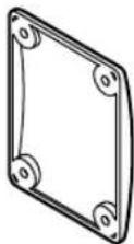
- M4×12 truss head tapping screw, 4 × 2 sets *Used for attaching the connector cover.
• Fall prevention wire, 1 × 2 sets
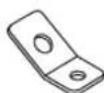
• Hook for fall prevention wire, 1 × 2 sets
• Bracket for fall prevention wire, 1 × 2 sets
- M6×14 Pan head screw with captive washer, 1 × 2 sets *Fall prevention wire installation screw
- Bracket cap, 2 × 2 sets *Used for attaching without the use of the standard U-bracket.
- M6×12 Countersunk bolt, 2 × 2 sets *Used for attaching the wire cap.
• Precautions for use, 1 unit



Installation and Connection
WARNING
• Make sure that the wall or ceiling where you are installing the speaker is strong enough to support it.
- Use screws that are appropriate for supporting the weight of the loudspeaker.
CAUTION
• Supported wire diameter: 12 AWG to 22 AWG
- The walls and ceiling will resonate with loudspeaker output, causing impaired sound quality, so reinforce the wall or ceiling sufficiently.
- When you install the loudspeaker vertically, install it with the terminals facing up.
Attaching the U-Bracket to a Wall or Ceiling
1 Turn the U-bracket knob screw ① counterclockwise to remove it and then remove the U-bracket ② from the loudspeaker.

2 Use the round holes ① at two places on both ends of the back and attach the U-bracket to the wall or ceiling.
By passing the speaker cable through the hole ② in the center of the U-bracket, you can route the speaker cable in such a way that it does not stand out.

Attaching the Fall Prevention Wire to the Speaker
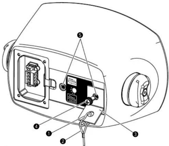
1 Pass the loop at one end of the fall prevention wire ② and the smaller hole of the bracket for safety wire ③ through the hook for safety wire ①.
2 Pass the M6×14 pan head screw with captive washer ④ through the larger hole of the bracket for safety wire ③ and then attach the fall prevention wire to one of the two M6 nuts ⑤ on the back of the loudspeaker.
Fastening torque: 2 to 3 N·m

WARNING
Make sure to take fall prevention measures.
Connecting and Setting the Input Selection Switch
This section describes how to connect the loudspeaker to a power amplifier or other speakers. The connector of this loudspeaker consists of four terminals; terminal 1 of the loop through terminal is "+" , terminal 2 is "+" , terminal 3 is "-" , and terminal 4 of the loop through terminal is "-". Terminals 1 and 2 and terminals 3 and 4 are connected inside the loudspeaker, respectively.
Parallel connection
Even if one speaker has a problem, other speakers will work fine. As shown below, connect the cable to the next speaker using the same terminal used for the cable from the previous speaker.
![graph TD A["Power amplifier or previous speaker"] --> B["+"] C["Next speaker"] --> D["+"] B --> E["Euroblock connector"] D --> E E --> F["Speaker"] E --> G["Speaker"] E --> H["Speaker"] E --> I["Speaker"] E --> J["Speaker"] E --> K["Speaker"] style A fill:#f9f,stroke:#333 style C fill:#f9f,stroke:#3…](/content/2026/05/1128157/images/60313c4c48f4ec5ee8bbb2827b3218087269e5fc3ed4f9ec17b7a1a465c1f1b5.jpg)
Loop through connection
With this connection method, it is easier to identify which speaker is experiencing trouble. If the Euroblock connector is disconnected from a speaker, subsequent speakers will no longer operate. Connect the cable from the previous speaker to the IN "+" (terminal 2) and "-" (terminal 3), and connect the cable to the next speaker to the loop through "+" (terminal 1) and "-" (terminal 4).

1 Strip away about 7 mm (0.3") of the insulation on the end of the speaker cable, insert the core wire of the speaker cable into each terminal of Euroblock connector ①, and tighten the screw ② to secure it.
The Euroblock connector is attached to the speaker's terminal at the time of shipment.


CAUTION
Twist the core wires of the speaker cable firmly so that the core wires do not come into contact with each other. This causes failure of the loudspeaker or power amplifier.
2 Insert the Euroblock connector ① into the rear socket, fit the speaker cable into the groove ③ from above the sealing cushion ②, and attach the terminal cover ④ using four M4 x 12 truss head tapping screws ⑤.
Fastening torque: 2 to 3 N·m


CAUTION
Up to 3.5 mm thick wire can be passed though the groove ③. If a wire with a thickness larger than that is passed through, the terminal cover ④ may be deformed, possibly causing failure of the drip-proof function.
3 Remove the input selection switch cap ⑥ on the back of the loudspeaker, use a flat-bladed screwdriver to turn the input selection switch ⑦ on the back of the loudspeaker, and then select the transmission method (100 V / 70 V / 8 Ω) and input wattage.
| CM-S58T CM-$56T CM-S54T | ||||||
| 70 V 100 V 70 V 100 V 70 V 100 V | ||||||
| A 7 | 5 W 15 W | 7.5 W 15 W | 3.75 W 7.5 W | |||
| B 15 | W 30 W | 15 W 30 W | 7.5 W 15 W | |||
| C 30 | W 60 W | 30 W 60 W | 15 W 30 W | |||
| D | 60 W | --- | 60 W | --- | 30 W | --- |
| E BYPASS 8Ω | ||||||

CAUTION
Adjust the E position only when combined with a low impedance amplifier. An incorrect setting could cause a failure of the speaker or power amplifier.

WARNING
When performing this procedure, make sure to first turn off the power amplifier.
Attaching the U-Bracket to the Loudspeaker
1 Set the loudspeaker inside the U-bracket ①, tighten the U-bracket knob screw ② from the top and bottom to temporarily secure the loudspeaker, and then tighten the hexagon socket head cap screws at the center of the U-bracket knob screws.
Fastening torque: 2 to 3 N·m

2 Secure the other end of the fall prevention wire attached to the loudspeaker to the wall or ceiling.
3 If you install the loudspeaker sideways, rotate the badge orientation as needed.
The badge can be rotated.

WARNING
- The knob of the knob screw for the U-bracket is for temporary fixing. For permanent fixing, use a torque wrench to adjust the torque of the hexagon socket head cap screw and then fix it in place.
• Fix the fall prevention wire on the building at a height where the loudspeaker or U-bracket will not hit a person in the event of a fall. - Secure the fall prevention wire on the building at a location different from where the U-bracket is secured on the building.
Installing the Loudspeaker Without a U-Bracket
1 If you install the loudspeaker on a wall or ceiling using the two M6 nuts on the back without using the supplied U-bracket, remove the U-bracket from the loudspeaker according to "Attaching the U-Bracket to a Wall or Ceiling" procedure, and then use the supplied bracket cap ① and M6×12 countersunk bolt ② to attach the fall prevention wire ③ to the top or bottom surface. Attach the wire in the direction of the back of the loudspeaker and then align the notch on the bracket cap with the wire.
2 By attaching the bracket cap ① in the same way on the side where the wire is not attached, you can achieve a neat appearance.
Fastening torque: 2 to 3 N·m


WARNING
- When installing the loudspeaker on a wall or ceiling, make sure the loudspeaker is supported in two or more places.
- When installing the loudspeaker using the two M6 nuts on the back, use screws that have a thread engagement length of 10 to 14 mm with the nuts.
- When using mounting fixtures other than the supplied accessories, make sure that they can sufficiently handle the weight of the loudspeaker.
- Be sure to check that the M6×12 countersunk bol② passes through the loop at the end of the fall prevention wire③.
Other
Specifications
| CM-S54T CM-S56T CM-S58T | ||||
| Loudspeaker Type | Two-way passive, reflex-loaded | Two-way passive, reflex-loaded | Two-way passive, reflex-loaded | |
| Frequency response(- 10 dB, Typical) | 95 Hz – 20 kHz 80 Hz – 20 kHz 53 Hz – 20 kHz | |||
| Sensitivity (1 W / 1 m) 87 dB 88 dB | 91 dB | |||
| Nominal Impedance 8 Ω 8 Ω 8 Ω | ||||
| Power Handling (RMS*1/ Program) | 40 W / 80 W 60 W / 120 W 90 W / 180 W | |||
| Transformer taps | 70 V 30 | W / 15 W / 7.5 W / 3.75 W 60 W / 30 W / 15 W / 7.5 W | ||
| 100 V 30 | W / 15 W / 7.5 W 60 W / 30 W / 15 W 60 W / 30 W / 15 W | |||
| Dispersion | 120 °H × 120 °V | 110 °H × 110 °V | 100 °H × 100 °V | |
| Maximum SPL*2 | 109 dB (peak) | 113 dB (peak) | 117 dB (peak) | |
| Driver configuration | LF | 4.5" (114 mm) cone | 6" (152 mm) cone | 8" (200 mm) cone |
| HF | 1" (25 mm) silk dome tweeter | 1" (25 mm) silk dome tweeter | 1" (25 mm) silk dome tweeter | |
| Connector | Euroblock (4 pin) × 1(input: +/- loop-thru: +/-) | Euroblock (4 pin) × 1(input: +/- loop-thru: +/-) | Euroblock (4 pin) × 1(input: +/- loop-thru: +/-) | |
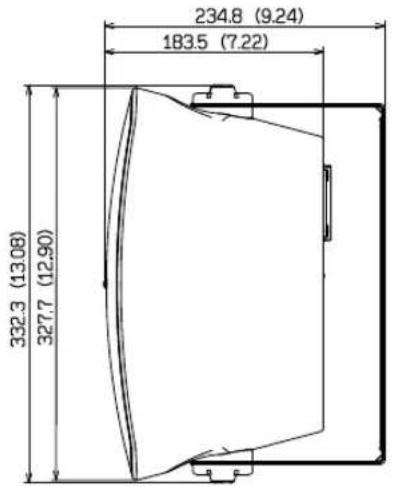
| Dimensions (W x H x D) | 154.9 × 250.6 × 144.5 mm(6.10" × 9.87" × 5.69") | 214.1 × 332.3 × 183.5 mm(8.43" × 13.08" × 7.22") | 282.0 × 457.8 × 252.4 mm(11.10" × 18.02" × 9.94") | |
| Weight (1 loudspeaker including the U-bracket) | 3.4 kg / 7.5 lbs. | 5.1 kg / 11.2 lbs. | 7.5 kg / 16.5 lbs. | |
| Rigging & Hardware | 1 × supplied U-bracket2 × M6 threaded mounting points on rear | 1 × supplied U-bracket2 × M6 threaded mounting points on rear | 1 × supplied U-bracket2 × M6 threaded mounting points on rear | |
| Grill | Punched Aluminum | Punched Aluminum | Punched Aluminum | |
| Enclosure | PP | PP | PP | |
| Environmental | IP54 | IP54 | IP54 | |
| Color | CM-S54T-W : White,CM-S54T-K : Black | CM-S56T-W : White,CM-S56T-K : Black | CM-S58T-W : White,CM-S58T-K : Black | |
*1 IEC60268-5
*2 Calculated from the power handling and seisitivity
• The specifications and design of this product are subject to change without notice.
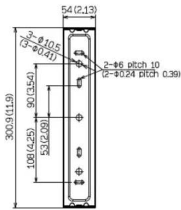
Dimensional Drawings
(Unit : mm (inches))
CM-S58T

CM-S56T
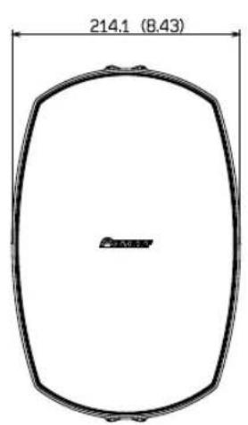
CM-S54T


© 2020 AlphaTheta Corporation. All rights reserved.
AlphaTheta Corporation
6F, Yokohama i-Mark Place, 4-4-5 Minatomirai, Nishi-ku, Yokohama, Kanagawa 220-0012 JAPAN
AlphaTheta株式会社
AlphaTheta EMEA Limited
Artemis Building, Odyssey Business Park, West End Road, South Ruislip, Middlesex, HA4 6QE, U.K. TEL: +44-203-7617-220
AlphaTheta Music Americas, Inc.
2050 W. 190th Street, Suite 109, Torrance, CA 90504, U.S.A. TEL: +1 (424) 488-0480
- INSTALLATION AND INSTRUCTION MANUAL
- CM-S54T / CM-S56T/ CM-S58T
- INTRODUCTION
- READ BEFORE USE (IMPORTANT)
- [FOR AMERICAN USERS AND CANADIAN USERS]
- THE SAFETY OF YOUR EARS IS IN YOUR HANDS
- ESTABLISH A SAFE LEVEL
- BE SURE TO OBSERVE THE FOLLOWING GUIDELINES
- [FOR EUROPEAN USERS]
- WARNING
- INSTALLATION
- ONLY THE WORKERS INSTALLING THE LOUDSPEAKER SHOULD BE NEAR IT DURING INSTALLATION
- TIGHTEN THE SCREWS AND BOLTS TO THE INDICATED TORQUE
- WHEN INSTALLING THE LOUDSPEAKER ON THE CEILING OR A WALL, ENSURE SAFE INSTALLATION BY CONFIRMING THE STRENGTH OF THE INSTALLATION LOCATION AND CHECKING THE INSTALLATION METHOD
- DO NOT INSTALL THE LOUDSPEAKER IN THE FOLLOWING ENVIRONMENTS
- WHEN INSTALLING THE LOUDSPEAKER OUTDOORS, MAKE SURE TO INSTALL IT AT A LOCATION AWAY FROM DIRECT CONTACT WITH RAIN OR SUNLIGHT, SUCH AS UNDER THE EAVES
- TAKE SNOW PROTECTION MEASURES
- USAGE METHODS
- BE SURE TO INSPECT THE LOUDSPEAKER AFTER AN EARTHQUAKE
- DO NOT OPEN OR MODIFY THE INTERIOR OF THE LOUDSPEAKER
- DO NOT PULL OUT OR INSERT THE CABLES WITH WET HANDS
- IMMEDIATELY STOP USING THE LOUDSPEAKER IF A PROBLEM OCCURS
- TO PREVENT A FIRE HAZARD, DO NOT PLACE ANY NAKED FLAME SOURCES (SUCH AS A LIGHTED CANDLE) ON THE EQUIPMENT
- DO NOT INSERT METALLIC OR FLAMMABLE OBJECTS INTO THE HOLES ON THE FRONT OF THE LOUDSPEAKER, AND DO NOT ALLOW THOSE OBJECTS TO FALL INTO THE HOLES
- DO NOT PLACE SMALL PARTS WITHIN REACH OF YOUNG CHILDREN
- CAUTION
- WHEN CONNECTING THE LOUDSPEAKER TO OTHER EQUIPMENT, TURN OFF THE POWER TO EACH PIECE OF EQUIPMENT
- CHECK THE STABILITY OF THE LOUDSPEAKER AFTER MOUNTING IT TO THE WALL OR CEILING
- DO NOT USE THE LOUDSPEAKER IN THE FOLLOWING STATES
- TURN THE VOLUME ALL THE WAY DOWN BEFORE TURNING ON THE POWER AND CHANGING THE CONNECTION
- DO NOT LISTEN TO THE LOUDSPEAKER AT HIGH VOLUMES FOR A LONG PERIOD OF TIME
- ALSO TAKE NOTE OF THE FOLLOWING CAUTIONS
- WHEN INSTALLING THE LOUDSPEAKER OUTDOORS, DO NOT USE THE LOUDSPEAKER BY TILTING IT UPWARD FROM THE LEVEL
- USE THE LOUDSPEAKER WITHIN THE SPECIFIED RANGE OF LOAD IMPEDANCE OF THE AMPLIFIER
- ABOUT HIGH-IMPEDANCE CONNECTIONS
- INSTALL THE LOUDSPEAKER IN ACCORDANCE WITH THE LAW
- ABOUT PROTECTIVE CIRCUITS
- CHECKING THE ACCESSORIES
- INSTALLATION AND CONNECTION
- ATTACHING THE U-BRACKET TO A WALL OR CEILING
- ATTACHING THE FALL PREVENTION WIRE TO THE SPEAKER
- CONNECTING AND SETTING THE INPUT SELECTION SWITCH
- PARALLEL CONNECTION
- LOOP THROUGH CONNECTION
- ATTACHING THE U-BRACKET TO THE LOUDSPEAKER
- INSTALLING THE LOUDSPEAKER WITHOUT A U-BRACKET
- OTHER
- DIMENSIONAL DRAWINGS
Brand : PIONEER
Model : CM-S54T
Category : Loudspeaker