
S4EXW - Pregnant PIONEER - Free user manual and instructions
Find the device manual for free S4EXW PIONEER in PDF.
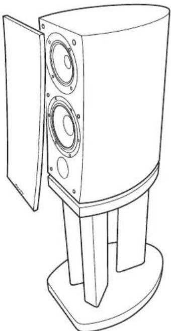
| Product Type | 3-way bookshelf speaker, bass-reflex, magnetic shielding |
| Brand and Model | Pioneer S-4EXW |
| Speaker Configuration | 3-way: 2 x 16 cm woofers, 14 cm midrange (cone), 3 cm tweeter (dome) |
| Nominal Impedance | 6 Ω |
| Frequency Response | 34 Hz – 100 kHz |
| Sensitivity | 85.5 dB (2.83 V) |
| Maximum Input Power | 160 W |
| Dimensions (W x H x D) | 263 x 490 x 387 mm |
| Weight | 20 kg |
| Diaphragm Materials | Tweeter: ceramic graphite; midrange: magnesium alloy; woofer: aramid/carbon composite |
| Key Technology | Coherent Source Transducer (CST) for a point source |
| Crossover Circuits | High-end components: air-core coils, non-inductive resistors, film capacitors |
| Supported Connections | Single-wiring, bi-wiring, bi-amping |
| Supplied Accessories | Decoupling spikes (4), bases (4), auxiliary feet (2), anti-slip pads (4), grille (1), instruction manual |
| Installation | On a solid, flat surface; use the decoupling spikes to optimize sound |
| Maintenance and Cleaning | Dry or slightly damp cloth with diluted neutral detergent; do not use chemical products |
| Electrical Safety | Disconnect the amplifier before connecting cables; load impedance 6–16 Ω |
| Usage Precautions | Do not expose to direct heat, do not sit on the speaker, avoid magnetic objects near the speakers |
| Country of Manufacture | Japan (Pioneer Corporation) |
| Collaboration | Certified by Air Studios (London) |
Frequently Asked Questions - S4EXW PIONEER
User questions about S4EXW PIONEER
0 question about this device. Answer the ones you know or ask your own.
Ask a new question about this device
Download the instructions for your Pregnant in PDF format for free! Find your manual S4EXW - PIONEER and take your electronic device back in hand. On this page are published all the documents necessary for the use of your device. S4EXW by PIONEER.
USER MANUAL S4EXW PIONEER
Register your product at:
http://www.pioneerelectronics.com (US)
http://www.pioneerelectronics.ca (Canada)
Thank you for buying this Pioneer product.
Please read through these operating instructions so you will know how to operate your model properly.
After you have finished reading the instructions, put them away in a safe place for future reference.
Contents
Before you start
What's in the box
About the EX series
Technology behind the S-4EX 4
CST. 4
Ceramic Graphite Diaphragm. 4
Magnesium Alloy Diaphragm 4
Bass Drivers 4
Bass Enclosure Construction 4
Crossover Networks 4
Collaboration with Air Studios 4
Installation and Placement
How to install 5
Installing the spikes 5
When not using the spikes 5
Choosing Where To Place The Speaker Systems 6
For U.S. model


Dear Customer:
Selecting fine audio equipment such as the unit you've just purchased is only the start of your musical enjoyment. Now it's time to consider how you can maximize the fun and excitement your equipment offers. This manufacturer and the Electronic Industries Association's Consumer Electronics Group want you to get the most out of your equipment by playing it at a safe level. One that lets the sound come through loud and clear without annoying blaring or distortion-and, most importantly, without affecting your sensitive hearing.
Sound can be deceiving. Over time your hearing "comfort level" adapts to higher volumes of sound. So what sounds "normal" can actually be loud and harmful to your hearing. Guard against this by setting your equipment at a safe level BEFORE your hearing adapts.
To establish a safe level:
- Start your volume control at a low setting.
- Slowly increase the sound until you can hear it comfortably and clearly, and without distortion.
Once you have established a comfortable sound level:
- Set the dial and leave it there.
Taking a minute to do this now will help to prevent hearing damage or loss in the future. After all, we want you listening for a lifetime.
Connections
Connecting to an amplifier. 7
Connecting the cables. 7
Single-Wire Connections. 8
Bi-Wire Connections 8
Bi-Amplification Connections 9
Other Information
Attaching/Removing the Grille Cover 10
Cleaning the speaker cabinet. 10
Specifications 10
We Want You Listening For A Lifetime
Used wisely, your new sound equipment will provide a lifetime of fun and enjoyment. Since hearing damage from loud noise is often undetectable until it is too late, this manufacturer and the Electronic Industries Association's Consumer Electronics Group recommend you avoid prolonged exposure to excessive noise. This list of sound levels is included for your protection.
Decibel
Level Example
30 Quiet library, soft whispers
40 Living room, refrigerator, bedroom away from traffic
50 Light traffic, normal conversation, quiet office
60 Air conditioner at 20 feet, sewing machine
70 Vacuum cleaner, hair dryer, noisy restaurant
80 Average city traffic, garbage disposals, alarm clock at two feet.
THE FOLLOWING NOISES CAN BE DANGEROUS UNDER CONSTANT EXPOSURE
90 Subway, motorcycle, truck traffic, lawn mower
100 Garbage truck, chain saw, pneumatic drill
120 Rock band concert in front of speakers, hunderclap
140 Gunshot blast, jet plane
180 Rocket launching pad
Information courtesy of the Deafness Research Foundation.


S001_En
Before you start
The nominal impedance of this speaker system is 6Ω. Connect the speaker system to an amplifier with a load impedance ranging from 6 Ω to 16 Ω (a model with "6Ω-16Ω" displayed on the speaker output terminals).
In order to prevent damage to the speaker system resulting from input overload, please observe the following precautions:
- Do not supply power to the speaker system in excess of the maximum permissible input.
- When using a graphic equalizer to emphasize loud sounds in the high-frequency range, do not use excessive amplifier volume.
- Do not try to force a low-powered amplifier to produce loud volumes of sound (the amplifier's harmonic distortion will be increased, and you may damage the speaker).
Caution: installation
- When placing this unit, ensure that it is firmly secured and avoid areas where it may be likely to fall and cause injury in the event of a natural disaster (such as an earthquake).
- Do not attach these speakers to the wall or ceiling. They may fall off and cause injury.
- Do not install your speakers overhead on the ceiling or wall. If improperly attached, the speaker grille can fall and cause damage or personal injury.
- Switch off and unplug your AV equipment and consult the instructions when connecting up components. Make sure you use the correct connecting cables.
Caution: in use
- Do not place the speaker on an unstable surface. It could present a hazard if it falls, as well as damaging the equipment.
- Do not use the speaker to output distorted sound for long periods of times. This can result in a fire hazard.
- Do not sit or stand on the speaker, or let children play on the speaker.
- Do not put large or heavy objects on top of the speaker.
- Do not place magnetic objects such as screwdrivers or iron parts near the tweeter or midrange. Since the speakers use strong magnets, the objects may be attracted, causing injury or damaging the diaphragm.
For U.S. model
WARNING: Handling the cord on this product or cords associated with accessories sold with the product will expose you to chemicals listed on proposition 65 known to the State of California and other governmental entities to cause cancer and birth defect or other reproductive harm.
Wash hands after handling
D36-P4_A_En
For European model
If you want to dispose this product, do not mix it with general household waste. There is a separate collection system for used electronic products in accordance with legislation that requires proper treatment, recovery and recycling.
Private households in the member states of the EU, in Switzerland and Norway may return their used electronic products free of charge to designated collection facilities or to a retailer (if you purchase a similar new one).
For countries not mentioned above, please contact your local authorities for the correct method of disposal.
By doing so you will ensure that your disposed product undergoes the necessary treatment, recovery and recycling and thus prevent potential negative effects on the environment and human health.
What's in the box


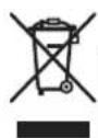
Spikes (with attached nuts) × 4


Spike bases × 4

Auxiliary feet × 2

Non-skid pads x 4
Grille x 1
Operating instructions
About the EX series
The EX series, incorporating the abundant technological know-how behind Pioneer's flagship TAD speaker series, was developed with the goal of creating the ultimate speaker possible in its price range.
The design and production of the EX series result from an international effort that represents the finest in Pioneer's speaker technology.
Technology behind the S-4EX
CST
The core driver of the system is the Coherent Source Transducer (CST), which draws on the technology used in TAD. The tweeter diaphragm is mounted concentrically within the apex of the midrange cone and provides a point source of sound from 400Hz to 100kHz . The CST ensures a perfect spectral balance between the direct and reflected sounds that arrive at the listener's ears, providing a more consistent sound throughout the listening room and improved imaging capability.
Ceramic Graphite Diaphragm
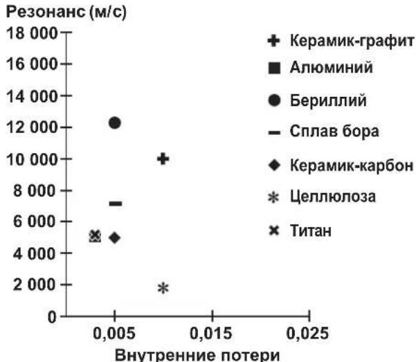
The CST's tweeter features a ceramic graphite diaphragm that provides top-level strength and dampening characteristics that are practically unrivaled by any other available materials currently used in high-end audio speaker systems. Ceramic graphite's lightness and exceptional strength combine to create speakers whose diaphragm resonance can be pushed far beyond their audible range.

Magnesium Alloy Diaphragm
The CST's midrange features a magnesium alloy diaphragm whose characteristic lightness and high inner loss provide excellent transience and minimal coloration of midrange sounds.
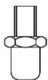
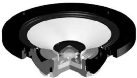
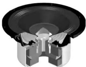
Bass Drivers
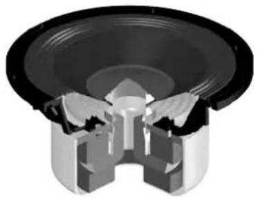
The bass driver pictured below serves as the foundation of the S-4EX speaker system. The driver's strength is the result of the Aramid/Carbon composite material, originally created during the development of the S-1EX, that is used in its diaphragm. Pioneer's exclusive LDMC magnetic circuit technology has been incorporated in order to preserve linearity from low to high output levels and minimize distortion.
Bass Enclosure Construction
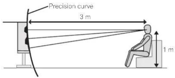
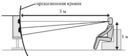
The unique form of the S-4EX is based upon logical necessity. In order to synchronize the arrival time of sound from the CST and the bass driver, each driver is mounted upon a baffle that serves to create a highly delicate curve known as the "precision curve" (see illustration below). Made of up to 65 mm thick MDF (Medium Density Fiberboard), this baffle is, moreover, strong enough to contain the force of the drivers. Additionally, the bass port has been carved out of an extremely thick block of MDF, resulting in the reduction of wind noise for clear, deep bass.
Crossover Networks
The crossover networks use only the finest components. Air cored coils, noninductive resistors, and film capacitors in the signal path are all carefully chosen and optimized for the CST driver to provide the greatest transparency to the signal. The bass drivers use silicon steel plate core inductors that minimize distortion and loss during energy transfer. All components are connected directly to their respective wiring materials, instead of a printed circuit board, allowing for minimal loss and maximum performance.
Collaboration with Air Studios
Since its establishment by George Martin in 1969, London, England's Air Studios has earned unequivocal respect from scores of artists who recognize it as the world's premier recording studio. The Air Studios seal that was awarded to the S-4EX indicates that these speakers are capable of producing the high-quality sound demanded by the world's top-class sound creators.

Installation and Placement
How to install
Please observe the following points when installing speakers: These speakers are bookshelf-type speakers. They will provide best performance when placed on a solid level surface away from the floor. If placed directly on the floor, reverberation will be amplified, producing a boomy, undefined sound. Ideally, the high-range speakers (tweets) should be placed at a height roughly the same level as the listener's ears. We recommend using the CP-4EX speaker stand for optimum sound and stability. When using the CP-4EX speaker stand, be sure to secure the speaker to the stand with the provided screws to prevent the speaker from falling.
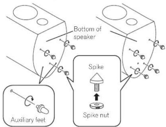
Installing the spikes
This speaker is provided with spikes and spike bases that should be used to produce optimum sound quality.
Installation
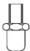
1 Attach the spike nuts to the spikes.
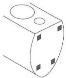
2 Twist the spikes into the threaded metal inserts (M6) embedded in the bottom of the speaker.
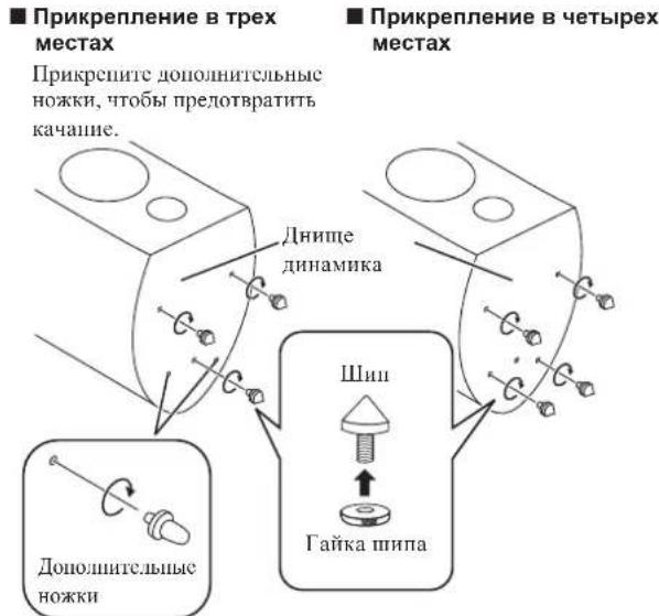
Consult the drawing and select either of the positions noted to fix the spikes.
■ Attached in three positions ■ Attached in four positions
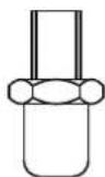
Attach the auxiliary to prevent rocking.
3 Set the spike bases in the positions where the points of the spikes will strike when the speaker is set down.
Place enough spike bases to match the number of spikes used.
4 Rotate the spikes to adjust their height, then rotate the spike nuts counterclockwise to fix the spikes at the adjusted height.
5 Set the speaker on the spike bases and adjust to be sure the speaker is level and does not rock.
6 When mounting the spikes in three locations only.
a) Rotate the auxiliary feet to adjust their height. Adjust the height so that about 1 mm to 2 mm of space remains open between the feet and the installation surface.
b) Rotate the spike nuts counterclockwise to fix the auxiliary feet at their adjusted height.

Caution
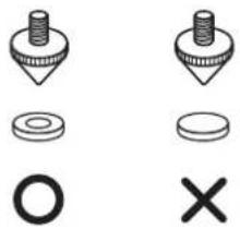
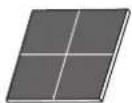
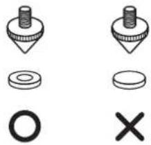
Always use the spike bases as shown, with the indented surface facing up to receive the spike point.
If you do not use the spike bases when placing the speakers, the spikes may cause damage to the floor. If you plan on using the spikes we highly recommend to use the spike bases.

Important
- As this unit weighs some 20kg , it is very dangerous to try and set the spike nut while tilting the speaker. Be sure to place the unit on a soft area (such as a blanket) so that it does not damage the floor, and carry out the installation with at least two people.
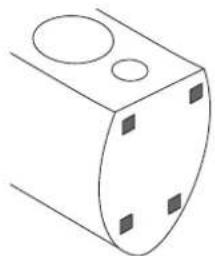
When not using the spikes
To assure stable installation, affix the non-skid pads to the bottom surface of each speaker.
Choosing Where To Place The Speaker Systems
Placement within the listening room will have a great impact upon the total performance of the S-4EX speaker system in terms of bass performance, tonal accuracy, and imaging. All rooms are different and so this section is intended as a guide only. Experimentation in your room will yield optimum results.
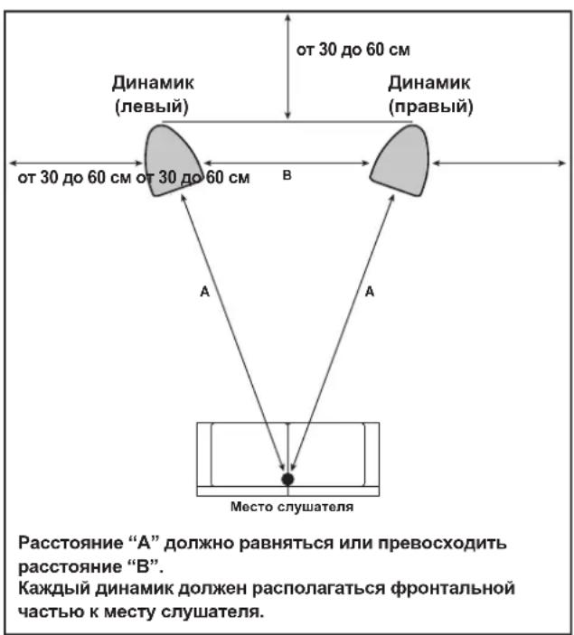
Use the graphic below as a guide to determine optimal speaker placement.

Distance "A" should be equal to or greater than distance "B." Each speaker should face the listening position.

Important
- Do not place the speaker where it will be in direct sunlight, and avoid positioning it near heaters and air conditioners. Doing so may cause warping and discoloration of the speaker cabinet and damage to the speaker.
- Pioneer assumes no liability whatsoever for damages resulting from assembly, improper mounting, insufficient reinforcement, misuse of the product, acts of nature, etc.
Connecting to an amplifier
This speaker does not include speaker cables used for connecting to an amplifier. Take the following factors into consideration when choosing speaker cables so that you can get the most from your speaker system:
- Use heavy-gauge speaker cable if possible, and keep the cables to the minimum necessary length.
- If the length of cable required for left and right speakers differs, use cables of the same length, matched to the longer distance.
- Cables have differing characteristics. Keep this in mind when using any cable.
- Select cables with as little resistance as possible, and make sure the cables to the speaker terminals and amp are firm and secure.
CAUTION
These speaker terminals carry HAZARDOUS LIVE voltage. To prevent the risk of electric shock when connecting or disconnecting the speaker cables, disconnect the power cord before touching any uninsulated parts. D3-4-2-2-3
Connecting the cables
1 Switch off the power to your amplifier.
2 Connect the speaker cables to the input terminals (lower) on the back of the speaker. For input terminal polarity, red is positive (+) and black is negative (-).
3 Connect the other ends of the cables to the amp's speaker output terminals (for more details, refer to your amp instruction manual).
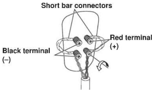
- Grasp the cap knobs on the lower input terminals and rotate them to the left (counter-clockwise), insert the speaker cable wires into the holes in the terminal posts, then tighten the knobs to secure the short bar as well as the wires.
- You can also connect the speaker's terminals with a banana plug. When using a banana plug, be sure to remove the cap at the tip of the input terminal.
- After connecting the plugs, pull lightly on the cables to make sure that the ends of the cables are securely connected to the terminals. Poor connections can create noise and interruptions in the sound.
- If the cables' wires happen to be pushed out of the terminals, allowing the wires to come into contact with each other, it places an excessive additional load on the amp. This may cause the amp to stop functioning, and may even damage the amp.
- When using a set of speakers connected to an amplifier, you won't be able to obtain the normal stereo effect if the polarity of one of the speakers (left or right) is reversed.
Single-Wire Connections
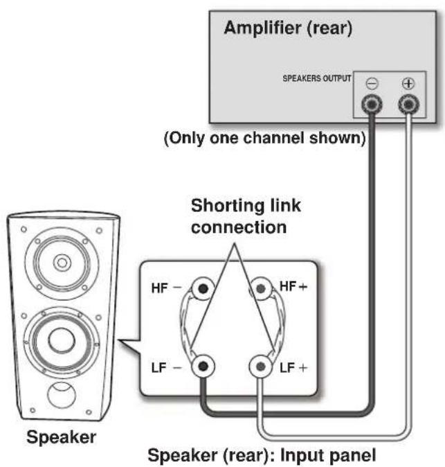
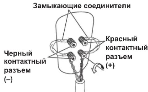
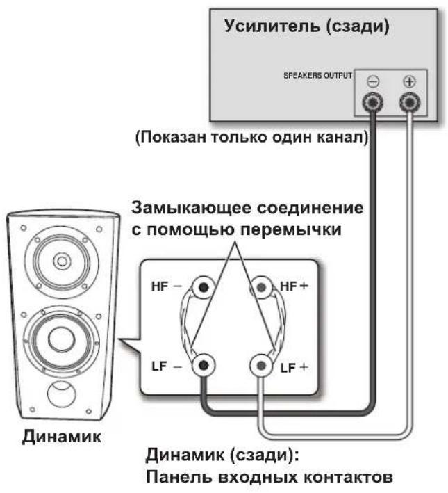
For single-wire connections, connect the mid-to-high- and low-frequency sections of the crossover network with the shorting link that was included with this unit, then connect the (+) wire from your amplifier to either red binding post and the (-) wire from your amplifier to either black binding post, as shown in below.
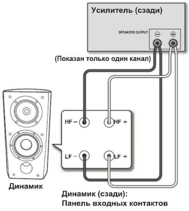
Bi-Wire Connections
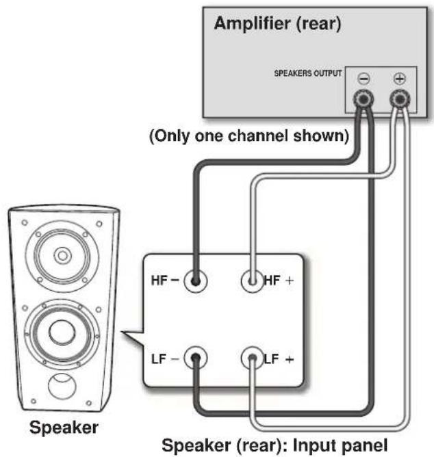
In a bi-wiring connection, you independently plug in the speaker systems running from the amp to their respective high- and low-frequency plugs. This results in the CST driver and bass drivers being independently connected directly to the amplifier, offering you the freedom to optimize the cable type for each of the drivers. Connect one set of wires to the bottom set of binding posts (bass driver-specific network). Then connect a second set of wires to the top binding posts (CST-specific network). Next, connect both sets of wires to the appropriate terminals on your amplifier. Take care to connect both (+) wires to the (+) amplifier terminals and both (-) wires to the (-) amplifier terminals, as shown below.
Bi-Amplification Connections
Bi-Amplification allows the best performance when using dedicated amplifiers for low- and mid-to-high-frequency sections. There are two possible configurations, commonly referred to as horizontal and vertical bi-amping.

Caution
Remove the shorting links before connecting speaker cables in bi-amplifications connections.
Failure to do so may result in damage to your amplifiers.
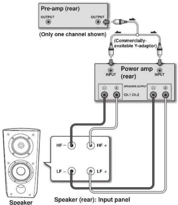
Vertical Bi-Amping
With this configuration, identical stereo amplifiers are used for each speaker system. One channel of each amplifier drives the low frequency section and the other channel drives the high frequency section, as shown below.
Connect one set of wires and amplifier channel to the bottom set of binding posts (bass driver-specific network).
Then connect a second set of wires and the other amplifier channel to the top binding posts (CST-specific network).
Take care to connect both (+) wires to the (+) amplifier terminals and both (-) wires to the (-) amplifier terminals.
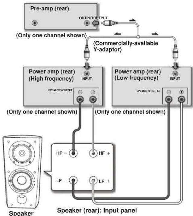
Horizontal Bi-Amping
With this configuration, you may use different stereo amplifiers for the low- and mid-to-high-frequency sections of the speaker system (e.g., tube amplifiers for high frequency and solid state for low frequency). Each channel of one amplifier drives the low-frequency section of each speaker system and each channel of the other amplifier drives the mid-to-high-frequency section, as shown below.
This method requires that both amplifiers have the same gain; otherwise an imbalance will be heard between the low- and mid-to-high-frequency reproduction from the speaker system. If in doubt, please consult your local dealer.
Other Information
Attaching/Removing the Grille Cover
This speaker system comes with grille covers which may be attached and removed by:
1 To attach the grille cover, line up the holes on the speaker with the inserts on the grill, and press firmly.
2 To remove the grille cover, grab it by its bottom with both hands and gently pull toward you to separate the bottom part of the grille from the speaker.
3 Slide your hands up to the middle section of the grille, and once again pull gently toward you. This will remove the middle section of the grille from the speaker.
4 Finally, repeat this same motion for the top part of the grille, removing the grille entirely from the speaker.
Cleaning the speaker cabinet
With normal use, wiping with a dry cloth should be sufficient to keep the cabinet clean. If necessary, clean with a cloth dipped in a neutral cleanser diluted five or six times with water, and wrung out well. Do not use furniture wax or cleansers.
Never use thinners, benzine, insecticide sprays or other chemicals on or near this unit since these will corrode the surfaces.
Specifications
Enclosure Bass-reflex floorstanding type (magnetically shielded)
Configuration 3-way
Woofer. 16 cm (6 5/18 inch) cone x2
Mid tweeter .14 cm (5 1/2 inch) cone/3 cm (1 3/8 inch) dome Impedance 6Ω
Frequency response. .34 Hz to 100 kHz
Sensitivity 85.5 dB (2.83 V)
Maximum input power 160 W
Exterior dimensions 263 W mm x 490 H mm x 387 D mm 10³/8 W in. x 19⁵/16 (H) in. x 15¹/4 (D) in.
Weight 20 kg (44 lbs 2 oz.)
Supplied accessories
Spikes (with attached nuts). 4
Spike bases. 4
Auxiliary feet 2
Non-skid pads. 4
Grille .1
Operating instructions

Note
Specifications and design subject to possible modification without notice, due to improvements.
Magnetic shielding
This speaker system is magnetically shielded. However, depending on the installation location, color distortion may occur if the speaker system is installed extremely close to the screen of a television set.
If this happens, turn off the television, then turn it on again after 15 min to 30 min. If the problem persists, place the speaker system away from the television set.

is a trademark placed on a product with Pioneer's Phase
Control technology. This technology enables high-grade sound reproduction through each component by improving overall phase matching.
Published by Pioneer Corporation.
Copyright © 2008 Pioneer Corporation.
All rights reserved.
AFTER-SALES SERVICE FOR PIONEER PRODUCTS
Please contact the dealer or distributor from where you purchased the product for its after-sales service (including warranty conditions) or any other information. In case the necessary information is not available, please contact the Pioneer's subsidiaries (regional service headquarters) listed below:
PLEASE DO NOT SHIP YOUR PRODUCT TO THE COMPANIES at the addresses listed below for repair without advance contact, for these companies are not repair locations.
AMERICA
PIONEER ELECTRONICS SERVICE, INC.
P.O. BOX 1760, LONG BEACH, CA 90801-1760, U.S.A.
CUSTOMER SERVICE HOTLINE:1800421-1404
EUROPE
PIONEER EUROPE NV
EUROPEAN SERVICE DIVISION
HAVEN 1087, KEETBERGLAAN 1, B-9120 MELSELE, BELGIUM
ASEAN
PIONEER ELECTRONICS ASIACENTRE PTE. LTD.
SERVICE DEPARTMENT
253, ALEXANDRA ROAD #04-01 SINGAPORE 159936
JAPAN AND OTHERS
PIONEER CORPORATION (HEAD OFFICE)
CUSTOMER SUPPORT CENTER
Bi-amplification vertical
Publication de Pioneer Corporation.
© 2008 Pioneer Corporation.
Copyright © 2008 Pioneer Corporation.
Woofer 16 cm conus x2
Copyright © 2008 Pioneer Corporation.
Copyright © 2008 Pioneer Corporation.
Entre 1960, a few students were recruited to the Universidad de Buenos Aires. In 1972, they joined the Universidad de Buenos Aires (UNAM) and started working in the field of design and production. Since 1983, they have worked in the fields of design and production.

AIR STUDIOS
Instalacao e Disposicao
Como instalar
"Copyright" © 2008 Pioneer Corporation.
Copyright © 2008 Pioneer Corporation.
Kopiering forbjuden.
Copyright © 2008 Pioneer Corporation.
Anti-gifelt × 4
Grill x 1
Bruksanvisning
Hvis du onsker á kaste dette produitet, ma du ikke blande det med vanlig husholdningsavfall. Det finnes et separat innsamlingsystem for brukte elektronikkprodukter, som i henhold til lovgivningen krever korrekt specialbehandling, gjenbru k og gjenvinning.
Spike (med paskrudd mutter) 4
Spiketabletter 4
Stttefot 2
Anti-glifelt 4
Grill 1
Bruksanvising

Merk
Opphavsrett © 2008 Pioneer Corporation.
Alle rettigheter reservert.
Copyright-oikeudet © 2008 : Pioneer Corporation.
BlaorapnBac3aIOkyIkyH3JIHHKOMIIaHHPioneer.
TIOKJIyIcTa, O3HAKOMbTEcB c HactoIe iHCTpyKIuei IIO 9KCIlyaTAlHH, YTO6bI y3HaTb, KAK IIpaBILbHO 06paIIaTbC C npHO6peTeHHo BAIM MOIDJIbIO.
Toro, KaBb 3aKOHHTe O3HaKOMJIeHHe C HcHTpyKlueH, CoXpaHHTe ee B HAdekHOM MecTe IIO6paIIeHn K He B 6yIiE.
CopepxaHne
Ipeed nayanom 3Kcnnyatauun
KoMnJIeKT nocTaBKn
O cepuEX
TexIOIOHN BOCIOBE S-4EX. 4
CST 4
KepamHK-tpaHToBaMm6pHa. 4
Membpua H3 cuiaba marHH 4
Hn3KoactOTbIe npaiBepb4
BcIpoCHHbIe Hn3KoayactOTHbIe IpOMKOFOBOpHTeJIN 4
Pa3neHHTe.1bHbIe 0nTbp5 5
Pa3pa60kn B c0rpduuuecTbe c Air Studios 5
YctaHObKa pa3MeueHne
IpaBnla yctanOBKn 6
YCTAHOBKa IIIIOB 6
EeH HnHb He Hcno.1b3yIOrca.. 6
Bb6op MecaIpaMaMeHnHa kyeyHeecknx ChcTcM 7
CoeHHnHn
IooeHHHeHKeYehJIHTeJIO 8
PioknueHne ka6eien 8
OIOIOPOBOIOIIbc coeHHHnH 9
BByxnpoBOHbIe coeHHHeHH 9
CoeHHHeHH B cxMe C IByXkHaIbHbIM yCHHeHHem 10
Dpyra INHopmaua
YcTaIOBka/chrTHpeWetKN DHHAMHKA. 11
HCTKa KOpIyca HHaMHaKa 11
TexHHueckHe xapaKTepeHCTHKn. 11
HOMHIIaIbIIOe IIOIIIOoe COIpOTHHBJIeIHHe dAIHIHOAkyCTHueckOH CHCTEMH COCTABJIET 6Ω, PIOcEOJIHHIe TAEKCTHIECKYIO CHCTCMY TOIbIK K YCHJNTCJIM C IOJIHHM COIpOTTHBJCCHNCM HAPy3KN BIPeJIeX AOT 6 Ω IIO (MOEJIH, IIa BIXOJIHHX KOHTAKXT HA DnHAMIK KOTOPBX YKA3HO “6Ω-16Ω”
B ⅢEJIXIpeIOITbpaIIHINIOBpeKdIIHINaKcYCTNecKOCHcTeMBBpe3yJBtATEBXOHOHIEpeIpy3KNIOKaIHyTc,co6HOaHTC CJIeIyIOHMe MPBIpeIOCTOPOKIOCTH:
He IyckaIte Hauhy Ha aykyeHcyckyo ChcTcMy cHHTAIOB, MOIOCTb KOTopbIX IpeBbIIaET 3HaueHHe MaKCHMaJIHO IOUYCTHMo MOIOHCTH HbXOJe.
Ipn HcnoB3OBAHHrpaHneckoro KBaJIaHepaIbIeJIINB 3ByaHnrrpOMKHX 3BYKOB B BbCOKOaCTOTHom DHaNA3OHe, He yctAHABJINBAHTe Ha ycH.IHTeJepe3MePHo BbICOKN yPOBCHB rPOMKOCTH.
HepeperpykaIteMaIOHmBuYcHHTeJIb, bHTaRc HOBbcHtB yPOBEH rPOMKoCTN 3ByuAIIHn (rAPMOHHueCKOE HcKaKeIIHe yCHINTeJIy YBCINHHTeR n 3TO MOKcET IOBpcHITb DHHAMNK).
BHHMaHHe: yCTaHoBka
YCTAIIABINBAIyCTPOIECTBO,y6eIHTEcB TOM,HTOIOIaEKIO 3aΦHKCHPOBAHO HA CBOEM MecTe. H36eraTte TaHX MeCT pa3MeiChH,B KOTOPbIX OHO MOKCT yHaCTb H IIPHHITb TpaMbB B cIpyae CTXHNIOFO BeCTBHIAIIPHMep, pH NcMJEtpCeIHIN).
He 3akpenIJIHrTe 3TH JINHAMHKn Ha cTeHe HJN HOTOLKE. OHN MOryt ynaCTb H npHnHHTb TpaBMy.
He y cTahAHINBAHTE HAMHKn HAI TOIOBOH Ha IOTOJIke HJIN Ha CTHe. IIpH HeipABHHOBHM HJIN HEHaJEKHOM KpeIIeHHN peIeTKA HAMHKa MOKcET YIacb, TTO MOKcET CTAb IIpHUNHOI IOBpeKJIIHH O6OpYIOBAHIN HJIN TpaBM.
- PnHIOeEHHeHHKOMIOHOHTOB, BbIKHOaHTe HOTCOeHNHBAaueyHO-/BnDCOObopyoBOAHNE H3 PO3CTKN, YHTaHTe HcoIHOaIte BCE HHCTpyKHH. Y6eIHITecb TOM, YTO BnHCIOJIb3yeTe IpABINbHbe COeHNHtEJIbHBe Ka6eHH.
BHMHHe: BO Bpem3KcPnIyatauN
He pa3MeIaIte DHHAMHK Ha HeycToHbOIOBepxHocTH.
PiJeHHe DHHAMHK MoKcT CO3dABaTB OAnChOCTH JINHOe, a
TAkKe CtAIBPCHHOH IOBpcKJHIIHOOBpyOBAHN.
He IONYcKaIte BBBOI uepe3 HnHAMHK cKaKeHHOro 3BykaB TcHHe DCHTCJbHO rHPOHa BpemH. 3TO MOKCT CO3aBaTb OAnachoctBo3rOpAHn HIOkapa.
He caJITcB Hc BCTaBAHTe Ha JINHAMK, a TaKc He HO3BOJHrTc JEAM HpTaB HJINAMHKe.
HeHOMeHnAHTHe HnHaHmK 60bHnE HnTn TnKeJIbe IpeMeTb.
IHe IOMeHaiTe pRdOM C BbICOKOaCTOTHBIM HIN CPcIHcHAcTOTbHM INHAMKOM MaHHTHBHC M CTaJIINHcCKHC IpEIMtBu,IIpHmep,OTBepTKy.IOCKoJIbKY B IIINAMHKAX HCIOJIb3yOTc CHJbHbIE MaHHtBu, OHN MOrY PnHTAHBaTb TaKHe 06bKeTb, YTO MOKeT cTaB IIpHnHIOI TpaBMb HIN IOBpeHITb MEM6paHy.
KoMnJIeKT NOCTaBKn


IIHHbI (c npHKpcILCHHbIM raKamH) x 4


OCHOBaHHH HHOHBx4
DIOHOHHTBHLBHe HOKKn X 2
IpeoxpaHHTeJIbIbHe HeckoIb3KHe NoIaIaKn x 4
Pcicka x 1
HctpyKINn no 9KnjIyataaun
Ecnn Bbl JxnaeTe yTINn3npoBAtb DaHnoe H3dEne, He Bbl6paCbIBaTe erO BMcTe C 06bHbIM 6bITOBIM MycopoM. CyIecTByet OTdeNbHa CnCTema C6opa NcNtob3oBaHHbx 3NeKtpoHHbx H3dEIn B COOTBeTCTBm C 3aKHOaTeJIbCTBOM, KOTopar npednonaraet COOTBeTCTByIOuee Obauen, Bo3bpA n nepepa60Ky.
Yacthble kInnehtb-BrpaHax-Hehax EC, B UBeinapm HOpBernn Moryt 6ecnnaTHo Bo3Bpaaatb nCnObl3OBaHHbIe 3JektpOHbIe I3dEINBA COOTBTCTByIOUne NHyKtbi c6opai nn Dnepy (pni NOKynke CXoDHoro HOBOrO n3dEINIA).
B ctpaHax, He nepeucneneHbix Bblwe, dna nonyeHnIHphiOpMaun O npabInhbx Cnocobax ytnnnaoun obaaaintecb B COOTBETCTBHyUeueypeXdHn.
IocTynar TaKIM O6pa3OM, Bbl MoXeTe 6bITb YBepeHb I TOM, UTO yTINN3npyEmB INPOyKT 6dyET COOTBeTCTByIOUM 6pa3OM 6pa60TaH, nepeDah B COOTBeTCTByIOUm INpepea60Tan 6e3 BO3MOxHbIX HeratNBbIX NocNeDCTBIN DnA OKpyKaIOUe CpeBt N3DopOBbY JIoDei. K058 A
K058A Ru
O cepin EX
Cepur EX, eknouuea e c6e BCE MHOOoo6pa3ue mexhoonouyeckux docmukenu, eoonouenhhix e cepuu TAD, 032naesnoe u modehblp dduhamukoe npou3oocmea komnauu Pioneer, bila pa3pa6omaha c enbto co3daunaykycmuueckou cucmembi caMOO abcKOoO Knacca u3 EO3MOKHBIX daHHOM ueHOeOM duana3OHe.
H3aHH HcnoJIHeHHe IpoyKnn cepHN EX - 30 pe3yIbTat MekJyHapOINx ychHn HpeJIMBaHn LyHHX doCTHKeHH B o6JIactn AkyTHuecknx TexHOIOH KOpHApHn Pioneer.
TexHONORM N B OCHOBE S-4EX CST
B OCHOBC CHCTCMBI JCKHITexHOIOHCoherent Source Transducer (CST),pa3pa6oTAAIIA Hb6aTe TxIOIOH, HcIOJIb3yEmbIX B cepHH TAD.Me6paHa BbcOKOCACTOTHO rPOMKOROBOPHTeYcTAHOBJEA HaOIOH OCH C KOHYCOM cpcIHcHAcTOTHO DnHAMKa,co3JABAH ToeHHN IIcTOOHK 3ByKa B dHaIaHOte OI 400 IIO 100 KII. TexHOIOH CST 6cBcHcHBAET BCINKOCIEHHI cHcKtpaHbH b6aIanc MeKdy IprMaIMN HOTpaeKeHHBMN 3ByKaMHI,IOCTHrAOIHMH YIHN CUYIATAEJI,HTO IO3BOJIeR HIOUyath BoJee paBHOMepHOe 3ByAHNC IIO BCMeYMOHeIHOcEHNO IpocSyHHBaHH N yBCJIHNUHBAcT TOUIOCTb 3ByKOBOrO 6o6pa3a.
Kepamuk-rgaΦntoBaMm6paHa
BINHAMHKBeBICOKOaCToTHORAIIHnA3OHa Ha6a3eTexHOJrHN CST HIOJIb3yETcKepamHK-tpaHITOBaMmOpana,06ccNCHBaIOHaa BIBOCUAAHIN yPOBENbIPOuHOTn HdEMnHpOBAHIN,IPaKTHeCKn HEoCTNHMBnIJIIO6BXIpyTHNXHEMOIHxCMAtePnaHOB,CActO HIOJIb3yEMbIX cERoIIINB 6OIJIbHIHTCBIE IPOpeCCHOJAIBHX AkyCTHecKHX CnCTeM.CoehaTHNE JERKoCTN HckNJOHHTeJIbHOI IPOuHOCTN KcpAMo-tpaHHTaIO3BOJHCT CO3JABATb IIHHAMKn, pe30IIAC Mec6paIIH B KOTOPbX IOJIeepKHBae TIIHA3OII ayHOaCTOT JaIKKO 3a IpcIcJamH CJIbIMHOCTH.
MembapaH3 cPiaba MarHnA
BcpneactoTHOM HnHAMKc CST HcHb3yctcMm6paHa H3 CHIaHa MaHna, JIO KOTOPoro XapakTePbJIERKocHe BIIYTpEHHHe NToepH, YTO oBeecnHbAcT BeJIHKoJIeHIyIO IpeJaHy INpeJeBHnH3Koe HcKaKeHHe 3ByKOB cpeHaeactoTHOrO DnHaHa0Ha.
Hn3KoYacToTHbIe IpaNBepbbl
MoHHH Hn3KoHaCTOnHb IpaHep, H3O6paKeHHb BnH3y, CnyKHT OCHOB Bceh akyeTHuecko chTeMb S-4EX. MoHb OTOr OpaHBepa -pe3yJIbTAT hCNOJIb3OBAHINB Eero MEM6paHe KOMIOHTHO MATEpHAA HA OCHOBE apAMHla H yIepeOla, BIEpBBc pa3paObaTAnHO B IpoUeCCC paObTI HaS-1EX. 9KcKIO3HBHaa TexHOJrHA LDMC (Linear Drive Magnetic Circuit), pa3paObaTAnHaa KopHApaHne Pioneer, HcNoJIb3yEtca cIeIbIO IOIDepKaiHHIHHHeIOCTH AMIIITHyDHO XapAKTEpHCTKN Ha Bcex YpOBHX MOIOCTN BbIXOJHO TcHHaJa -OT Hn3KHX DO BbICOKHX -MHHMn3aHHN HcKaKeJIHH 3ByKa.
BcTpoeHHbIe HN3KoOaCToTHbIe rPOMKOrOBopNTeJI
Cboeobpa3na fopma akycthuecko chctembS-4EX o6yocobHea IIOTHuecko Heo6xoHMOCTbIc. C cJIbIbO cHINXP0IH3aIIHN BpcMeHH DoCTnKHeHH IO CnyuataE 3Byka H3 CST H MOHORO IIH3KooactOTIOHO IpaBepa, BCE painBepy ycTaIOBJIeHb Ha OtpKaTeJe, KOtOpH IMeet fopmy upe3bluaHNO TOHK KpHBOH, H3BeCTHOK Kprecision curve"(IpeunHNOHAR KpHBAA)(cm. PCHyIOK Bn3y). H3rotOBNEIIH III MDF (Medium Density Fiberboard -fH6poJIIT cpEINH IIIOHTOCTH) ToIINHO JIO 65 MM, OtpKaTe bO6laAeT IOIOIIHTEbIO MoIIbIO, DCtatoUIOI IOTO TIObCIepKbHaTB IBHXUYO CHNJ DHHAMHKOB. KpOME TORO, O1BcPCTN DIA HIKKOACTOTHO HOIHyATcJIY BpC3AO H3 Upe3blauHIO TOICTORO 6JOKa MDF, YTO o6ecneHBAET yMeIHWeIIIE BCtpeHbIX IyMBo IIOCTnKHeHH YHCTOTO H Jy60KO 3ByuHNN 3BykOB IIH3KooactOTIOHO IHaHa3OHa.
Pa3deneIteIbHbIeΦnIbTpbl
Bpa3HeIHTeHbXh xfHbTpax HcHb3yOTcToTbKO KOMHOHEt b
BbICOaHIIeTO KJIACCA. KaTyuKn C Bo3UyHbIM cepDeHHKOM,
6e3HHyKTHBHepe3CTOpbH INIeHOUYHE KOHeHCaTOPb B
CHTHaBHOM KAJAE TIIaTeJIbHO HOIObpaHb H OHTHMHNPOBaHb I
HCIOJIb3OBAHIN C npaiBepaMH CST, YTO o6eNEuHBAET BeIHKOJIeHHY
HepdauHy HCHOTcy CHHaJIa. B MOUHbIX HN3KOAcT0THbIX dpaiBepax
HCIOJIb3yOTc HIIaKyTOpbCo CTaJIbHBM IIaCTHIyATbM
cepEHHKOM, KOTOpme IpEeJIbHO cHJKAOT HCKaKeHHe N IOTepH
PpH IpeJaue 3Heprn. Bce KOMIOEHTHN HmEOT CO6CTBcHHyO
COeIHINHTeJIbHYo IPOBOkY, a He IOIOcoEIHHOTcYepe3 NeaHTHyO
IIIaY, YTO IO3BOJIACT DO MHHMyMA COKpATNBOTcPH N
MaKCHMaJIbHO yIyUHITb paOoyHe KaeeCTBa.
Pa3pa60TKBcoTpynHuecTBe c Air Studios
OchOBaHHaJKopJcKemMapTHHOMB1969rIyBIOHOHe aHHHckaa3Byko3aHbBaIOuaa cTyHnaAirStudios BbCOKO 3apeKomeHIOBanace6eCpeHNIIHPoKO KpyraHCIOJIHTeJIe H IOJyHJaIIHPOKc npH3HaHne KaK BeUYHae 3Byko3aHbBaHOHaa CTyHnMnpa.EmLemaStAS,KOtopoIOTMeueHaakCyTHueCKa CHCTeMa S-4EX,CBHNCTbcHBCTByETOTOM,YTO3THINHAMHKCHOC6Hb BOCpOH3BOIDt 3ByuHHe BbCOVAHIero KAeCTBA,OTBeVaiOooec CAMBM CTporHM Tpe6OBaHm LyHHx IpofoecCHOHaJIbHbIX CO3dATcHc3ByKa MHPoBOI KJAcca.

AIR STUDIOS
YctaHOBka pa3MeueHne
Ppabnla yctaHOBKn
IpycTahOBKe DHHAMHKOB,IOKaJyHcTa,co6bIoJaHte CJeTyOIOJIe IpaBHa: DaHHbE IHHAMHK HpeCTabJIHOT CO60I 一 DHHAMK JINIKHKHOIOKN. OIN IIPOBBAIOCT CBOH HANUYUHNE
3KcIIyataaHOHbIE KaueCTBa, KOrda pa3MeJeHbI Ha TBepdoH N POBHOIOBEPXHOCTN HAIIOLOv.Pa3MeIHcHHe DHHAMKOB
HEIOcpeCTBEHHO HA IOYy YCHHT peBep6epaHIO, YTO pINBeET K IYIKOMY, HcHCHOMY 3ByaHnHO. B NCAJC INHHAMHK
BbICOKoAcTOTIO DHAIIa3OIIa CIEyET pa3MeIaTH bIa TAKOH BICOTc, YTObI OHp PACIOIarAJIbC hPi6JIHHTeJIbHO HA yPoBHe yIeH.IIg
06ecHCCHHN OITHMAlbHOrO 3ByaHnH y cToIyHBOCTN
peKOMeHyTeC HIOJIb3OBAtB CTouKy DHHAMHK CP-4EX. IIpy
HCIOJIb3OBAHH CTouKl DHHAMHK CP-4EX O63aTeJIbHO HADcKHO
IIpHKPeIIHITe DHHAMHK K CTouKe C HOMOJIbIO pINJIaRaEMIX B
KOMIIeKTE NOCTABKN BHHTOB, YTObI IIpeDIOBpATNTb IaDeHne
dHHAMHKa.
YCTAHOBKa WnIOB
JaHHbIHHAMHKIOCTABJIETcCIIHnAMHHOCHOBaHHMHIINIOB, KOtOpBIE CIEyET HIOJIb3OBAbT IIOI OeCEneEINHOITHMaJIbIHOKaeCTBa 3ByaHHN.
YcTaHOBka
1 PnPKpENrTaRkN uINoB K uINnAm.
2 BBePNHe 1IINbI B pe36oBbIe MeTaNnueckne BCTaBKn (M6), npeDycmOTpeHHbIe BOCHOBAHN DInHaMNka.
O6paTHTeCb K pncyHKy H Bb6epHrte OHy H3 yKa3aHHbIX N03HINKpeHCHN UHHIOB.
3 PacnoIoxKeTe OCHOBaHnue 1nnOB B no3nux, B KOtOpBle nonadT KOnCbI uINOB npu yctAHOBke dHaMnka. PaIOIOXKeHcTe IOCTATOHTHO C0JIHcCTBO OCHOB IHHIOB B COOTBCTBHN cKOHcETBOM HcIOJIb3yEmbIX IIHHOB.
4 NOBOPaHbA WnNbI, OTPeryNpyte Hx BbICOTy, a 3aTEM NOBepHnte raIKu WnNOB npOTNB YacBOB CTpeKN, 4TO6bl 3aΦHKcHPOBaTb WnNbI Ha OTPeryNpOBAHHO BbICOTe.
5 NocTaBbTe DNHaMnK Ha OCHOBaHnN WnNOB nOTperyIpyIte, YTO6bl DNHaMnK cTOrn PoBHO HKe KaayIcR.
6 Pn yctahOBKe WInOB ToIbKO B Tpex MecTaX.
a) Otperynpyte BbICOTy DOONHHTeHBix HOKeK, NOBOPaUNBa HX.
OtperyHpyTe BbICOTy TaMM O6pa3OM, TTO6bMeKJy HOKKoH yCTaHOBOUHOIOBEPXHOCTbO OCTaBAIOcB OKOJO 1 MM J0 2 MM CBO6OHHIOIPOCTpAHCTBa.
b) NopBepHnTe raKn WInOB npOTNB YacBOB CTpeKN, TTo6bl 3aФнСИрОВаТБ DOONHNTeJIbHbI E HOKKn Ha OTPeryNIpOBAHHO BbICOTE.

BHHMaHne
Bcerda HcnoIb3yHrte ochoBAHHIINIOB, KaK 3TO IOKa3HO Ha pucyhke, C bbiEMKO II, II, 6paIeHHO BBePx.
Ecni npyycTahOBKe dHnAMNKOB OCHOBAHNIINOB He NCNOb3yOTcR,TO WInbI MOrY NOBpeNTb NOn INCNOB3OBAHNI WnIOB HACToTeJIbHO peKOMeHdyETcN CNOB3OBAbO CHOBAHNI WnIOB.

BaxkHo
IIOCKOJIbky BEC DAIIIOHO yCTPOHCTBA COCTABJET OKIO 20 K, Hpe3BbMauH OIOACHO IIbTaTbCperyIINPObaTb RAky IIHHa, HAKIOHRA IPIHOTOM IINHAMK. O6BaTeJIbHo KIAIHTc yCTPOIHCTBO HA MIRKYIO IOBepXHOCTb (HaIPnMEp, Ha OJeAIO), YTO6BI He IOBPCNTB IOKpbITNC HOJA, N BblIOJIHHNTE CTO yCTAHOBKY KA MHIIMYM BIDBOEM.
Ecnnnbl He nCnoB3yOTcR
IIOOeocneHn yctoiHHBOCTn yctaHOBKn npHKpeHnTe KHNu KaKDOI OIIHAMKa IIpeoXpaHIHTeJIbIe IIECKOJIb3KHe IODKTAIDK.
Bb6op MeCTa Ipa3MeIeHn AkyCTuYeCKnx CnCTem
Bb6op meCTa yctAHOBKn B IOMeIeHN HPOcIyIHHBaHN OKa3bIBaET OIpomHOC BIIHHNC Ha KaueCTBO 3ByaHNN II paOoHC xapaKTEpHCTKN KAcYtHuecKo ChTeMb S-4EX, TaKHe Ka: 3ByaHnE 6acOB, ToHIOCTb Hepeaun ToHaJIbHOCTe H 3ByKOBOrO o6pa3. NocKoJIbky BCE HOMeIeHN HMCOT CBOH HINHBNyAIBbc OC Oo6ChHOCTN, DaHHbI pa3JeI pPeHa3Hauen, UH HcNOJb3OBAHNN TOJIbKO B KaeeCTBe ObIEero cIpaBOuHOrO pykoBOJCTBa. Bb CMoKeTe IO6HTBCr OITHMaJIbHOrO pe3yIbTaT, EKcIepHMeHHTpyr C yCTaHOBKO B BaIeH KOHAtC.
Hb3yTcB npHBcEHBM HJKe rpaHkOM JIN CnPAKBn HpN onpeJeHH OHTHMaJIbHorO MecTa paHIOJOKeHH NHaMHKa.

Baxkho
He pa3MeIaIte IINHAMK B MecTAX,IOIBepKeIIbIX BO3JeCTBIO IIpMIX JIyuei COJIHEuHOrO CBeta, a TAKKe H36eaiTe MeC T B6JHn HAIpcBaTeHcN KOHINHOHePOB. Hcc6JIHOChN ETOI OpaHJa MOKeT IIpHBecTH K DeOpMaHH N ObecuBeHbAHHo KopNyca DHHAMHKa HIN IOBpeKdEHNO DHHAMHKa.
KOMIIHII Pioneer IIIEcETOTBeTCTBEIIIOCTb IIO BO3MeIeIIIO KaKHx-JIN60 yobTKOB, IOHeceHHbIX Bpe3y.IbTaTe c6OpKN, IIePpABHJIbHO rMOITtKa, IIeIOCTaTOHIOrKOpeIeHN, HEPpABHJbHOH 3KnIyataHIN H3JIIN, ABJIeHN IIpnpObln T.Ⅱ
IopcoeHHeHne KucnInTeJIIO
K daHOMy dHHAMHy He npHaIarAOTcKa6eHIN HAMKa, HCIOJIb3yEmbI IIOIOcOeIHHeH K cyHHTeHIO. T06bIO oecHHTb KoppeKTHyIO paOToY cAmBc BICOCHe paBOHc XapAKTePHCTHK aKyCTHueCKoN CCHTeMbl, IIpH BBIbOpe Ka6eJeIN HAMIKOB IIHHMaHTe BO BHMaHHe CJElyOHNHe fakTopb:
IIO BO3MOKHOCTH,HCIOJIb3yIte Ka6eJIIN DHHAMHKa THIIa Heavy Gauge HMHIMALIBHO Heo6xOJHMoJ dHHbI.
EcnHnHaKa6eJe,Heo6xoHMmaI JnLeBOrHO npaBoro HnAMKOB,OTNtAcTc,HIOJIb3yNTc Ka6eHNODHaKOBO BHHbCOOTBeCTByIOeH 60Jee DHHOMy pacctOHHIO.
Ka6cJH HMCOT pa3HbC xapaKTEpHCTKN. PnBbOpc H 9KcIIpyaIHIN JIO6Oro Ka6eJI NOMHHe 06 NTOM.
Bb6hpaiTe Ka6eHc HAHMeHbIMM BO3MOxHbM COIPOTHBHeHEm, H BcerJa IPOBepaIte, YTO6bI Ka6eH, HOCoEJIHHHeMe K KOHTaKTHbIM pa3BeMaIMnHaAMnKa HycnINTeJ, 6bHIIIOPOHO H HAckHO 3aKpcIHCHb.
BHIMAHNE
EcIn CnCTema BKJIIOUOHEA, npNKoCNOBHeNc K KOHTaKTM rpoMKOrOBOpNTeJe ONACHO.Bo n36ekaHne ONaCHOCTH NopaxHeNr 3JIeKTPnuCeKNM TOKOM pRn NOkJIIOUeHNr INr OTKlIOUeHNr KaBeJe rPoMKOrOBOpNTeJe OTCoeDNHrTe KaBeJb PntAHn rpeXDe Yem npNKacatbcra K JIIO6bIM
Heu3OIpOBaHHbIM DeTaJIaM.
D3-4-2-2-3 A Ru
IopknHueHne Ka6eNe
1 BbiknIOHTe nITaHne ycunNTeIa.
2 NocoeHNHTe Ka6eJIN DnHaMNKA K BXoHbIM KOHTaKTHbIM pa3beMam (HXXHHe) Ha 3aDHeN NaHeN dHaMNka. POnIpaHocTb BXoHbIX KOHTaKTHbIX pa3beMOB o6o3Naayetc cneyUOUM o6pazom: Kpachbl - nOIOXHTeHbI (+), YepHbI - OtpuataTeHbI (-).
3 NopcoeHHnTe npytne KOHbI Ka6ene K BbIXoHbIM KOHTaKTHbIM pa3beMaM (Ha DnHaMnK) ycHnTEnJ (3a NoDpO6HbIM ONcAHmE m o6paauNTecb K INCTpyKuIm NO 3Kcnnyataun Baawero ycnntenJ).
B3aHbIKHa HINKHX KOHTAKTHbIX pa3beMax, IOBepHnTE HX BJEBO (IPOTHUB YACOBO CTpeJKN); BCTaBte IPOBODa Ka6JIa INHAMHKA BOTBpCTHBA KOHTAKTTHbIX KJIeMMAX, 3aTeM 3aTAHnTE RoIOBKH, YTOb3aΦHKcnpoBaTB Ka IIPOBODa, TAK N 3aMbKaHOHn COeHNHHTeJB.
ⅡIⅡOIOoeHHeHHK KOHTaKTHbIM pa3BeMaM HINHAMKa BtAKKe MoKeTe HCIOJIb3OBaTB BHJky IIITEkePHorO(6aIIaIOBORo)THJa. IIpy HcIOJIb3OBaHHBILIKH IIITEkePHorO THJa He06XIOHMOydaJIHTb TOIOIBKN C BXOJDHX KOHTaKTHbIX pa3BeMOB.
Iocne no1coeHHHeHH HHTeJe, cJrKa NotHnTe 3a Ka6JIH, TTO6bI y6eHTbcB TOM, TTO KOHbI Ka6JIe HaIEKHO 3aKeJIeHb B KOHTAKTHbIX pa3bEmax. IIOXoI KOHTAKT MOKcT CTb IIpHINHO BO3HHKOHeHH IyMOB II pOJaAHN 3Byka.
EICINIPOBOdaKa6cJIe6bMyTcIyauHOBbIDepHyTBn3 KOHTAKTHBx pa3BeMOB H BOITY B KOHTAKMeKdyco0N,TO BBIOCT Ype3McPIHyo JOIOJIHHTeJIbHyHO Harpy3KY Ha ycHNTEJ. 3TO MOKeT cTAb II pHiHHoC6oEB B paOte I daKe IIOJOMKn yCHNIIEJI.
KorIa BbIOJIb3yeTecB KOMIIIEKToM IHHAMHkoB, IOIcOeIHHeHHbIX K yCHINTEHO, Bb HE CMOKeTe IIOJYHTb HOpMaJIbHbI OofoKr CTpecoDooHnueCkOro 3ByaHHa, ccln IOIpaHOCTb IOJIIOHoeHHo OHOrO H3 INHaMHKO (JEBOrO HIN Ipaboro) H3MeHcHHa Ia O6paTHyIO.
OdHONpOBoDhBie coeINHeHn
IINBIOJIHHeHHOHNPOBOHbIX COEHHHeHH, COEHHHTe KOHTAKbI CCKHIN cpcIHHX H BILCOKHX qACTOT C KOHTAKTMH CCKHIN H3KHX HACTOT C IOMOIIbIO 3aMbIKAO IIIEPEMBIKH, BKIOOEIIHO B KOMIIJEKT IOCTABKN yETPOHCTBA, 3ATEM IOIOCoEHINTe IPOBOJ (+) OT YCHINTEK J OJOHO H3 KpaehbIX KOHTAKTHbIX KJIEMM, a IPOBOJ (-) OT YCHINTEJ - K OJOHO H3 YepbIX KOHTAKTHbIX KJIEMM, KAK 3TO IIOKA3AIO BHH3Y.
BByXpOBOHbIe COeINHeHnA
B IByxIpOBoHoi KOHfHyrpaunn AkyctHueckne ChcTeMHIOKIOOHaiOTc H3aBHNCbMMM COcIHCHHHM N OYCHINCTI KCOOBtCTBYIOHM BICOKOAcTOTHBM H3KOAcTOTHBMKoHTAeIM paBemAM. TaKM o6p3OM, JpaBBep CST INH3KOAcTOTHBM JpaBcpebI IOKIOHOAIOTc H3aBHcHMOHEIOcePCTBcEHNO K yCJHNTEJIHO, YTO IIpeIOCTABJIET BO3MOXHOCTbBbOpa ONTHMaJIbHO TIIHA Ka6JIa IIA KaKJOIO pAIBePA BOTeJIbHOCTH. IIOcoeHNHTeOHy npy IPOBOOB K HIXKHeI NaPEKoTAkTHBX KJIEMM (IeNb H3KoAcTOTHO JINHAMKA), 3aTEMIOCoeHNHTe BTOpyIO npy IPOBOOB K BepxIEH NaPe KOHTAeBHX KJEMM (IeNb CST). 3aTEM IOCoEOHNHTe O6c IpaBp IPOBOOB K COOTBETCBYIOHM KOHTAKTHBM pa3BeMaM HA ycHInTEJe.Co6IOaIte NOIpaHocTB: IOcOeHNHHeIte O6a IPOBOBa (+) K KOHTAeTHBM pa3BeMaM (+) Ha ycHInTEJe, a 06a IPOBOa (-) - K KOHTAeTHBM pa3BeMaM (-) Ha ycHInTEJe, KA 0TO IOKa3IIO BIN3y.
CoeINHeHnB CxemeC DByXkHaHbHbIM ycHneHnEM
IByxKaHbOe ychHeHHe (Bi-Amplification) no3BOJnE nOlyuHTb camoe BbcOKoe KaeCTBO 3BvuaHH np HcIOJIb3OBaHH OTJeIbHbIX ycHHTeJIe IIN CCKHH HHKHX HcKHH cpeAHX H BbcOKHX HcTOT.
CyIeCTByET IBe BO3MOKHbE KOHfHypaHIN. KOTOpMe O6bHuHO Ha3bHaOT «Ropn3OHTaJIbHaa CXema» II «BepTHKaJIbHaa CXema» IByxKaHaJIbHorO yCHiHn.

BHHMaHne
IpeHIOOeOHHeHHem Ka6eHJHHAMHKOB KOKhpyaHHJByXKaHaJIbHOrO ychJIeHHy JaJIHTe 3AmkaHOHHe IepcMbHKn.
Ieoc6HIOeHHe 3TOrO yKa3aHnMoKET pNpBcTH K IOBpeKJdeHHo ycHInTeJIe.
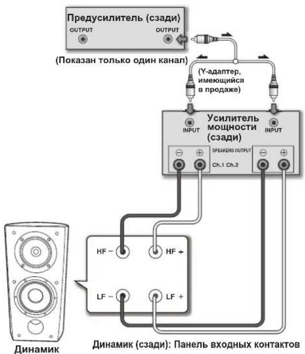
BepTKaJIbHaJa cxema DByXKaHaJIbHOro yCnJIeHnIa
B30I KOHpyaHH Jn KaJIOAkyCTHeCKO CHCTeMb HNOJIb3yOTc HJeHTNHybc yCHNTcH. OHH KAHAI KaKIOTO YCHNIIE NOIcoEINHaeTc K cekHH Hn3KHX qactOT, a npYrOi KaHaI -K cekHH BbOCHX qactOT, KAK 2TO IOKa3aIIo BHH3Y.
IIOcoeHINHTeOIIHyIAPy IPOBOOBKaHaJa yCHINTEJK HINKHHeI Iaep KOHTAKTHbIX KJIeMM (IcNb IIH3KOAcTOTHORO INHHAMKA).
3aTeM IOIcoeIHINHTBTOpyIO npy IPOBOOIBpyrTOKAIIIaYcHINCTK BepxHcHnApC KOHTAKTHbIX KJcEMM (ueHB CST).
Co6HIOdaIte IIOJIpaHocIb:IOIOcoEINHHIe Oba IIPOBOJa (+) K KOHTAKTHbIM pa3bEmAM (+) Ha ycHInTEJe, a 0ba IIPOBOJa (-) K KOHTAKTHbIM pa3bEmAM (-) Ia ycHInTEJe.
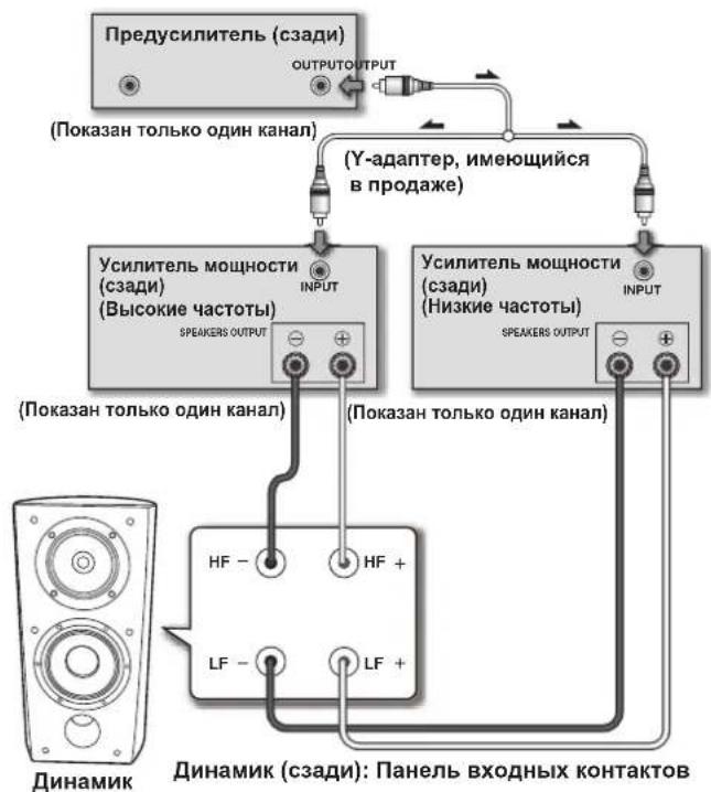
Topn30HTaBna Cxema DByXKaHaBbHorO yCInHeHn
B308 KOHfHypaHH Bb MoKTe HcHIOb3OBaTb pa3HHbIe ctepeoOHINHECKHC yCHHTCJIIN PA3cJIbHO IJIcckHH INH3KHX YACTOT H cekHH BbICOKHX YactOT aKcYCTHeCKO hCTEMBI (HaIIpHMEp, JAMIOBbY cHJITeJI b II bICOKHX YACTOT H IOJIpyBODIIHKOBbl YcHHTeJI bII HN3KHX YactOT).KaJbI KaHaJI OIHORO yChJHNTeJI HOJIKHOACTCR KHN3KOACTOH cckHH aKcTHeKCHCTeMb, a KaJbI KaHaJI dpyTOrO yCHHTeJI - K cckHH cpeIHIX N BbICOKHX YACTOT, KAK 3TO NOKA3HO BH3Y.
IpiH HIOJIb3OBAHHn DaHHoro MeTOda CoeIHINHn Hc06XoHmO, 106bI Oba yCHInTeJH HMeJH OINHAKOBH K0eΦHHeHT YCHJIeHn, B IipOTHBIOHM CIIyAc MEKJY IIHNKOaCTOTBIMH H cpeJIIE-H BcOKOaTcOTBIMN 3ByKaMn, BOcPiON3BOIDMbIMn AkyCTHeCKOH ChcEMoH, 6yET NaHIOJATbc JHC6aJHaC. Ecln y Bac NOBBtce KaKHe-JIb6o ComIIeHHn HIN BOpocB, 6paTHTEcb 3a KOiCyIbTaIIHeN K MeCTHOMy DIIepy.
YctaHOBka/CHrTne peWetkn DnHaMHKa
HaHHa akcTHueckKa ChTeMa NocTabIeTc CpeIeTKAM Ha HpeHHe HnHcHJ nnHAmHKa, KOTOpMC MOKHO CHrTB, BbIOJIHHB cIeMyOyIO OIIepaHIO:
1 4To6bI yCTaHOBnTb peWETKy, BblPOBnTe na3bI Ha KOJOnHe C BTyInKaMn Ha peWETke n c cnIOH HaxMMTe do ynopa.
2 TTo6bI CHrTb peWetKy, BO3bMITE ee 06eHN Mu pyKaMn 3a HNKHIOO YAcTb N OCTOpOXHO NOTHIne Ha Ce6y, TTo6bI OTDeINMb HNKHIOO YAcTb peWetKn OT KOJOnHKn.
3 IpeepBnHbTe pyKn B CpeDnHO YacThpeweTkn N eue pa3 octopoxKHO NOTAHNTE ee Ha Ce6ra. 3TNMBbl OTdEnIte cpeDnIO YacThpeweTKO T KOJOHKn.
4 Hakoheu, NOBTOPN TO Ke camoe Deuctbne IJI BepxHeu cactn pewetkn, noHIOCTbO CHMNTe pewETky C KOLOHKn.

Ynctka Kopnyca DnHaMHka
B 06bHbix ycIOBnX KcIHyatauHHIOctaTOHO IepHOuueckn IpoTHpaTb KopHcyxOyTKaHBQ, YTObIIOUepeKHBATb KOpNc B HCTOTc. PpH HCO6XoDHMOCTH, IpOTpAaTE TKAHBIO, CMOChHO HeITpAJIbHM MOIOIHm CpeCTBOM, pa36aBDEHHBM IINH IIIN IIIeCTH ActrX BOiB, H xopoHIO BHKaTOn. He IIObEyITEcb BOCOM HIN MOIOHNH cpcCTBaMH INI Me6CIN.
HkoTHe HIOJIb3yItecB pactBOpHTeJHM,6eH3HOM, HCCKTHINHbIMPiacbIHITCJIMH HIN JpyTHM XHHHCKHM BEIECTBaMH HA HIN pJDMOC DAHHBM yctpoHCTBM,IOCKOJIbKy 3TO BbIOBCT Koppo3HIO IOBepxioCTH.
TexHnueckne xapaKTepeNCTnKn
Kopnye HanoJIbHoro TnHa c OtpaKaTecEM 6acOB (MaHTHHOKpaHPOBaHHB)
KoHpya.. 3 noocb
IIH3KoyactOTbI HHHAMHK 16-cM KOHyc x2
CpeHHeacToTHbI HnHaMHK. 14cm KOHyc/3 cm Kyno
CoipotBJIeHne 6Ω
HactoTHaXapaKTepeHCTnKa 34TIO100K
YyBCTBHTeJIbHOCTb 85,5 AB (2,83 B)
MaKCHMAJIbHaB BXOTHaMOMIHHOCTb. 160Br
a 6 apHTIbIe pa3Mepbl.263 (II) MM x 490 (B) MM x 387 (T) MM
Bcc. 20K
IocTabIaIeMbIe B KOMnJIeKTe npHaIaJIeXHocTH
11Hb (c pRkpeHHbIMraKAM). 4
OchobHHKOHycOB 4
IOHOIHHTCJIbHbIC HOKHN 2
IpeoxpaHHTeJIbHbIe HecKOJIb3KHe NOJIaIKN 4
Peeetka 1
HctpyKnnn 103KcnIyataaun

3ameyaHne
TexHHueckHe xapaKTepeHCTHK H KOHcTpyKIIH MOrY MeHrTaBc8 6e3 IpeBaHPteJIbIHO yBeIOMJIeHH, B CBA3H C BHOCHMbIMH ycOBepIHcHcTBOBAHHM.
MarHnTHoe 3KpaHnPOBaHne
JaHnAkyCTHuecka ChcTeMa 3aHHeHa MaHHITbIM
3KpaHnPOBaHHem. OHaKO, B 3aBnCHMoCTH OT MecTa ycTaHOBKN, MOYT
BO3HNKaTb IBcTOBbc HCKaKeHH, CCJHn AkyCTHuecka ChcTeMa
ycTaHOBJIeHa cJHIIKOM 6JH3KO K 3KpaHy TeJIeBHOpa.
EeH 30 npOHET, BkIOHTe TJIEBHOp INBIOHTe eO CHOBa Hepe3 15 MHyT IO 30 MHyT. EeH pO6Iema coxpaHertc, Hepemctte akcytneckyio ChcEmy HoJaJIbIe OT TEeBH3opa.

BIBIECTC TOBAPHIM 3IaKOM,IIIOCHMbIM II IPOyKTb, B KIPMHMeHReTcTexHOIOHnpeYIpOBKn pa3bPioneer Phase DaHHAR TcXHOIOHn HO3BOJIeT HOUYaHTb
BbICOKOkaeCTBeHHoe 3ByaHHe BOCIPOH3BOHMbIX KaKbIM KOMIOHCHTOM 3ByKOIB IOCPCACTBOM IOBBIIICHI TOHOCTH HAcTpPOKH ypOBHa3HPOBKn.
H3daHO Pioneer Corporation.
Pioneer Corporation, 2008.
Bce npaba 3aHnnebl.
Pnmeyahne:
B COOTBECTBNN CO CTbEi 53aKoHa Pocncko Fepaun "O 3aunTe npab notpe6nte" YkasaHHe MnapTbeCTBa Pocncko Fepaun No 720 ot 16 nohra 1997 roda Kopnpauiae Pioneer Europe NV yctahabnaeYcnoBne Ha cneyohuy npdoonkntelbHoctb cpoka cnkybbl ophuaIbHO nocTabaBmX ha Pocnckn kpbHOK TOBABOB.
Aynno n Bndeoo6opyObaHne:7IeT
Pepenochoe aydnoo6opydoBaHne: 6 nT
Dpyroe obopyoBaHne (HayuHHKn, MmKpOoH nT.D.): 5 net
ABTomo6nJIbHa3JIeKToHnKa:6IeT
D3-7-10-6_A_Ru
銘謝購買日本先鋒公可產品。
Published by Pioneer Corporation. Copyright © 2008 Pioneer Corporation. All rights reserved.
PIONEER ELECTRONICS (USA) INC.
P.O. BOX 1540, Long Beach, California 90801-1540, U.S.A. TEL: (800) 421-1404
PIONEER ELECTRONICS OF CANADA, INC.
300 Allstate Parkway, Markham, Ontario L3R 0P2, Canada TEL: 1-877-283-5901, 905-479-4411
PIONEER EUROPE NV
Haven 1087, Keetberglaan 1, B-9120 Melsele, Belgium TEL: 03/570.05.11
PIONEER ELECTRONICS ASIACENTRE PTE. LTD.
253 Alexandra Road, #04-01, Singapore 159936 TEL: 65-6472-7555
PIONEER ELECTRONICS AUSTRALIA PTY. LTD.
178-184 Boundary Road, Braeside, Victoria 3195, Australia, TEL: (03) 9586-6300
PIONEER ELECTRONICS DE MEXICO S.A. DE C.V.
Blvd. Manuel Avila Camacho 138 10 piso Col.Lomas de Chapultepec, Mexico,D.F. 11000 TEL: 55-9178-4270
K002_Ru