MOF 001 - 1400 W - Router TRITON - Free user manual and instructions
Find the device manual for free MOF 001 - 1400 W TRITON in PDF.

| Product Type | Bi-mode plunge router |
| Brand | Triton |
| Model | MOF 001 (MOF001) |
| Rated Power | 1400 W |
| Supply Voltage | 220-240 V ~, 50/60 Hz |
| Max Input Current | 6.4 A |
| No-load Speed | 8,000 – 21,000 rpm |
| Speed Adjustment | 5 positions (1 to 5) |
| Collets | 1/4" and 8 mm |
| Plunge Stroke | 59 mm |
| Max Cutting Diameter | 55 mm (50 mm on WX7RT001 table) |
| Net Weight | 5.97 kg |
| Sound Pressure Level | 84.1 dB(A) |
| Sound Power Level | 95.1 dB(A) |
| Weighted Vibrations | 6.285 m/s² |
| Plunge Modes | Free plunge, winding handle, micrometric adjustment |
| Turret Stop | 3 adjustable feet for multi-pass cuts |
| Dust Extraction | Port for vacuum cleaner (Ø 38 mm) |
| Parallel Guide | Included with guide plate |
| Table Use | Possible (removable plunge spring) |
| Insulation Class | Double insulation (Class II) |
| Safety | Anti-kickback switch cover, spindle lock, depth stop |
| Maintenance | Accessible carbon brushes, regular lubrication, compressed air cleaning |
| Warranty | 12 months (online registration required) |
Frequently Asked Questions - MOF 001 - 1400 W TRITON
User questions about MOF 001 - 1400 W TRITON
0 question about this device. Answer the ones you know or ask your own.
Ask a new question about this device
Download the instructions for your Router in PDF format for free! Find your manual MOF 001 - 1400 W - TRITON and take your electronic device back in hand. On this page are published all the documents necessary for the use of your device. MOF 001 - 1400 W by TRITON.
USER MANUAL MOF 001 - 1400 W TRITON
Operating and Safety Instructions
Bedienings- en veiligheidsvoorschriften
FR Instructions d'utilisation et consignes de sécurité
DE Gebrauchs- und Sicherheitsanweisung
Istruzioni per l'uso e la sicurezza
ES Instruetiones de uso y de seguridad
Instruções de Operação e Segurarca
PL Instrukcja obstugi i bezpieczeste sta
RU IInchtpkykunn no 3Kcnpnyataunn npabuHa texhkn6e3onacHOCTN
Kezelési és
biztonsági utasítások
CZ Provozní a bezpečnostné poukyny
SK Prevádkové a bezpečnostné poukny
TR Calima ve Güvenlik Talimatlari

Designed in Europe


A

B
C

D
E
F

G
H

1
J

K
L
M

N

0

P
Q
R
s

T
U

V
Introduction
Thank you for purchasing this Triton tool. This manual contains information necessary for safe and effective operation of this product. This product has unique features and, even if you are familiar with similar products, it is necessary to read this manual carefully to ensure you fully understand the instructions. Ensure all users of the tool read and fully understand this manual.
Description of Symbols
The rating plate on your tool may show symbols. These represent important information about the product or instructions on its use.

Wear hearing protection
Wear eye protection
Wear breathing protection
Wear head protection

Wear hand protection

Read instruction manual

DO NOT use in rain or damp environments!

WARNING: Moving parts can cause crush and cut injuries

Caution!

Be aware of kickback

Class II construction (double insulated for additional protection)

Conforms to relevant legislation and safety standards.

Environmental Protection
Waste electrical products should not be disposed of with household waste. Please recycle where facilities exist. Check with your local authority or retailer for recycling advice.
Technical Abbreviations Key
| V | Volts |
| ~ | Alternating current |
| A | Ampere |
| ηo | No load speed |
| Hz | Hertz |
| W, kW | Watt, kilowatt |
| /min or min-1 | (revolutions or reciprocation) per minute |
Specification
| Model no: | MOF001 |
| Voltage: | 220V - 240V - 50/60Hz |
| Max input current: | EU - 6.4A |
| Max output power: | 1400W |
| No-load speed: | 8000 to 21,000 min-1variable |
| Collet: | ¼" & 8mm |
| Maximum cutter diameter: | 55mm / 50mm (When used with WX7RT001) |
| Plunge adjustment: | 1) Free Plunge 2) Table Height Winder 3) Micro Winder |
| Plunge Range: | 59mm / 2½" |
| Insulation class: | ☐ |
| Ingress protection: | IPX0 |
| Net weight: | 5.97kg / 13.16lb |
| Sound and vibration information: | |
| Sound pressure Lps: | 84.1dB(A) |
| Sound power Lhs: | 95.1dB(A) |
| Uncertainty K: | 0.567dB |
| Weighted vibration a: | 6.285m/s² |
| Uncertainty: | 0.74m/s² |
| The sound intensity level for the operator may exceed 85dB(A) and sound protection measures are necessary. As part of our ongoing product development, specifications of Triton products may alter without notice. | |
WARNING: Always wear ear protection where the sound level exceeds 85dB(A) and limit the time of exposure if necessary. If sound levels are uncomfortable, even with ear protection, stop using the tool immediately and check the ear protection is correctly fitted and provides the correct level of sound attenuation for the level of sound produced by your tool.
WARNING: User exposure to tool vibration can result in loss of sense of touch, numbness, tingling and reduced ability to grip. Long-term exposure can lead to a chronic condition. If necessary, limit the length of time exposed to vibration and use anti-vibration gloves. Do not operate the tool with hands below a normal comfortable temperature, as vibration will have a greater effect. Use the figures provided in the specification relating to vibration to calculate the duration and frequency of operating the tool.
Sound and vibration levels in the specification are determined according to EN60745 or similar international standards. The figures represent normal use for the tool in normal working conditions. A poorly maintained, incorrectly assembled, or misused tool, may produce increased levels of noise and vibration. www.osha.europa.eu provides information on sound and vibration levels in the workplace that may be useful to domestic users who use tools for long periods of time.
General Safety
WARNING Read all safety warnings and all instructions. Failure to follow the warnings and instructions may result in electric shock, fire and/or serious injury.
WARNING: This appliance is not intended for use by persons (including children) with reduced, physical or mental capabilities or lack of experience or knowledge unless they have been given supervision or instruction concerning use of the appliance by a person responsible for their safety. Children must be supervised to ensure that they do not play with the appliance.
Save all warnings and instructions for future reference.
The term "power tool" in the warnings refers to your mains-operated (corded) power tool or battery-operated (cordless) power tool.
1) Work area safety
a) Keep work area clean and well lit. Cluttered or dark areas invite accidents.
b) Do not operate power tools in explosive atmospheres, such as in the presence of flammable liquids, gases or dust. Power tools create sparks which may ignite the dust or fumes.
c) Keep children and bystanders away while operating a power tool. Distractions can cause you to lose control.
2) Electrical safety
a) Power tool plugs must match the outlet. Never modify the plug in any way. Do not use any adapter plugs with earthed (grounded) power tools. Unmodified plugs and matching outlets will reduce risk of electric shock.
b) Avoid body contact with earthed or grounded surfaces, such as pipes, radiators, ranges and refrigerators. There is an increased risk of electric shock if your body is earthed or grounded.
c) Do not expose power tools to rain or wet conditions. Water entering a power tool will increase the risk of electric shock.
d) Do not abuse the cord. Never use the cord for carrying, pulling or unplugging the power tool. Keep cord away from heat, oil, sharp edges or moving parts. Damaged or entangled cords increase the risk of electric shock.
e) When operating a power tool outdoors, use an extension cord suitable for outdoor use. Use of a cord suitable for outdoor use reduces the risk of electric shock.
f) If operating a power tool in a damp location is unavoidable, use a residual current device (RCD) protected supply. Use of an RCD reduces the risk of electric shock.
3) Personal safety
a) Stay alert, watch what you are doing and use common sense when operating a power tool. Do not use a power tool while you are tired or under the influence of drugs, alcohol or medication. A moment of inattention while operating power tools may result in serious personal injury.
b) Use personal protective equipment. Always wear eye protection. Protective equipment such as dust mask, non-skid safety shoes, hard hat, or hearing protection used for appropriate conditions will reduce personal injuries.
c) Prevent unintentional startling. Ensure the switch is in the off-position before connecting to power source and/or battery pack, picking up or carrying the tool. Carrying power tools with your finger on the switch or energising power tools that have the switch on invites accidents.
d) Remove any adjusting key or wrench before turning the power tool on. A wrench or a key left attached to a rotating part of the power tool may result in personal injury.
e) Do not overreach. Keep proper footing and balance at all times. This enables better control of the power tool in unexpected situations.
f) Dress properly. Do not wear loose clothing or jewellery. Keep your hair, clothing and gloves away from moving parts. Loose clothes, jewellery or long hair can be caught in moving parts.
g) If devices are provided for the connection of dust extraction and collection facilities, ensure these are connected and properly used. Use of dust collection can reduce dust-related hazards.
4) Power tool use and care
a) Do not force the power tool. Use the correct power tool for your application. The correct power tool will do the job better and safer at the rate for which it was designed.
b) Do not use the power tool if the switch does not turn it on and off. Any power tool that cannot be controlled with the switch is dangerous and must be repaired.
c) Disconnect the plug from the power source and/or the battery pack from the power tool before making any adjustments, changing accessories, or storing power tools. Such preventive safety measures reduce the risk of starting the power tool accidentally.
d) Store idle power tools out of the reach of children and do not allow persons unfamiliar with the power tool or these instructions to operate the power tool. Power tools are dangerous in the hands of untrained users.
e) Maintain power tools. Check for misalignment or binding of moving parts, breakage of parts and any other condition that may affect the power tool's operation. If damaged, have the power tool repaired before use. Many accidents are caused by poorly maintained power tools.
1) Keep cutting tools sharp and clean. Properly maintained cutting tools with sharp cutting edges are less likely to bind and are easier to control.
g) Use the power tool, accessories and tool bits etc. in accordance with these instructions, taking into account the working conditions and the work to be performed. Use of the power tool for operations different from those intended could result in a hazardous situation.
WARNING: When used in Australia or New Zealand, it is recommended that this tool is ALWAYS supplied via Residual Current Device (RCD) with a rated residual current of 30mA or less.
5) Service
a) Have your power tool serviced by a qualified repair person using only identical replacement parts. This will ensure that the safety of the power tool is maintained.
Additional Safety for Routers
WARNING!
- Hold the power tool by insulated gripping surfaces only, because the cutter may contact its own cord. Cutting a "live" wire may make exposed metal parts of the power tool "live" and could give the operator an electric shock.
- Use clamps or another practical way to secure and support the workpiece to a stable platform. Holding the work by your hand or against the body leaves it unstable and may lead to loss of control.
- If the replacement of the supply cord is necessary, this has to be done by the manufacturer or his agent in order to avoid a safety hazard.
- It is strongly recommended that the tool always be supplied via a residual current device with a rated residual current of 30mA or less.
a) Use safety equipment including safety goggles or shield, ear protection, dust mask and protective clothing including safety gloves
b) Cloths, cord, string etc should never be left around the work area
c) Ensure the mains supply voltage is the same as the tool rating plate voltage
d) Ensure any cable extensions used with this tool are in a safe electrical condition, and have the correct ampere rating for the tool
e) Completely unwind cable drum extensions to avoid potential overheating
f) Use appropriate detectors to determine if utility cables or pipes are below the surface of the work area. Consult utility companies for assistance if necessary. Contact with electric cables can lead to electric shock and fire. Damaging a gas pipe can lead to explosion. Contact with water lines can lead to major property damage
g) Ensure embedded objects such as nails and screws have been removed from the workpiece before commencing operation
h) Handle router bits with care as they can be extremely sharp
i) Before use, check the bit carefully for signs of damage or cracks. Replace damaged or cracked bits immediately
j) Ensure router cutters/bits are sharp and maintained correctly. Dull cutting edges can lead to uncontrolled situations including stalling, increased heat and possible injury
k) ALWAYS use both handles and maintain a firm grip on the router before proceeding with any work
1) Keep handles and gripping surfaces dry, clean and free of oil and grease to ensure the tool can be securely held in use
m) Before using the tool to make a cut, switch on and let it run for a while. Vibration could indicate an improperly installed bit
n) Take notice of the direction of rotation of the bit and the direction of feed
o) Keep your hands away from the routing area and router bit cutter. Hold the auxiliary handle or an insulated gripping surface with your second hand
p) NEVER start the router while the cutter is touching the workpiece
q) Ensure the plunge spring is always fitted when using hand-held
r) Ensure the cutter has completely stopped before plunging to the collet lock position
s) The maximum speed of the router bit/cutter must be at least as high as the maximum speed of the power tool
t) Parts of the router bits may become hot during operation. Do not handle immediately after use to avoid risk of burns
u) Do not allow parts to come into contact with combustible materials
v) The shank size of the router cutter/bit must be matched to the exact same size collet fitted to the router. Incorrectly fitted router cutter/bits will rotate irregularly and have increased vibration that could lead to loss of control
w) DO NOT press the spindle lock button, or attempt to switch the tool into bit change mode while the router is operating
x) Keep pressure constant while cutting into the workpiece, allowing the router bit cutter to dictate the speed of cut. DO NOT force the tool and overload the motor
y) Ensure rating labels and safety warnings on the tool remain clear to read and are replaced if marked or damaged
2) When operating the router, be prepared for the router bit cutter stalling in the workpiece and causing loss of control. Always ensure the router is firmly held and the on/off switch is immediately released in such circumstances
- After switching on the router, check the router bit is rotating evenly (not 'wobbling') and there is no additional vibration due to the router bit being incorrectly fitted. Operating the router with an incorrectly fitted router bit can lead to loss of control and severe injury
- EXTREME care must be taken when using cutters with a diameter greater than 2^ (50mm). Use very slow feed rates and/or multiple shallow cuts to avoid overloading the motor
- ALWAYS switch off and wait until the bit has come to a complete standstill before removing the machine from the workpvice
- Disconnect from the power supply before carrying out any adjustment, servicing or maintenance
WARNING: Dust generated by using power tools can be toxic. Some materials may be chemically treated or coated and be a toxic hazard. Some natural and composite materials may contain toxic chemicals. Some older paints may contain lead and other chemicals. Avoid prolonged exposure to dust generated from operating a router. DO NOT allow dust to get onto skin or eyes and do not allow the dust to enter your mouth to prevent absorption of harmful chemicals. Where possible, work in a well-ventilated area. Use a suitable dust mask and dust extraction system where possible. Where there is a higher frequency of exposure, it is more critical that all safety precautions are followed and a higher level of personal protection is used.
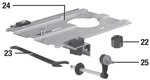
Product Familiarisation
- Turret Stops
- Chuck
- Shaft Lock Pin
- Depth Stop
- Depth Stop Lock Knob
- Plunge Selection Button
- Winder Handle
- Winder Handle Clutch Ring
- Brush Access Covers
- Micro Winder
- Motor
- Power Switch
- Retracting Power Switch Cover
- Plunge Spring Access Cap
- Speed Controller
- Plunge Lock Lever
- Safety Guards
- Dust Extraction Port
- Circle Cutting Pivot Mount
- Baseplate Mounting Knobs
- Fence
- Collet (see specification table for sizes)
- Spanner
- Extended Baseplate
- Table Height Winder
- Table Height Winder Connection Point
Intended Use
Hand-held, mains-powered plunge router used for cutting profiles, grooves, edges and elongated holes in natural and composite wood, and also stationary installation in the Triton Precision Router Table, the Triton Workcentre, and other suitable table systems.
Unpacking Your Tool
- Carefully unpack and inspect your new plunge router. Familiarise yourself with all its features and functions
- Ensure that all parts of the tool are present and in good condition
- If any parts are missing or damaged, have such parts replaced before attempting to use this tool
Before Use

WARNING: Ensure the tool is disconnected from the power supply before attaching or using any accessories, or making any adjustments.
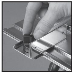
Collet and cutter installation
Note: Wear protective gloves when inserting and removing router bits due to the sharp edges of the cutters.
- Place the router upside down on a secure flat surface, with the motor completely stationary and the power cable removed from the mains
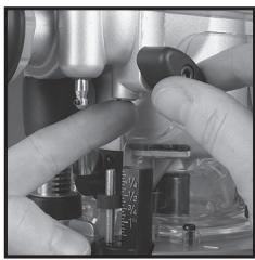
- Plunge the router to its maximum depth by pressing the Winder Handle Clutch Ring (8) inwards, and turning the Winder Handle (7) clockwise until the Collet (22) is protruding the base (image C)
Note: Ensure the Depth Stop (4) is fully retracted (see 'Depth stop and turret'). The Collet (22) should be protruding through the base, allowing easy spanner access.
-
Using the Spanner (23) provided, loosen the Collet by turning it anti-clockwise until removal (Image D)
-
Select the desired Collet, and install into the Chuck (2) by screwing the Collet in clockwise
- Insert the router cutter into the Collet ensuring that at least 20mm or half of the shaft (whichever is greater) is inserted into the Collet, then use the Spanner (23) to turn the Collet slightly, allowing the collet lock to engage. Once engaged, turn the spanner clockwise to tighten the cutter
- Return the router to a normal operating depth. This will disengage the collet lock and release the retracting switch shutter, enabling access to the Power Switch (12)
Dust extraction port
Note: The Triton Router is equipped with a Dust Extraction Port (18) for chip extraction above the cut. The Dust Extraction Port accepts 38mm (1%) outer-diameter hose. It is also compatible with the Triton Dust Collector (DCA300) and the Triton Dust Port Adaptor (TDPADIN) which allows for third-party hoses to be attached.
- The dust extraction hose screws into position via a left-hand thread (anti-clockwise)
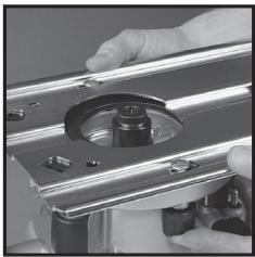
Extended baseplate and fence installation
Note: When using the router with the baseplate fitted, place one hand on the long end of the base, holding it down onto your work, and grip the router handle, furthest away, with your other hand.
- Locate the two Baseplate Mounting Knobs (20) and loosen them entirely. This permits the mounting studs to engage the router securing holes on the Extended Baseplate (24).
- Turn both the plunge router and the Extended Baseplate upside down
- Press the Baseplate Mounting Knobs on the plunge router inwards, to expose the mounting studs
- Align the mounting studs with the router securing holes on the Extended Baseplate (24), and slide into the keyhole slots (image E).
Note: The extended baseplate orientation is dependent on where the support is required. For edge work, locate the Power Switch (12) on the short overhang side of the base
- Tighten the Baseplate Mounting Knobs on the plunge router firmly to secure the plunge router to the Extended Baseplate
- To fit the Fence (21) loosen the fence knobs, and slide the fence along the tracks on the Extended Baseplate (Image F). Lock at the required setting by tightening both fence knobs
Note: When routing trenches at distance from an edge, fit the fence to the long end of the baseplate.
Note: When performing edge work with a non-bearing guided cutter, fit the fence to the short end of the baseplate (Image G)
Note: If using a very large diameter cutter it may be necessary to fix wooden blocks to the fence faces via the screw holes, to ensure the cutter does not contact the fence.
Operation

WARNING: ALWAYS wear eye protection, adequate respiratory and hearing protection, I as suitable gloves, when working with this tool.
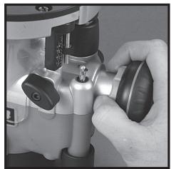
Switching on and off
Note: When the router is connected to the power source, the Power Switch (12) will illuminate in both 'On' and 'Off' positions.
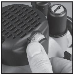
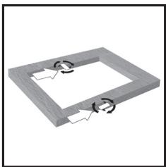
Note: The Retracting Power Switch Cover (13) prevents accidental starting of the router. It must be retracted before the router can be switched on (Image A). The cover will remain open until the router is switched off.
- Ensure that the plunge router is at the maximum extension of its travel, and that the cutter will not conflict with any foreign objects when it is powered on
- Connect the power cord to the mains, and slide the Retracting Power Switch Cover back to reveal the Power Switch
- Press the Power Switch in the 'I' position to turn the plunge router ON (Image B). Whilst the Power Switch is in this position, the Retracting Power Switch Cover will be prevented from re-covering the Power Switch
- To turn OFF, press the Power Switch in the 'O' position. The Retracting Power Switch Cover will slide back to its original position
Variable speed control
Note: Router speed settings are not critical. Generally the highest speed which does not result in burn marks on the workpiece should be used. Where stated, always follow the cutter manufacturers' maximum speed limitations.
- Operating at reduced speed increases the risk of damage to the router as a result of overload. Use very slow feed rates and/or multiple shallow cuts.
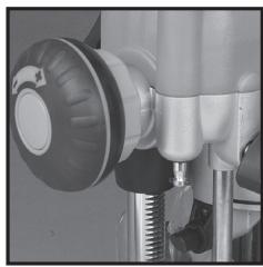
- The Speed Controller (15) is marked 1 to 5, corresponding approximately with the speeds and cutter diameters below. Turn the dial to select the required speed (image H)
| Setting | RPM | Cutter Diameter |
| 5 | 21,000 | Up to 25mm |
| 4 | 18,000 | 25 - 50mm |
| 3 | 14,500 | 50 - 65mm |
| 2 | 11,000 | Over 65mm |
| 1 | 8,000 | Use only if burning |
Cutting depth adjustment
Note: To lock the router at a particular depth of cut, plunge the router head down and rotate the Plunge Lock Lever (16) to its lower position. This will hold the router head in this position
- There are three methods of cut depth adjustment, depending on the accuracy and control required:
Free plunge
- Free plunge depth adjustments can be made with the Plunge Selection Button (6) engaged. Press the Plunge Selection Button deep inside the handle until it engages inward (image 1)
- Release the Plunge Lock Lever (16) and push the body of the router until the required depth is reached. Re-lock the Plunge Lock Lever
Note: The position of the Plunge Lock Lever can be altered by removing its retaining screw and repositioning the lever on the bolt. Re-tighten firmly.
Winder handle adjustment
- Plunge depth adjustments can be made by turning the Winder Handle (7)
- Disengage the Plunge Selection Button (6) and ensure that the button is flush with the Winder Handle (Image-J).
- To release the handle, pull the Winder Handle Clutch Ring (8) inwards
- Release the Plunge Lock Lever (16) and twist the Winder Handle until the desired depth of cut is reached. Release the Winder Handle Clutch Ring, and lock the Plunge Lock Lever
Micro Winder
Note: For use in Winder Handle (7) plunge mode only.
- Disengage the Plunge Selection Button (6), and ensure that the Plunge Lock Lever (16) is unlocked
Note: If the Micro Winder (10) is turned with the Plunge Lock Lever engaged, the Micro Winder will start clicking and the cut depth will remain unchanged. - Turn the Micro Winder clockwise to increase cut depth and anti-clockwise to reduce cut depth. Adjust the cut depth until the desired height is reached (Image K)
Note: When the end of the depth adjustment range is reached, the Micro Winder will offer greater resistance and will begin to 'click'.
- Engage the Plunge Lock Lever, particularly for heavy cuts
Depth stop and turret
- The Depth Stop (4) and Turret Stops (1) are used to accurately pre-set up to three different cut depths
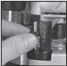
- Loosen the Depth Stop Lock Knob (5) and retract the Depth Stop (4) fully, then retighten (Image L)
- Set the turret posts to the required plunge depths using the scales on the stationary turret post (Image M)
Note: To change turret posts, rotate the entire turret assembly to align with the Depth Stop (Image N)
4. With the desired cutter installed into the Collet (22), adjust the plunge depth until the tip of the cutter touches the workpiece
5. Rotate the turret until the fixed turret post is in line with the Depth Stop. Release the stop, allowing it to spring onto the post, then retighten the Depth Stop Lock Knob. The plunge depth is now set at zero (Image 0)
6. Rotate the Turret Stops until the turret post with the desired plunge depth is aligned with the Depth Stop
Making a cut
Note: NEVER operate the router freehand without some form of guide. Guidance can be provided by a bearing guided router bit cutter, the supplied guides, or a straight edge (image P)
- ALWAYS hold the router using both hands, on the handles provided. Ensure that the workpiece will not move. Use clamps wherever possible
- Allow the motor to reach its full operating speed
- Lower the router bit cutter into the workpiece whilst moving the router slowly, keeping the base plate held flat against the workpiece
- If edge cutting, the cutting of the workpiece should be on the left side relative to the cutting direction (image Q). Keep the pressure constant and allow the cutter to work steadily through the material. Be aware that knots, and other variations, will slow the rate of progress
Note: To avoid 'bit chatter', direct the cut anti-clockwise for external cuts, and clockwise for internal cuts.
Note: Moving the router too fast can result in a poor quality finish, and overloading of the motor. Moving the router too slowly can result in overheating the workpiece.
Note: Normal operation of a router is to plunge the head after the router has been switched on.
Note:Do not operate the router upside down unless securely mounted in a well-guarded router table (eg. Triton brand).
Making multiple pass cuts
- The Turret Stops (1) allow the maximum depth of cut to be achieved in an operator-determined number of steps. Each step of the turret can be preset by adjusting the thumbwheel on the turret post
- Rotate the Turret Stops so that the Depth Stop will contact the highest pre-set turret post when the router is plugged. The first pass of the cut can now be made
- Continue to make passes, rotating the Turret Stops and adjusting the turret post depth for each pass when necessary until the full depth of cut has been achieved
Circle cutting
- Fit the Extended Baseplate (24), without the Fence (21) attachment, to the router
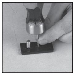
- Remove the Circle Cutting Pivot Mount (19) from the Extended Baseplate and fix it to the centre of the workpiece, using a small nail or screw, through one of the holes in the pivot mount (Image R). Leave the pivot mount bolt in position
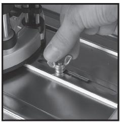
- Lower the router and base over the pivot mount and refit the washer and wing-nut (Image S)
- With the power switched 'Off', rotate the router along the intended path to check the circle, and make any necessary adjustments
- Cut the circle in several passes, lowering the cut depth by approximately 2mm (1/3^ ) each pass (Image T). Do not attempt to cut deeply in one pass
- Through cuts: if cutting all the way through the material, fix a sacrificial board to the underneath of the workpiece. Cut the circle oversize, then when the cut is all the way through, reduce the diameter and work back to the required size, using light, full depth passes
Table-mounted operation
WARNING: When in use with the Triton Workcentre Router Table Module WX7RT001, the maximum cutter diameter is 50mm ( 2% in^* ). This is constrained by the Workcentre specification.
Note: Fitting and operating this router on a router table should be carried out in accordance with the literature supplied with the router table.
Note: Whilst this product was designed for efficient and convenient operation on most router tables, it is particularly suited for use with the Triton Router Table RTA300.
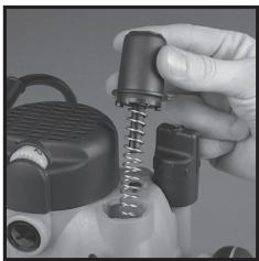
Note: The plunge spring MUST be removed before this router is fitted into a router table:
- Set the router at the top of its plunge range and engage the Plunge Lock Lever (16)
- Loosen the small screw next to the Plunge Spring Access Cap (14) a few turns.
- Holding the Plunge Spring Access Cap firmly so that the spring will not shoot upwards when released, twist the cap anti-clockwise to remove it (image U)
- Remove the spring and store in a safe place.
- Replace the Plunge Spring Access Cap and re-tighten the screw.
Note: Be sure to re-fit the plunge spring before using the router freehand.
The Table Height Winder (25) engages with the Table Height Winder Connection Point (26) for quick and easy above-the-table height adjustment when the router is table-mounted (image V)
Accessories
A wide range of suitable accessories for this tool are available from your Triton stockist, including a large selection of cutter/router bits. Spares including carbon brushes, guide bushes and collets are available from your Triton stockist or www.toolsparasonline.com
Maintenance
WARNING: ALWAYS disconnect from the power supply before carrying out any inspection, maintenance or cleaning.
General inspection
Regularly check that all the fixing screws are tight
- Inspect the supply cord of the tool, prior to each use, for damage or wear. Repairs should be carried out by an authorised Triton service centre. This advice also applies to extension cords used with this tool
Cleaning
WARNING: ALWAYS wear protective equipment including eye protection and gloves when cleaning this tool.
- Keep your tool clean at all times. Dirt and dust will cause internal parts to wear quickly, and shorten the device's service life
-
Clean the body of your machine with a soft brush, or dry cloth
-
Never use caustic agents to clean plastic parts. If dry cleaning is not sufficient, a mild detergent on a damp cloth is recommended
Water must never come into contact with the tool - Ensure the tool is thoroughly dry before using it.
- If available, use clean, dry, compressed air to blow through the ventilation holes (where applicable)
Lubrication
- Slightly lubricate all moving parts at regular intervals with a suitable spray lubricant
Brushes
Over time the carbon brushes inside the motor may become worn
- Excessively worn brushes may cause loss of power, intermittent failure, or visible sparking
- To replace the brushes, remove the two Brush Access Covers (9). Remove the worn brushes and ensure the sockets are clean. Carefully replace with new brushes and then replace the Brush Access Covers
- After fitting run the router without load for 2-3 minutes to help the brushes bed in. The process of the brushes fully bedding in may take repeated uses. Motor sparking may continue until new carbon brushes have bedded in
- Alternatively, have the machine serviced at an authorised service centre
Contact
For technical or repair service advice, please contact the helpline on (+44) 1935 382 222
Web: tritontools.com/en-GB/Support
Address:
Powerbox
Boundary Way
Lufton Trading Estate
Yeovil, Somerset
BA22 8HZ, United Kingdom
Storage
- Store this tool carefully in a secure, dry place out of the reach of children
Disposal
Always adhere to national regulations when disposing of power tools that are no longer functional and are not viable for repair.
- Do not dispose of power tools, or other waste electrical and electronic equipment (WEEE), with household waste
- Contact your local waste disposal authority for information on the correct way to dispose of power tools
Troubleshooting
| Problem | Possible cause | Solution |
| No function when Power Switch (12) is operated | No power | Check power supply |
| Defective On/Off Power Switch | Replace the Power Switch at an authorised Triton service centre | |
| Inaccurate cutting profile | Depth Stop (4) not correctly adjusted | Ensure that the Depth Stop corresponds to the maximum amount of cut permitted by the Turret Stops (1) |
| Incorrectly fitted or loose router bit/Collet (22) | Tighten router bit/Collet and cutter assembly | |
| Router will not operate | No supply of power | Check that power is available at source |
| Brushes worn or sticking | Disconnect power, open Brush Access Covers (9) and ensure brushes are not damaged or heavily worn | |
| Power Switch (12) is faulty | Have the tool serviced by an authorised Triton service centre | |
| Motor components faulty or short circuited | Have the tool serviced by an authorised Triton service centre | |
| Router runs or cuts slowly | Blunt or damaged cutter | Re-sharpen or replace cutter |
| Speed Controller (15) set low | Increase variable speed setting | |
| Motor is overloaded | Reduce pushing force on router | |
| Excessive vibration | Incorrectly fitted or loose router bit | Refit or tighten router bit |
| Bent or damaged router bit | Replace router bit | |
| Heavy sparking occurs inside motor housing | Brushes not moving freely | Disconnect power, remove brushes, clean or replace |
| Damaged or worn motor | Have the tool serviced by an authorised Triton service centre | |
| Micro Winder (10) “clicks” or not adjusting | Plunge Lock Lever (16) engaged | Release Plunge Lock Lever (16) |
| Reached end of adjustment range | Reset Micro Winder (10) and set depth with the Depth Stop (4) | |
| Makes an unusual sound | Mechanical obstruction | Have the tool serviced by an authorised Triton service centre |
| Damage to internal windings | Have the tool serviced by an authorised Triton service centre |
Guarantee
To register your guarantee visit our web site at www.tritontools.com* and enter your details.
Your details will be included on our mailing list (unless indicated otherwise) for information on future releases. Details provided will not be made available to any third party.
Purchase Record
Date of Purchase: //
Model: MOF001 Retain your receipt as proof of purchase
CE Declaration of Conformity
The undersigned: Mr Darrell Morris
as authorised by: Triton Tools
Declarethat: This declaration has been issued under the sole responsibility of the manufacturer. The object of the declaration is in conformity with the relevant Union harmonisation Legislation.
Identification code: MOF001
Description: Dual Mode Precision Plunge Router 1400W
Conforms to the following directives and standards:
Machinery Directive 2006/42/EC
EMC Directive 2014/30/EU
RoHS Directive 2011/65/EU
EN60745-1:2006+A11:2010
EN60745-2-17:2010
EN55014-1:2006+A1+A2
EN55014-2:2015
EN61000-3-2:2014
EN61000-3-3:2013
Triton Precision Power Tools guarantees to the purchaser of this product that if any part proves to be defective due to faulty materials or workmanship within 3 YEARS from the date of original purchase,
Triton will repair, or at its discretion replace, the faulty part free of charge.
This guarantee does not apply to commercial use nor does it extend to normal wear and tear or damage as a result of accident, abuse or misuse.
- Register online within 30 days.
Terms & conditions apply.
This does not affect your statutory rights
Notified body: TÜV SÜD Product Service
The technical documentation is kept by: Triton
Date: 30/08/2016
Signed:

Managing Director
Name and address of the manufacturer:
Powerbox International Limited, Company No. 06897059. Registered address: Powerbox,
Boundary Way, Lufton Trading Estate, Yeovil, Somerset, BA22 8HZ, United Kingdom.
Introductie
Offre soumise a conditions.
Signor Darrell Morris
NoOLLOWING:
NoOLLOWING:
No FOLLOWING:
No FOLLOWING:
No FOLLOWING:
Powerbox International Limited, Company No. 06897059. Registered address: Powerbox,
Boundary Way, Lufton Trading Estate, Yeovil, Somerset, BA22 8HZ, United Kingdom.
Wprowadzenie
Yeovil, Somerset, BA22 8HZ, United Kingdom.
BVeDHeHne
Blaogadarmi 3a bbl60 hInCTpyMeTrTlro. B 3om PykOBoCTBe CdoepjKHTcH INHpOAMn, He6bOxIMnIaB 63eONACHOH 3nEpdKTBHbN 3ckLNYaTaunu IN3dEMnIA. DAnHoe IN3dJIeN 0TNUaTcRA HEKOTOpBMYHNKALbHMM OOCHeHHMTMn, I JAAKe ECNs BnYb Yeke 3hAKoMbC 2a HANOTNbHMM IN3dJIeMN, BAXHO BHIMATEbNO pOHTaBt 3TO pyKOBoCTbO nNoHRTb CoDPkAuaNEcB H BmHcTHPcU. N6DfIEcB, TQKaKdby moNb3OBaTeB hINCTpyMeTA 03AHOKOMnC PcKOBoCTbO mNoHJ erO.
Смьовы Иобозаня.
Ha nacnoptnyko Tabinyu ky INHCTyMEnHa MOTyr 6bIb Ta HaeCEbHu CMMBOJI. Ohn npedctabrihot Baxhny Io KfOpMaNIO 6 O N3dEIN IIN INHCTpyKUIM no erO ekCNIyataaun.

IoiB30BaTbCpEcdTBaMn 3aunTbI opraHOB Cnyxa
Iolb30BaTbCpEcdTBaMn 3auNTbl OpraHOB 3peHnA
Iolb30BaTbCpeDCTBAMn 3aunTbI OprAHOB DbixAHN
Tolb3OBaTbc CpeDCTBAMn 3auNTbI rOIOBbI

Pb30BaTcRcpeCTBAMn 3aunTbypyK

IpoHTaTe pyKOBOCTBO

BEPEyb otdojna n Blanr!

BHMMHIE3 KcNpIyataunnpbopaDeTbmy, NmuIaM C or pArHnBbIMn
PhiHcKHeMN mY InuMCTBeHNbIMN BO3MOXHOCTmN mIaUM He
IMEIOUIMM DOCTaTOHORO ONbIa NIN 3HaHH, pa3peWaeTcR ToIbKO npN
ycIbONH,OTHOHNyDHTNAXOHTBcNAIO pNnCHMOTPMOTBEETBENHORO 3Aix6EZHONACbTHNINNJUAYOTo HrOeNOxDMJIbHE NHeTUPKYNIte npafoBe c nPiBOpOM.He octablanre TebeG3prNCMOTPAHnNE03aONJIyTe mNHPatc c nPiopOBom.
CoxpaHnTe Bce npedynpeJxdeHn I nHCTpyKuHa ha 6dyuiee.
Bpa3aene, nocebuHnHOM texhne 6eOnaCHoTH, TepMHN 一 E 那 k 是 P 州 H 中 P m H 103cTNCK K npOBOHbIM (paobatoJIOHMOT cETM), TAKH K eEcoNPOBHObIM (paobatoJIOHMOT AKKyMMITOPA) INCTPymEMT.
1) Be3onachoctb Ha pa6oem MeCTe
2) 3nektpo6e03onacHocTb
3)Личнaja6e3oNaChocTh
a) CnEduTe 3A cHToTOnO N cCbeBHeHcOeTHbO p6oHerO MeCTa. EecnIOpOK nI IHN HcDcTOtAK OCEBChEHI NOBIIaUOT BOPHTOBtHcHcEANTHOcNAYA.
6) He 6oBataTte C hEeKTOHnCTpyEMTON BO B3paBOIaONCHOTMOCIDEpe (HAnPMPE, B nPcNcYTBm BNOCLNAHEMIOXCA XHKIOKCTE, R3AOB INbIbIN). 3EeKTOHnCTpyEMHT BbPaBaTaIBaBET NCKpbl, KOTOpbBEOyT BOCANMAHNTb NbIb INNb Pnbl
B) BoPbMpa60tBu C 3NkEeKPOHCTPmEHTOM He No3OBaJIte TETMn NocToPOHHMMI pIbn6HKnBAtc Ka Bm. OOh bdyT OTbNeKaTb BaueBHMAnHe, Nbl MOKeTe NTpePTb yIptBaJIeHNBe.
a) BNIKN 3NEKTPOHNCTPYMHTA DOJIKHbI COOTBETCTBOBATbPO3ETKAM. KaTeROpHECKN 3ZnpeAEHTBcN BCHTbK CKAJIe-NeIO KEMENHEBA N KOCHTEPKUHYBNILOK. He PAPSEIAETCN DOKNJHOAT3A3EMENHbI 3NEKTPOHNCTPYMHTA K cTeT qHeP3 epeXoDHmN.PiIMENHEHc CTAndapTHbIX BNIOK COOTBETCTBOUHX IM PO3EK TO CHNKAeT P NCK NOPAJXHNN 3NEKTPINCEKHMMTOKOM.
6) HeKacaiTeBc3a3eMnEHbIX npEIMeT0r: TpyoNpOBoD0B, padiAtopoB, 1EeKTPuCHeCKNs pIITN H XOIOJIbHKnOB. EcIN Baue TE N3a3eMnEHO, TO nDCK nopAeHHner 3eKTPuCHeCKm TOKOM yBeYNHBAETC.
B) Ebergerite 3eKToPmHCTpyMENT OT Doxn H BnAaN. POnaJaIHe BOyD BYHTb 3eKToPmHCTpyMeHTa YbeYInuHaBt pNCK npaKeHHa 3eKToPmHcEKKM TOKOM.
r) He Donyckaite NopekdekHeNIA 3NEKTPnecKoTHI yHua.3a.napeaetcNEPepocHTb.TRHTbN.IIN OKTNIOuHTb3NEKTPNOHTpMHTNOT CETNa 3U npHyp.Eperitei UHPy oHarpeBa, KOtAKTa C mACnOM, OCTpBMn KPMOKAMNI BmDkyuMMeMeT aTeAaMM. NopEKeJdHnn NII 3aYTuTHbN IHyp YBvHnVHaET PNC NOPAJekEHNIA 3NEKTPnecKEM TOKOM.
ПИ Пав��с с дзкгпорнчсутим.TНВ ВОЕМСЕТДЛБУЗЛТС
ДУППЕТКЕРМ, РIMФОДьМД ДДЕСКПУЛТАЦМВ TAKHIXCYNBWAI.
ПИМЕЧЕНИДУПЛТЕР, РIMФОДatorioДДДЕСКПУЛТАЦМВ ВОЕМСЕТДЛ
СИKHJAET PICK NOPAKEXHIN 3DSKIPHTHECKN TOMOK.
eCtNnpa60ta BOBnAkhNxIcYCNbOHXNHe36KbHnA,To 3NeKtPOMHCTyPMHTE CnEETyNDoKNoTHK B KTOCTHNNHKY NITAHNA, CHa6XeHNHYOY cTPOJCTOBM 3aauTHIOr OTKnOHeYNH (Y30). PImmeHEHNI Y3O CHNXaTb PHCK nopXeAHN.3eKtPNrCEHM TKOM.
aBbTe BHNMaTeBnH, cIeNtte 3a Tm, TcO daen e PyKOBoDCTyBTEC 3ZapabMb CmblCNOM pRabocE 3JKeTPOINHCTpyMeHON. 3aPpeaTaCR NIOBbOaTBcR 3JKeTPOHNCTpyMeHON, ECLN BbYctANH NAnHOaDHTecb NOd DeiChBEM ANIKORON, HApKOTKNb INe KNEAPCTBeHNbX npneapATOs. IaXe kPbOKBpEMHNOe OcNaBnHE BHMNAH BO BPEM paBOToY PReBaTO TReJEL TPABM
6)non3y3tecbcpeCTBaAMnHbNDyAunbHOaauTb. Bcerda non3y3tecbcpeCTBaAMnAa3uTbOprAhoB 3epHHa.TpAmTOHe npmEHeHne cpeCTB 3auTb (hApmep, pecmpatopora, hckoNb3aueJe 3auTbOHoOBvI,KACKNI HcpeCTB 3auTbOprAhoB CNYa) CHNKaET DPK TPABM.
B) He Nyodcayrne HnepHdAmpeHORHO KIOHNOHU. NPeT eem KNTMAM NOKIINOAHb NTCPMTMEK P KOtEeW M/INK AKKYMUTPOy, NOHMMAT INI INepeHOCHITb ERO YbEIDNTECb, TTO BbIKIOuATEb IITAHNIA HAXOHTCB NBOJENOHXn BkIbKOHOHc. ECNI DEpKbT bAIENa CEbIKIOHOTe IITAHNA PPNI NEbEPHOCKSe IHNCTPMYETa HIN 3ApRkAtb IHNCTPymeT C BKNIOHcHbIM BkIbIOHOTeEM IITAHNIA TO PIck HecCACTHO GNYAUR YEBNVTCB.
3JIeKpIaTepeyINIOPOBOHbIe KIOHnIpeXeDEYEMBKOIOHbT 3JIeKpIHOHNCTPymET. TaeHHN KIOH, npICoEOJInEHNNK B BPAaIOUeCRA CTAH3JEKTOPHONCTPymETA, MOKET HnHECTI TpABM.
d) He TAnHTeBc 3a nppeIbKOMΦoPTHO30HbJDCoRFAeMOCTn. TBePOD CTOnIE Ha Horax H CoXpAHrTaPB aheBoHoeC. 3To nO3BcONHT yBepenHee KOHTOPINHOBaTb HtCPyMeHT BHexOxNAdHHbCITyUaYHae.
e) OdeaBaitteh NahtkExaHmM 6b03Am. CboDbadher Odejka H yKpaAehner He npocLyKaHTc. DepeXtBeBOncI, oDejxHy n HepatKn NoaJIbUeO To DVBxUYxHxCCTAHyNtHcyPMAHn. CboDbayHO eOJxDy, yKpaAehner Hn HnnHbHeBONCi MoKET hAMOTa H daBVxUYxueCnACTH.
K6) O63aTeIbNO bNo3yIeBcYpOToBCTaAMn BbTfAKn6cOpaB pIbn, eSCHONKOTPYkunnepeDyPcMOTPeBHe cOeHNHKeITAEJnHnKo6NJaOae npBaNa INx 3KcNpIyatauN. Taikke YcTOpOCTBa CHNKAOHt PnCKn, C8Ba3HHBe C npblBo
4) 3KcIpyataaJn 3JeKtpoHnCTpymeHa n yxoHm
A) hOnyckaie nepepyzHK 3eKPNOHCTPmeyHt. PpaBnIbHO NO6DnPaHte HNCTPYMHT eON CBA 3dQay. IaPOMTOoNO6pOchBHO
HrTcPymyB 6b7p8a0bTaKaeCTBeHHe8 He63oONACHe 63 nePBbIshnE HOMNHahbHOHarpyKu.
6) He paobataitc 3 nektpknohctpymtOM, cncb NkblnOHTbNPTAHNA HE BkLIIOAeTcH INHe BkLIIOAeTcH. IIOboJ 3nEkpTOHCTpymET C hepaB0aIIM bKbIIOAeTcH bONACn e NIOJeXHTMPOHTY.
B) OToCoaHnIe3NtEKnOPHTCMPTMOT OTPO3KTH N/IMNkAkyMylrToppa, PnKDEQcYEM BbIPOINRbT HbPcOyK, MeHbT OCHACTKY INI YKNLAbdbatBo rHO xPAHHeHE. IANHAR MaBpIpeDooTOPO:XHOCTN KHCNOuABET CnyAaHInh PyCK HcTPTMgHTA.
XaHnTHe 3NKeTOHPTOHrCYPMTBmEHTAe, HNOCTyINbHxIaR JI R
TeJeH, Hne NO3BOJIrte PABOTaTc C HMI NIIaJIam, HE 3HAKOBMlC M
3NKeTOHPTOHrCYPMTOM HIn He 3YNUBVHIM DaHbHe IN HCTPYKlMn.
3NKeTOHPTOHrCYPMT MoACEH B YEHbMeByPkAYx.
D) 6c3nKyBnAte3NtKePHTCHPTMEn. CnIeTne 3a TEm, Tc0b6 He bIoo B6HnHn HnIa3aHdAnen DBKyuXuXcR TaCteH, COnMAHNbHx Detanen IINn PnIH3NaKOB DpyHXN HeCNIPABNOCTei, CnOCoBHybN IOBNIATb HA pO8Oy TKeTPOHNCTPMMEnE. ECTN HtCPTMENP NOBEXHn, ToKcnLpYataaHIO pa3euaTaE TOB3ObHOBJIrTOJbKO nocpe MToPA. PtIHHIO MHONHv Hc+CeTHbIX CUYaeB CTAOBMTCR HEYDOBNTBOIPTeHLHO6cN2XHBHHe 3NeKTOPHOHCTPMMEnA.
e) CnEQTae 3A hTOTOn EPEXUPOE HNCTPymHTE uCOTONHEMERO pEXUYXK XPOMK. EcnE PEXUYK INHCTPYMHT NAdHeJcXuMbIg OpB303 o6ClyjxH, To CHNkXaBcTc BEOPTHOCTb 3auMeHNbINu O6JIeHrAETc YUPANBENHe.
K) Co6nJaaiae 3tni HNCTpymni pia 3eknIyatauni 3eKtPOHnCTpyMeHTA, OcHAcTKu n PEXkyUero HNCTpyMeHTA. YUHTbAiye TcNOBAAIO6eBHeO npDeTOnuea paObToI. IcNoJIbO3BaHne 3eKtPOHnCTpyMeHTA He No HA3HaYEnHO MOKet 6bItb ONaChbIM.
BHMMHIE! PnKcNpUyataaun HNCTPMeHa T a TepprntOpn ABCTpAinnn NIN HOBJ 3eAaJnHN peKOMENETCEBFA BKNIOHTa B cIeTNTANHYCytPOBTOA 3auATHO TOKIOHENH (Y3O) C HMOHNAHbHM OCTAOHbIM TKOTOM 30 mA INM ENHbUE.
5) PemoHT
a) PEmHT 3NkFTPOHCTPUMHTA DQnKHePNIOB3D0BtTcB KBAINHdNlRIOBAPOHBM CnIeNIAHOTC M CnONLbO3AHmE INDEHTHbXb HNACTeH. TOKbB A 30M CnIyAE PEmHT 3NkFTPOHCTPUMHTA HE CKAKETHR A HrO B630ANHOCHOTNPIuTeTbMbHOB6p3OM.
3HaKOMCTBO C N3dJIeHnEM
CoOTBcTByeT CJeDyUoIIM DnpeKTHBaM nCTaHdApTaM:
-Директугma Maшинham 2006/42/EC
-ДиpeKtBaNo 3JekTpOMaHHTHOI
COBMECTUMOCTN 2014/30/EC
- DnpeKtNbA 06 orpaHmUeHHN mCNoB3OBaHHN
BpeHbIX BeueCTB 2011/65/EU
EN60745-1:2006+A11:2010
EN60745-2-17:2010
EN55014-1:2006+A1+A2
EN55014-2:2015
EN61000-3-2:2014
EN61000-3-3:2013
YnolHMOeHHbI opraH: TUV SUD Product Service
Bnaedeneu texnuecko DokymeHTaun: Triton
Data: 30/08/2016
Poiinncs:

Tocnoin Dappel Moppc (Darrell Morris)
DinpekTop
Ha3BaHne n aDpec npOn3BODnTeIa:
Powerbox International Limited, Company No. 06897059. IOpndueckn
adpec: Powerbox, Boundary Way, Lufton Trading Estate, Yeovil, Somerset
BA22 8HZ, United Kingdom (BěmikópbárTaHnR).
Bevezetés
Registered address: Powerbox, Boundary Way, Lufton Trading Estate, Yeovil,
Somerset, BA22 8HZ, United Kingdom.
Uvod
Yeovil, Somerset, BA22 8HZ, United Kingdom.
Uvod
Dakujeme za zakupenie vyrobuk Triton. tento manuali obshajuie informacie nutne k bepezcnemu pouzivaniu a spravnemu fungovani toto vyrobku. Tento vyrobk panou nmaho jelinechny funkcil. Je mayne, ze ste u s podobynym vyrokom pracovali, naprikou temu si vskr precitaje tento manuali, aby ste naplino pochopili vsetky instrukcje. Uistite sa, ze kaźdy, kto s vyrokom pracujie, si tento manuali precitai o porozmulm je.
Použité symboly
Yeovil, Somerset, BA22 8HZ, United Kingdom.
Giris
Tanimlama kudu: MOF001
Açıkama: Ikili Mod Hassas Daldirmali Freze 1400W