CTB6250B - Fridge Freezer BEKO - Free user manual and instructions
Find the device manual for free CTB6250B BEKO in PDF.
User questions about CTB6250B BEKO
0 question about this device. Answer the ones you know or ask your own.
Ask a new question about this device
Download the instructions for your Fridge Freezer in PDF format for free! Find your manual CTB6250B - BEKO and take your electronic device back in hand. On this page are published all the documents necessary for the use of your device. CTB6250B by BEKO.
USER MANUAL CTB6250B BEKO
natural_image
Illustration of a kitchen range hood with three buttons (no text or symbols)CTB 6250 W
CTB 6250 B
CTB 6250 X
CTB 6250 XH
CTB 9250 X
CTB 9250 XH
EN
PT
RO
DE
DA
RU
FR
PL
SL
IT
LT
CS
ES
EL
SK
NL
BG
Please read this user manual first!
Dear Customer,
Thank you for preferring a Beko product. We hope that you get the best results from your product which has been manufactured with high quality and state-of-the-art technology. Therefore, please read this entire user manual and all other accompanying documents carefully before using the product and keep it as a reference for future use. If you handover the product to someone else, give the user manual as well. Follow all warnings and information in the user manual.
Remember that this user manual is also applicable for several other models. Differences between models will be identified in the manual.
Explanation of symbols
Throughout this user manual the following symbols are used:

Important information or useful hints about usage.

Warning for hazardous situations with regard to life and property.

Warning for electric shock.

Packaging materials of the product are manufactured from recyclable materials in accordance with our National Environment Regulations.
Do not dispose of the packaging materials together with the domestic or other wastes. Take them to the packaging material collection points designated by the local authorities.

This product was manufactured using the latest technology in environmentally friendly conditions.
| ENGLISH | 04-12 |
| DEUTSCH | 13-22 |
| FRANÇAIS | 23-32 |
| ITALIANO | 33-42 |
| ESPAÑOL | 43-52 |
| NEDERLANDS | 53-62 |
| PORTUGUÊS | 63-72 |
| DANSK | 73-82 |
| POLSKI | 83-92 |
| LIETUVIŲ K | 93-102 |
| ΕΛΛΗΝΙΚΑ | 103-115 |
| ΒЪЛГАРСКИ | 116-125 |
| ROMÂNĂ | 126-135 |
| PYССКИЙ | 136-147 |
| SLOVENŠČINA | 148-157 |
| ČESKY | 158-166 |
| SLOVENSKÝ | 167-176 |
01M-8842113200-4017-01
01M-8842103200-4017-01
01M-8844773200-4017-01
01M-8842043200-4017-01
01M-8844763200-4017-01
1
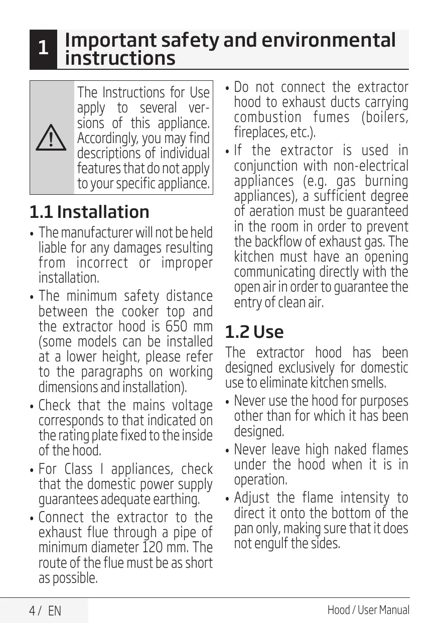
Important safety and environmental instructions

The Instructions for Use apply to several versions of this appliance. Accordingly, you may find descriptions of individual features that do not apply to your specific appliance.
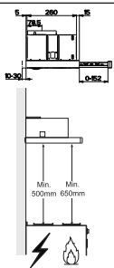
1.1 Installation
- The manufacturer will not be held liable for any damages resulting from incorrect or improper installation.
- The minimum safety distance between the cooker top and the extractor hood is 650 mm (some models can be installed at a lower height, please refer to the paragraphs on working dimensions and installation).
- Check that the mains voltage corresponds to that indicated on the rating plate fixed to the inside of the hood.
- For Class I appliances, check that the domestic power supply guarantees adequate earthing.
-
Connect the extractor to the exhaust flue through a pipe of minimum diameter 120 mm. The route of the flue must be as short as possible.
-
Do not connect the extractor hood to exhaust ducts carrying combustion fumes (boilers, fireplaces, etc.).
- If the extractor is used in conjunction with non-electrical appliances (e.g. gas burning appliances), a sufficient degree of aeration must be guaranteed in the room in order to prevent the backflow of exhaust gas. The kitchen must have an opening communicating directly with the open air in order to guarantee the entry of clean air.
1.2 Use
The extractor hood has been designed exclusively for domestic use to eliminate kitchen smells.
- Never use the hood for purposes other than for which it has been designed.
- Never leave high naked flames under the hood when it is in operation.
- Adjust the flame intensity to direct it onto the bottom of the pan only, making sure that it does not engulf the sides.
1
Important safety and environmental instructions
- Deep fat fryers must be continuously monitored during use; overheated oil can burst into flames.
- The hood should not be used by children or persons not instructed in its correct use.
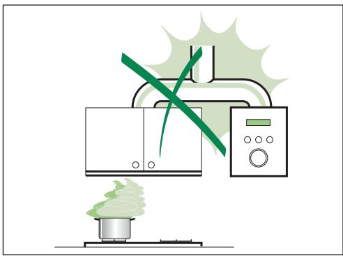
natural_image
Illustration of a microwave oven with a green X-shaped mark and a steaming pot on a base, emitting vapor (no text or symbols)1.3 Maintenance
- Switch off or unplug the appliance from the mains supply before carrying out any maintenance work.
- Clean and/or replace the Filters after the specified time period (Fire hazard).
- Clean the hood using a damp cloth and a neutral liquid detergent.
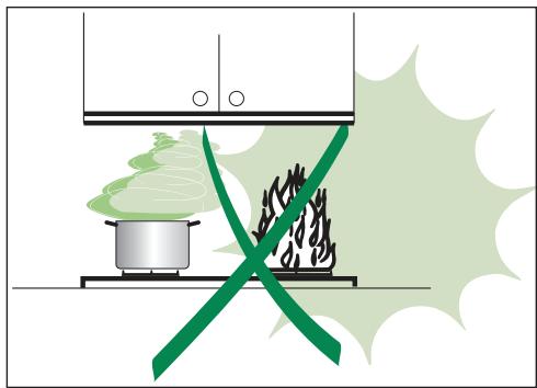
natural_image
Illustration of a cooking setup with a pot and steam rising, crossed by a green diagonal line (no text or symbols)1
Important safety and environmental instructions
1.4 Compliance with the WEEE Directive and Disposing of the Waste Product:
This product complies with EU WEEE Directive (2012/19/EU). This product bears a classification symbol for waste electrical and electronic equipment (WEEE).

This product has been manufactured with high quality parts and materials which can be reused and are suitable for recycling. Do not dispose of the waste product with normal domestic and other wastes at the end of its service life. Take it to the collection center for the recycling of electrical and electronic equipment. Please consult your local authorities to learn about these collection centers.
Compliance with RoHS Directive
The product you have purchased complies with EU RoHS Directive (2011/65/EU). It does not contain harmful and prohibited materials specified in the Directive.
1.5 Package information

Packaging materials of the product are manufactured from recyclable materials in accordance with our National Environment Regulations. Do not dispose of the packaging materials together with the domestic or other wastes. Take them to the packaging material collection points designated by the local authorities.
2
Characteristics
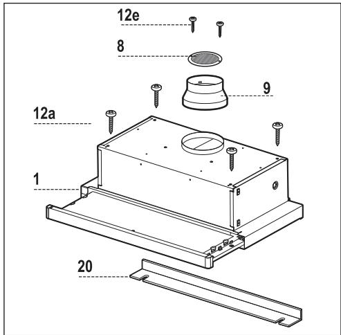
2.1 Components
Ref. Q.ty Product Components
| 1 | 1 | Hood Body, complete with:Controls, Light, Blower, Filters |
| 8 | 1 | Directional Air Outlet grille |
| 9 | 1 | Reducer Flange ø 150-120 mm |
| 20 | 1 | Closing element |
Ref. Q.ty Installation Components
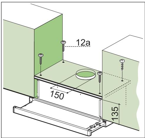
| 12a | 4 | Screws 4,2 x 44,4 |
| 12e | 2 | Screws 2,9 x 9,5 |
| Q.ty | Documentation | |
| 1 | Instruction Manual |
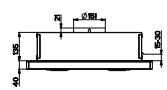
2.2 Dimensions
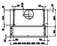
2.3 Technical Specifications
| CTB 6250 W | CTB 6250 B | CTB 6250 X/XH | CTB 9250 X/XH | |
| Width | 598 mm | 898 mm | ||
| Depth | 175 mm | |||
| Height | 280 mm | |||
| Supply voltage | 220 - 240 V, 50-60 Hz | |||
| Control | 3 positions | |||
| Suction power | 420 m^3/h | |||
| Motor power | 140 W | |||
| Lamp power | 2X28 W | |||
| Air outlet pipe diameter | 120-150 mm | |||
| Net weight | 7,6 kg | 9,3 kg | ||
| Gross weight | 8,5 kg | 10,5 kg | ||
| Color | White | Black | Inox | Inox |
Markings on the product or the values stated in other documents supplied with the product are values obtained under laboratory conditions as per relevant standards. These values may vary according to the usage of the product and ambient conditions.
3
Installation
3.1 Drilling the Support surface and Fitting the Hood
Screw Fitting
- The hood support surface must be 135 mm above the bottom surface of the wall units.
- Drill the support with a ø 4,5 mm drill bit, using the drilling template provided.
- Cut a hole ø 120-150 mm in size on the support surface, using the drilling template provided.
- Fix using the 4 screws 12a (4,2 x 44,4) provided.
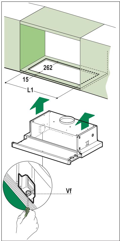
Snap-On Fitting
- The hood can be installed either directly on the bottom surface of the wall units using snap-on side supports.
- Cut a fitted opening in the bottom surface of the wall unit, as shown.
- Insert the hood until the side supports snap into place.
- Lock in position by tightening the screws Vf from underneath the hood.

| Hood Type | CTB 6250 W/B/X | CTB 9250 X |
| L1 | 510 | 810 |
3
Installation
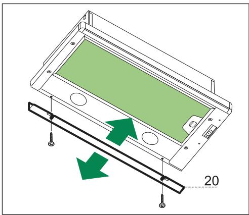
Closing Element
- The space between the edge of the hood and the rear wall can be closed by applying the element 20 provided, using the screws supplied for this purpose.
natural_image
Diagram of a device casing with green internal panel and directional arrows indicating movement, no text or symbols present.3.2 Connection
3.2.1 Ducted Version Air Exhaust System
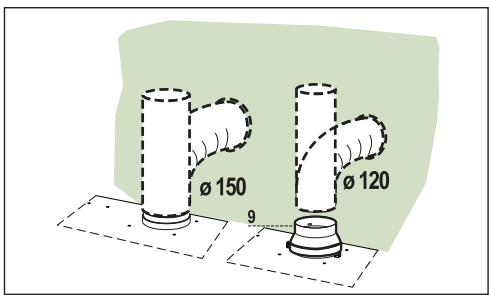
When installing the ducted version, connect the hood to the chimney using either a flexible or rigid pipe 150 or 120 mm, the choice of which is left to the installer.
- To install a ø 120 mm air exhaust connection, insert the reducer flange 9 on the hood body outlet.
- Fix the pipe in position using sufficient pipe clamps (not supplied).
- Remove possible charcoal filters.
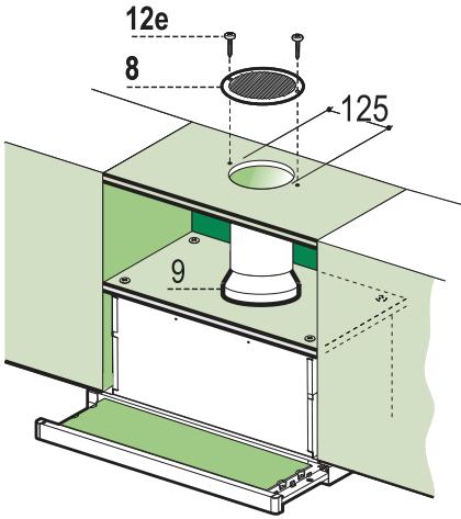
3.2.2 Recirculation Version Air Outlet
- Cut a hole 125 mm in any shelf that may be positioned over the hood.
- Insert the reducer flange 9 on the hood body outlet.
- Connect the flange to the outlet on the shelf over the hood by using a flexible or rigid pipe ø120 mm.
- Fix the pipe in position using sufficient pipe clamps (not supplied).
- Fix the air outlet grid 8 on the recirculation air outlet by using the 2 screws 12e (2,9 x 9,5) provided.
- Ensure that the activated charcoal filters have been inserted.
3.2.3 Electrical Connection
- Connect the hood to the mains through a two-pole switch having a contact gap of at least 3mm.
- When opening the sliding carriage for the first time after installing the hood, pull it out briskly until it clicks.
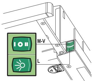
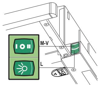
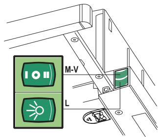
4 Use
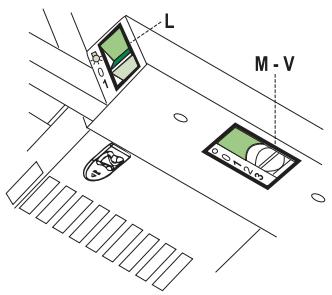

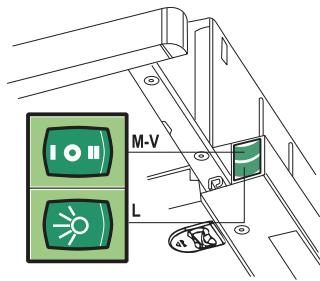
4.1 Control panel
| L | Light | Switches the lighting system on and off |
| M | Motor | Switches the extractor motor on and off |
| V | Speed | Sets the operating speed of the extractor:1. Low speed, used for a continuous and silent air change in the presence of light cooking vapour.2. Medium speed, suitable for most operating conditions given the optimum treated air flow/noise level ratio.3. Maximum speed, used for eliminating the highest cooking vapour emission, including long periods |
| L | Light | Switches the lighting system on and off |
| M | Motor | Switches the extractor motor on and off |
| V | Speed | Sets the operating speed of the extractor:1. Low speed, used for a continuous and silent air change in the presence of light cooking vapour.2. Medium speed, suitable for most operating conditions given the optimum treated air flow/noise level ratio. |
5
Maintenance
5.1 Grease Filters
5.1.1 Cleaning Metal Self-Supporting Grease Filters
- The filters must be cleaned every 2 months, or more frequently in case of particularly heavy use of the hood. Filters can be washed in a dishwasher.
- Pull out the sliding suction panel.
- Remove the filters one by one, after having disconnected the relative fastening elements.
- Wash the filters, taking care not to bend them. Let them get dry before refitting them. (The colour of the filter surface may change throughout the time but this has no influence to the filter efficiency).
- When refitting the filters, make sure that the handle is visible on the outside.
- Close the sliding suction panel.
natural_image
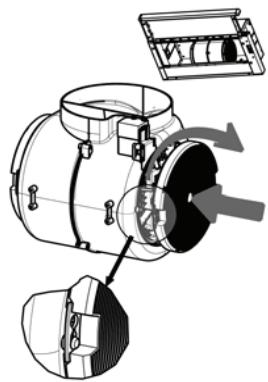
Illustration of a hand pressing a green directional arrow on a green circular background (no text or symbols)5.2 Charcoal filter (Recycling version)
5.2.1 Replacing Charcoal Filters

Warning: Turn the lights off and wait until the lamps cool down before you change the odour filter.
- These filters are not washable and cannot be regenerated, and must be replaced approximately every four months or more frequently by particularly heavy use.
- Pull out the sliding suction panel.
- Remove the grease filters.
- Remove the saturated carbon filter by releasing the fixing hooks
- Fit the new filter by hooking it into its seating.
- Replace the grease filters.
- Close the sliding suction panel.
natural_image
Technical diagram of a mechanical device with internal components and directional arrows indicating motion (no text or symbols)5.3 Lighting
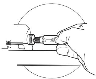
5.3.1 Light Replacement
28W light
- Remove the metal grease filters.
- Unscrew the bulbs and replace them with new ones having the same characteristics.
- Replace the metal grease filters.
natural_image
Line drawing of a hand using a tool to adjust or install a mechanical component (no text or symbols present)natural_image
Illustration of a microwave oven with a green X-shaped exhaust cone and a gas stove emitting smoke (no text or symbols)1
natural_image
Illustration of a cooking setup with a pot and stirrer, crossed by a green smoke cover (no text or symbols)natural_image
Diagram of a device casing with green internal panel and directional arrows indicating movement, no text or symbols present.3.2.1 Anschlüss in abluftversion
natural_image
Illustration of a hand pressing a green directional arrow on a road sign (no text or symbols present)natural_image
Technical line drawing of a mechanical device with internal components and directional arrows (no text or symbols)5.3 Beleuchtung
5.3.1 AUSWECHSELN DER LAMPEN
Lampen 28W
natural_image
Line drawing of a hand using a tool to adjust or install a mechanical component (no text or symbols present)natural_image
Illustration of a microwave oven with a green X-shaped exhaust cone and a steaming pot on a base (no text or symbols)1
natural_image
Illustration of a cooking setup with a pot and steam rising, crossed by a green diagonal line (no text or symbols)natural_image
Technical diagram of a device casing with green internal panel and directional arrows indicating movement, no text or symbols present.3.2 Branchements
3.2.1 Sortie air version aspirante
natural_image
Illustration of a hand pressing a green directional arrow on a road sign (no text or symbols present)5.2 Filtres anti-odeur (Version Recyclage)
5.2.1 REMPLACEMENT

natural_image
Technical diagram of a mechanical device with internal components and directional arrows (no text or labels)5.3 Eclairage
5.3.1 Remplacement Lampes Lampes de 28W
natural_image
Line drawing of a hand using a tool to adjust or install a mechanical component (no text or symbols present)natural_image
Illustration of a microwave oven with a green smoke rising from a pot on a stove, emitting vapor or steam (no text or symbols)1
natural_image
Illustration of a cooking setup with a pot and steam rising, crossed by a green diagonal line (no text or symbols)- The hood can be installed either directly on the bottom surface of the wall units using snap-on side supports.
- Cut a fitted opening in the bottom surface of the wall unit, as shown.
- Insert the hood until the side supports snap into place.
- Lock in position by tightening the screws Vf from underneath the hood.
| Tipo Cappa | CTB 6250 W/B/X | CTB 9250 X |
| L1 | 510 | 810 |
Profilo Di Chiusura
natural_image
Technical diagram of a device casing with green internal components and directional arrows indicating movement or assembly (no text or symbols)3.2 Connessioni
4.1 Quadro comandi
natural_image
Illustration of a hand pressing a green directional arrow on a road sign (no text or symbols present)5.2 Filtri antiodore (Versione Filtrante)
5.2.1 Sostituzione

natural_image
Technical diagram of a mechanical device with internal components and directional arrows (no text or labels)5.3 Illuminazione
natural_image
Line drawing of a hand holding a tool with a screw, enclosed in a circular frame (no text or symbols)natural_image
Illustration of a microwave oven with a green X-shaped exhaust plume and a steaming pot on a base (no text or symbols)1.3 Mantenimiento
natural_image
Illustration of a cooking setup with a pot and steam rising, crossed by a green diagonal line (no text or symbols)1
natural_image
Diagram of a device casing with green internal panel and directional arrows indicating assembly or movement (no text or symbols)3.2 Conexión
4.1 Panel de control
natural_image
Illustration of a hand pressing a green directional arrow on a road sign (no text or symbols present)natural_image
Technical diagram of a mechanical device with internal components and directional arrows (no text or labels)5.3 Iluminación
natural_image
Line drawing of a hand using a tool to adjust or install a mechanical component (no text or symbols present)natural_image
Illustration of a microwave oven with a green X-shaped mark and a steaming base, emitting vapor (no text or symbols)1
natural_image
Illustration of a heating setup with a pot and smokestack, crossed by a green diagonal line (no text or symbols)natural_image
Diagram of a device casing with green internal panel and directional arrows indicating movement, no text or symbols present.3.2 Aansluitingen
natural_image
Illustration of a hand pressing a green directional arrow on a green circular background (no text or symbols)5.2 Geurfilter (Filterversie)
5.2.1 Vervanging

natural_image
Technical diagram of a mechanical device with internal components and directional arrows (no text or labels)5.3 Verlichting
natural_image
Line drawing of a hand holding a mechanical component, no text or symbols presentnatural_image
Illustration of a kitchen appliance with a green diagonal line crossing over it, emitting smoke from a pot (no text or symbols)1
natural_image
Illustration of a cooking setup with a pot and steam rising, crossed by a green diagonal line (no text or symbols)natural_image
Diagram of a device casing with green internal panel and directional arrows indicating assembly or movement (no text or symbols)3.2 Ligações
4.1 Quadro de comandos
natural_image
Illustration of a hand pressing a green directional arrow on a road sign (no text or symbols present)natural_image
Technical diagram of a mechanical device with internal components and directional arrows indicating motion (no text or symbols)5.3 Iluminação
natural_image
Line drawing of a hand using a tool to adjust or install a mechanical component (no text or symbols present)natural_image
Illustration of a kitchen appliance with a green crossed-out blade and a steaming pot, emitting smoke (no text or symbols)1
natural_image
Illustration of a cooking setup with a pot and steam rising, crossed by a green diagonal line (no text or symbols)natural_image
Diagram of a device casing with green internal panel and two green arrows indicating movement, labeled '20' (no text or symbols on the diagram itself)3.2 Tilslutninger
natural_image
Illustration of a hand pressing a green directional arrow on a green circular background (no text or symbols)5.2 Lugabsorberende filtre (Recirkulation gennem filter)
5.2.1 Udskiftning

natural_image
Technical diagram of a mechanical device with internal components and directional arrows (no text or labels)5.3 Lys
natural_image
Line drawing of a hand using a tool to adjust or install a mechanical component (no text or symbols present)natural_image
Illustration of a microwave oven with a green double-headed crossed lid and a steaming pot on a base (no text or symbols)1.3 Konserwacja
natural_image
Illustration of a cooking setup with a pot and two steamers, crossed by a green diagonal line (no text or symbols)1
natural_image
Diagram of a device casing with green internal panel and directional arrows indicating movement, no text or symbols present.3.2 Przyłączenie
natural_image
Illustration of a hand pressing a green directional arrow on a road sign (no text or symbols present)natural_image
Technical illustration of a mechanical device with internal components and a close-up view of a component (no text or symbols)5.3 Oświetlenie
natural_image
Line drawing of a hand using a tool to adjust or install a mechanical component (no text or symbols present)natural_image
Illustration of a kitchen appliance with a green X-shaped mark and a steaming pot nearby (no text or symbols)natural_image
Illustration of a cooking setup with a pot and firecracker, crossed by a green diagonal line (no text or symbols)1
natural_image
Diagram of a device casing with green internal panel and two green arrows indicating movement, labeled '20' (no text or symbols on the diagram itself)3.2 Prijungimas
4.1 Valdymo skydelis
natural_image
Illustration of a hand pressing a green directional arrow on a green circular background (no text or symbols)5.2 Anglinis filtras (vienkartinio naudojimo)
natural_image
Technical diagram of a mechanical device with internal components and directional arrows (no text or labels)5.3 Apšvietimas
natural_image
Line drawing of a hand holding a tool, no text or symbols presentnatural_image
Illustration of a microwave oven with a green double-bonding pan emitting steam, next to a control panel (no text or symbols)1
natural_image
Illustration of a cooking setup with a pot and fire, crossed by a green diagonal line (no text or symbols)natural_image
Technical diagram of a device with green internal components and directional arrows indicating movement or assembly (no text or symbols)3.2 Σύνδεση
4.1 Πίνακας ελέγχου
natural_image
Illustration of a hand pointing at a green circular road sign with a directional arrow (no text or symbols)natural_image
Technical diagram of a mechanical device with internal components and directional arrows indicating flow or movement (no text or symbols present)5 Συντήρηση
5.3 Φωτισμός
natural_image
Line drawing of a hand holding a tool with a screw, no text or symbols presentnatural_image
Illustration of a kitchen with a steaming pot and a green X-shaped crossed-out device (no text or symbols)1
natural_image
Illustration of a cooking setup with a pot and two steamers, crossed by a green diagonal line (no text or symbols)natural_image
Technical diagram of a device casing with green internal panel and directional arrows indicating assembly (no text or symbols)3.2 Свързване
natural_image
Illustration of a hand pressing a green directional arrow on a road sign (no text or symbols present)natural_image
Technical diagram of a mechanical device with internal components and directional arrows (no text or labels)5.3 Осветление
natural_image
Line drawing of a hand using a tool to adjust or install a mechanical component (no text or symbols present)natural_image
Illustration of a kitchen appliance with a steaming pot and a green X-shaped mark, emitting vapor or smoke (no text or symbols)1.3 Întreținere
natural_image
Illustration of a cooking setup with a pot and smoke being heated by a horizontal stove, crossed out by a green diagonal line (no text or symbols)1
natural_image
Diagram of a device casing with green internal panel and two green arrows indicating movement, labeled '20' (no text or symbols beyond basic diagram)3.2 Racordare
3.2.3 Racord electric
natural_image
Illustration of a hand pressing a green directional arrow on a green circular background (no text or symbols)natural_image
Technical illustration of a mechanical device with internal components and a close-up view of a component (no text or symbols)5.3 Iluminare
natural_image
Line drawing of a hand using a tool to adjust or install a mechanical component (no text or symbols present)natural_image
Illustration of a kitchen setup with a steaming pot and a crossed-out refrigerator (no text or symbols)1
natural_image
Illustration of a cooking setup with a pot and steam rising, crossed by a green diagonal line (no text or symbols)1
natural_image
Diagram of a device casing with green internal components and directional arrows indicating movement or force (no text or symbols)3.2 Подключение
natural_image
Illustration of a hand pressing a directional arrow on a green circular road surface (no text or symbols)natural_image
Technical line drawing of a mechanical device with internal components and directional arrows (no text or symbols)natural_image
Line drawing of a hand holding a small mechanical component, no text or symbols presentPred uporabo naprave preberite navodila za uporabo!
Spoštovani kupci!
natural_image
Illustration of a kitchen appliance with a green X-shaped mark and a steaming pot, emitting smoke (no text or symbols)1.3 Vzdrževanje
natural_image
Illustration of a cooking setup with a pot and two steamers, crossed by a green diagonal line (no text or symbols)| Ref. | Količina | Deli izdelka |
| 1 | 1 | Hood Body, complete with: Controls, Light, Blower, Filters |
| 8 | 1 | Directional Air Outlet grille |
| 9 | 1 | Reducer Flange ø 150-120 mm |
| 20 | 1 | Closing element |
natural_image
Diagram of a device with green internal components and directional arrows, no text or symbols present3.2 Povezava
3.2.1 Napa z odvodom zraka
natural_image
Illustration of a hand pressing a green circular road sign with a green arrow symbol (no text or numbers present)5.2 Oglen filter (možnost recikliranja)
natural_image
Technical diagram of a mechanical device with internal components and directional arrows (no text or labels)5 Vzdrževanje
5.3 Osvetlitev
5.3.1 Menjava luči 28 W luč
natural_image
Line drawing of a hand holding a mechanical component, no text or symbols presentnatural_image
Illustration of a microwave oven with a green X-shaped exhaust plume and a steaming pot nearby (no text or symbols)1.3 Údržba
natural_image
Illustration of a cooking setup with a pot and two steamers, crossed by a green diagonal line (no text or symbols)natural_image
Technical diagram of a device casing with green internal panel and directional arrows indicating movement, no text or symbols present.3.2 Připojení
natural_image
Illustration of a hand pressing a green directional arrow on a green circular background (no text or symbols)natural_image
Technical diagram of a mechanical device with internal components and directional arrows (no text or labels)5.3 Osvětlení
natural_image
Line drawing of a hand using a tool to adjust a mechanical component (no text or symbols present)natural_image
Illustration of a microwave oven with a green crossed-out kitchen pan and a steaming pot nearby (no text or symbols)
natural_image
Illustration of a cooking setup with a pot and steam rising, crossed by a green diagonal line (no text or symbols)1
natural_image
Technical diagram of a device casing with green internal panel and directional arrows indicating movement, no text or symbols present.3.2 Pripojenie
4.1 Ovládací panel
natural_image
Illustration of a hand pressing a green directional arrow on a road sign (no text or symbols present)natural_image
Technical diagram of a mechanical device with internal components and directional arrows indicating motion (no text or symbols)5.3 Osvetlenie
natural_image
Line drawing of a hand using a tool to adjust a mechanical component (no text or symbols present)