
HL 850 EB - Belt sander FESTOOL - Free user manual and instructions
Find the device manual for free HL 850 EB FESTOOL in PDF.
| Product type | Belt sander (planer) |
| Brand | FESTOOL |
| Model | HL 850 EB |
| Power | 850 W |
| No-load speed | 11000 rpm |
| Planing width | 82 mm |
| Adjustable depth of cut | 0 - 3.5 mm |
| Rebate depth | Unlimited |
| Weight (without cable) | 3.9 kg |
| Protection class | II (double insulation) |
| Power supply | Mains (cable) |
| Sound pressure level | 80 dB(A) |
| Sound power level | 91 dB(A) |
| Vibration emission value | < 2.5 m/s² |
| Electronic functions | Soft start, constant speed, electronic brake |
| Chip ejection | Right or left (reversible) |
| Tool holder | HK 82 SD with helical cutter |
| Rebate depth stop | 0 - 30 mm (accessory) |
| Parallel guide | 0 - 82 mm (accessory) |
| Angular stop | Yes (accessory) |
| Stationary use | With SE-HL device (accessory) |
| Rustic tool holders | HK 82 RG, HK 82 RF, HK 82 RW (accessories) |
| Maintenance | Clean cooling openings, keep blades sharp |
| Warranty | 24 months (EU), 12 months minimum elsewhere |
Frequently Asked Questions - HL 850 EB FESTOOL
User questions about HL 850 EB FESTOOL
0 question about this device. Answer the ones you know or ask your own.
Ask a new question about this device
Download the instructions for your Belt sander in PDF format for free! Find your manual HL 850 EB - FESTOOL and take your electronic device back in hand. On this page are published all the documents necessary for the use of your device. HL 850 EB by FESTOOL.
USER MANUAL HL 850 EB FESTOOL
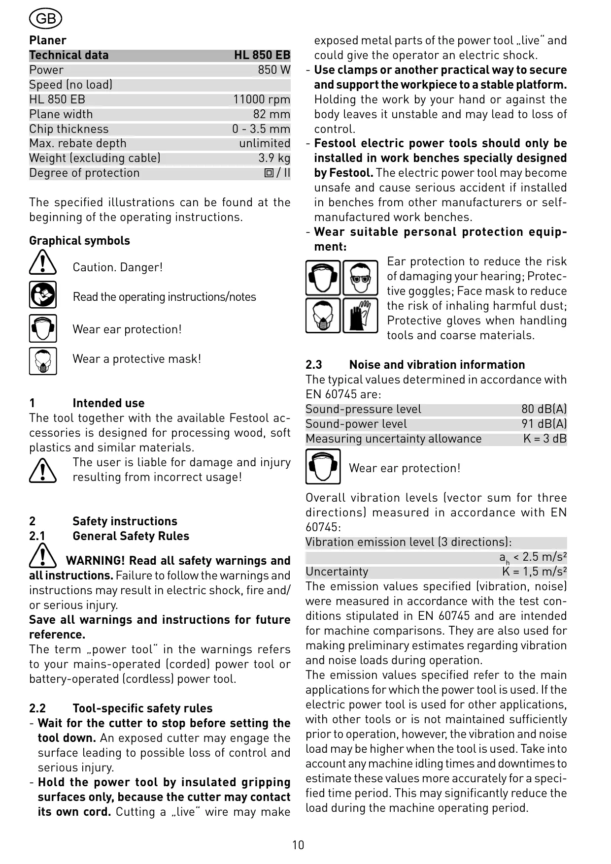
| Technical data | HL 850 EB |
| Power | 850 W |
| Speed (no load) | |
| HL 850 EB | 11000 rpm |
| Plane width | 82 mm |
| Chip thickness | 0 - 3.5 mm |
| Max. rebate depth | unlimited |
| Weight (excluding cable) | 3.9 kg |
| Degree of protection | ☐/ ☐ |
The specified illustrations can be found at the beginning of the operating instructions.
Graphical symbols

Caution. Danger!

Read the operating instructions/notes

Wear ear protection!

Wear a protective mask!
1 Intended use
The tool together with the available Festool accessories is designed for processing wood, soft plastics and similar materials.

The user is liable for damage and injury resulting from incorrect usage!
2 Safety instructions
2.1 General Safety Rules

WARNING! Read all safety warnings and
all instructions. Failure to follow the warnings and instructions may result in electric shock, fire and/ or serious injury.
Save all warnings and instructions for future reference.
The term „power tool" in the warnings refers to your mains-operated (corded) power tool or battery-operated (cordless) power tool.
2.2 Tool-specific safety rules
- Wait for the cutter to stop before setting the tool down. An exposed cutter may engage the surface leading to possible loss of control and serious injury.
- Hold the power tool by insulated gripping surfaces only, because the cutter may contact its own cord. Cutting a „live“ wire may make
exposed metal parts of the power tool „live“ and could give the operator an electric shock.
- Wear suitable personal protection equipment:
- Use clamps or another practical way to secure and support the workpiece to a stable platform. Holding the work by your hand or against the body leaves it unstable and may lead to loss of control.
- Festool electric power tools should only be installed in work benches specially designed by Festool. The electric power tool may become unsafe and cause serious accident if installed in benches from other manufacturers or self-manufactured work benches.

Ear protection to reduce the risk of damaging your hearing; Protective goggles; Face mask to reduce the risk of inhaling harmful dust; Protective gloves when handling tools and coarse materials.
2.3 Noise and vibration information
The typical values determined in accordance with EN 60745 are:
$$ \text {S o u n d - p r e s s u r e l e v e l} \quad 8 0 \mathrm {d B (A)} $$
$$ \text {S o u n d - p o w e r l e v e l} \quad 9 1 \mathrm {d B (A)} $$
$$ \text {M e a s u r i n g} \quad K = 3 \mathrm {d B} $$

Wear ear protection!
Overall vibration levels (vector sum for three directions) measured in accordance with EN 60745:
Vibration emission level (3 directions):
$$ a _ {h} < 2. 5 m / s ^ {2} $$
$$ \text {U n c e r t a i n t y} \quad K = 1, 5 \mathrm {m} / \mathrm {s} ^ {2} $$
The emission values specified (vibration, noise) were measured in accordance with the test conditions stipulated in EN 60745 and are intended for machine comparisons. They are also used for making preliminary estimates regarding vibration and noise loads during operation.
The emission values specified refer to the main applications for which the power tool is used. If the electric power tool is used for other applications, with other tools or is not maintained sufficiently prior to operation, however, the vibration and noise load may be higher when the tool is used. Take into account any machine idling times and downtimes to estimate these values more accurately for a specified time period. This may significantly reduce the load during the machine operating period.
3 Power supply and start-up

The mains voltage must correspond to the specification on the rating plate.
To switch on, first press the switch lock (1.1) and then the switch (1.2) (press = ON, release = OFF).
4 Electronics

The tool has full-wave electronics with the following features:
Smooth start-up
The smooth start-up ensures the router starts up jolt-free.
Constant speed
The pre-selected speed remains constant whether the machine is in operation or in neutral position.
Brake (HL 850 EB)
After switching-off, the tool is electronically brought to a standstill in 1.5 - 2 seconds.
5 Machine settings

Always remove the power supply plug from the socket before carrying out any work on the machine.
5.1 Chip thickness adjustment
- Open the lock (3.1) by pressing to the rear.
- Set the chip thickness by turning the handle (3.2). The scale (3.3) indicates the set chip thickness.
- Close the lock (3.1) by pressing to the front to lock the set chip thickness.
The max. planing depth is 3.5 ~mm . So as no to overload the machine, we recommend that a maximum planing depth of 2.5 ~mm be set with a plane width >40 ~mm .
By turning the handle beyond the 0 ~mm marking, you reach position P = Park position. In position P , the planer head cutter is pulled back completely behind the planer platen. Important: This does not apply to the rustic planer heads.
5.2 Planing head, planer blade

Use only cutters which are sharp and undamaged. Blunt cutters increase the danger of kick-back and reduce the planning quality obtained.
The planer is equipped with planer head HK 82 SD
as standard series. The planer head has inclined, fitted cutters, which is why the cutters cannot be reground.
Changing the planer head
- Press and hold in the spindle lock (1.6).
- Use the hexagon wrench (2.7) to open the screw (2.2).
- Pull the planer head [2.6] from the shaft.
- Clean the shaft of any deposits that may be present.
- Mount a new planer head on the shaft.
- Secure the new planer head with the clamping flange (2.4), shim (2.3) and screw (2.2). Tighten the screw (2.2) firmly.
Changing the cutters
- Use the hexagon wrench (1.4) to release the three screws (4.1) in the planer head.
- Pull the spiral cutter (4.2) out of the planer head at the side.
- Clean the support groove for the cutter. Important: To prevent corrosion on the planer head, the pH-value of the cleaning agent used must be between 4.5 and 8.
- Push a new spiral cutter (4.2) with the labelled side aligned to the rear planer platen into the support groove of the planer head.
- Use a guide rail (4.3) to align the cutter so that the front side is flush with the front and rear platen of the planer.
- First tighten the middle screw, then the two outer screws (4.1).
5.3 Fitting the guides
(partly accessories)
Rebating depth guide FA-HL
The rebating depth guide (2.1) is mounted in the threaded hole (2.14) on the front right of the machine.
The stop can be infinitely adjusted to between 0 and 30 ~mm in accordance with the scale. The rebating depth which has been set can be read against the notch (2.13).
Parallel guide PA-HL
The parallel guide (2.11) is fitted in the threaded hole (2.9) on the left side of the tool.
When planing along an edge a planing width of between 0 and 82 ~mm can be set with the stop after loosening the catch (2.10).
Angle stop WA-HL
The angle stop is secured in the tapped bore (2.9) in the same way as the parallel stop.
5.4

Dust extraction
Always connect the machine to a dust extractor.
Chip removal is actuated via the rocker lever (5.2) either through the right (5.3) or left (5.4) opening. A chip collection bag or extraction hose (dia. 36 mm) can be connected at both openings.
Chip collecting bag SB-HL (accessories)
The chip collecting bag is secured via adapter AD-HL (5.6). The adapter is attached by flap (5.5) to the lower edge of the chip removal opening and screwed in by means of rotary button (5.7) in the tapped bore (5.1).
Extraction hose
An extraction hose (dia. 36 ~mm ) can either be fitted directly in the chip removal opening, or in the adapter AD-HL for the chip collecting bag.
6 Putting the planer down
When working with electric planers you must remember that the planer shaft continues to run for a few seconds after the tool is switched off. The HL 850 EB has a support foot (2.8) at the end of the platen so that it can be placed safely on a work surface. If the electric tool is taken up, the support foot automatically protrudes beyond the planer platen to ensure that the planer shaft is always raised above flat work surfaces when the planer is put down.

Pay attention to the following when putting the HL 850 EB down:
- check that the support foot is present and fully operational,
- wait until the planer shaft comes to a standstill before putting the tool down.
If the support foot should be found obstructive during special planing work it can be swung back out of the way and locked in position (2.8).
7


Working with the machine
The surface to be planed must be free of metallic objects.
Always secure the workpiece in such a manner that it cannot move while being sawed.

The machine must always be held with both hands by the designated handles [1.3, 1.7].
Procedure
- First set The desired chip thickness.
- Place The front platen onto The workpiece but do not allow The planer head to come into contact with The wood.
- Switch on the planer.
- Guide The planer over The workpiece so that The platen rests flat on The workpiece. Press on The front planer platen when starting to plane and on The rear planer platen (end of workpiece) when continuing or finishing planing.
7.1 Rebating
The planer can rebate to an unlimited depth.
To do this, fold away the protective cover (2.5) by first pushing the lever (1.5) forward and then laterally to the left. The front of the planer head is now exposed.
When work is completed, the protective cover moves back automatically to initial position through spring force.
7.2 Chamfering
The front planer platen is equipped with a 90^ V groove (2.12) to allow the chamfering of workpiece edges. This V groove is 2mm deep, thus producing a 2mm edge chamfer with the chip thickness setting 0.
7.3 Bench-mounted operation
The planer can be operated bench-mounted in conjunction with the bench-mounting device SE-HL. Detailed instructions are supplied with the accessories.
7.4 Rustic planer heads (accessories)
The planer can also be used to create rustic surfaces. Three rustic planer heads are available for this purpose:
- HK82RG: creates a surface with a coarse structure.
- HK 82 RG: creates a surface with a fine structure.
- HK 82 RW: creates an uneven, wavy surface.
The blades on the rustic planing head (HK 82 RF, HK 82 RG, HK 82 RW) protrude approx. 1.5 ~mm over the planer foot.
When using rustic planing heads on the planer, set the cutting depth to 0 ~mm . Otherwise there is
a risk that the blades on the head will cut into the planer foot and destroy the planer.
The cutting depth limiter (6.2) prevents the cutting depth from increasing inadvertently while planing work is performed.
Always attach the cutting depth limiter to the planer before working with a rustic planing head:
- Set the cutting depth on the planer to 0 mm ,
- Attach the cutting depth limiter by inserting the rotary knob (6.1) through the limiter and into the threaded hole (6.3).
8 Accessories, tools

For your own safety, use only original Festool accessories and spare parts.
The accessory and tool order number can be found in the Festool catalogue or on the Internet under "www.festool.com".
9 Maintenance and care

Always remove the power supply plug from the socket before carrying out any work on the machine.

All maintenance and repair work which requires the motor casing to be opened may only be carried out by an authorised service centre.
The cool air openings in the motor casing must always be kept clean and unobstructed to ensure air circulation.
The tool is fitted with special motor brushes with an automatic cut-out. When the brushes become worn the power supply is shut off automatically and the tool comes to a standstill.
10 Disposal
Do not throw the power tool in your household waste! Dispose of the machine, accessories and packaging at an environmentally-responsible recycling centre! Observe the valid national regulations.
EU only: European Directive 2002/96/EC stipulate that used electric power tools must be collected separately and disposed of at an environmentally responsible recycling centre.
11 Warranty
Our equipment is under warranty for at least 12 months with regard to material or production faults in accordance with national legislation. In the EU countries, the warranty period is 24 months (an invoice or delivery note is required as proof of purchase). Damage resulting from, in particular, normal wear and tear, overloading, improper handling, or caused by the user or other damage caused by not following the operating instructions, or any fault acknowledged at the time of purchase, is not covered by the warranty. Damage caused by the use of non-original accessories and consumable material (e.g. sanding pads) is also excluded.
Complaints will only be acknowledged if the equipment has not been dismantled before being sent back to the suppliers or to an authorised Festool customer support workshop. Store the operating instructions, safety notes, spare parts list and proof of purchase in a safe place. In addition, the manufacturer's current warranty conditions apply.
Note
We reserve the right to make changes to the technical data contained in this information as a result of ongoing research and development work.
REACH for Festool products, their accessories and consumables
REACH is a European Chemical Directive that came into effect in 2007. As "downstream users" and product manufacturers, we are aware of our duty to provide our customers with information. We have set up the following website to keep you updated with all the latest news and provide you with information on all the materials used in our existing products: www.festool.com/reach
Rabot
5.2 Porte-outsils, couteau

8 Accessoires, outfits

5.4 OTCacbIBaHne NblJN

Bcerda nodklouaTe MaunHy K BbITJKe.
Bb6poc ctpyKmoKeT npOn3BoNDtbcq uepe3 npaboe (5.3) nIu chepe3 leBoe (5.4) oTBepcTne. IpeekIoueHne ocUeCTBnEETcC nOMOUsbpyKn (5.2). K o6oM OTBePCTnM MoXHo NODCoEINHTb MeWOK dJa c6opactpyKnnI IN BCaCbIBaIOuNn ShlaHr ( 36MM)
Mewokдясбopaстружkn SB-HL (ochacTk)
MewoK dIy c6opa cTpyxkN KpeHNTcI c NOMOu bIO aAnTepa AD-HL (5.6).Aaantep 3auePJIeTcR JaBbUcKOM (5.5) 3a HnXHIOU KpOMky OTBepCTnI dJIa Bbl6pOca cTpyxkN c NOMoU bINHTa-6apawka (5.7) npBvHHuBaETcR K pe3b6OBomy OTBepCTnI (5.1).
BcacbibaouniuHaHr
BcacsbIbaUoenn 36 MM) moXHo nOdknO- uHTb KaK HeNocepDCTBeHNO K OTBepCTNIO dJa Bbl- 6poca cTpyxKn, TaK N KaAanTepy AD-HL dJa MeuKa dJa c6opac TpyxKn.
6 yctaHOBka py6aHka
Pn pa6oTe c 3JleKtpopy6aHkamn CJIeDyeT yuects, TTO BaI py6aHka nOcIe BbIKluOeHnI np60pa eU, HeCKoNsKO ceKynI BpauaetcI NO INHePcNl.
UTo6bl npn60p 6bl yctaHOBlen Ha, XHo, HL 850 EB Ha KOHcpe NODOWbI py6aHka cHa6K, H onopHoi HOxKOi (2.8). Pn npnOdHMaHm 3JIeKTPOnp60pa ONOPHaj HOXKa ABTomatNueCKn BbICTyNaET 3a NODOWBy py6aHka HAcTOLSko, UTo6bl npn YCTaHOBKe py6aHka Ha pOBHyIO NOBepraHOCTs ero BaJI BceTdA OCTaBaJcra CBO6OHNbIM.

При установке HL 850 EB Heoobdmo yuects cneyuouee:
- Y6eIntecs B TOM, yTO OnOpHa HoxKa npedCTaBJIeHa n ΦyHKUOHNpyeT 6e3ynpeuHo,
Bcerda ykpenlaTe o6pa6aTbIbAemyo DeTaJIb TaK, UTo6bI OHa He DnBraIacb npu o6pa6oTke.

Bcerda depxknte maunHy dBym pykaMn 3a npedna3NaueHHbIeIy eTOrOpyuKn(1.3,1.7).
Popraok deiCTBn
- YcTaHOBNTs Tpe6yEmyTOJIuHNy CTpyKKn.
- YctaHOBNTs py6aHOK npeDnei NOoSWBOH Ha 3aTOTOBKY, He KacayCS npn 3TOM 3aTOTOBKN CTporansHO rOJOBKOJ.
- BkIouHTs py6aHok.
- Bectn py6aHOK no 3aROTOBKe TAKIM o6pa30m, yTo6bI erO nOoUBa JexKaJaHa 3aROTOBKe PLOCKO. PpN 3TOM B Haayane CtpOraHnHa rpyKAts IpeEHNIO nOoUbBy py6aHka, a B cepeDInHe N KOHcE erO - 3aDNIO.
7.1 BbI6OpKaYeTBeptN
C pomoubpo ybaHka moxho npo3B0ntb Bbl60pyeTbeTpHeoRpaHnueHHo rIybuHbl.
Iocne oKoHuaHna pa60TbI 3aUHTbI KOxUx NOd DeiCTBnEM npyXnHbI ABToMaTuYeCKN BCTaHeT Ha CBOe MeCTO.
7.2 ChTne fackn
PpHaIeXHocTn, HNCTpyMeHTbI

Дя сбстVENHо 6e3oNaChocTN nC- noь3yIte TOLbKO opuRnHaJIbHbIe npiCnoc6blenN I 3aIacHbIe qactN φnpMbI Festool.
Homepa 3aka3a Дя пинадлжно Teи nHCTpyMeHTOB BbI NaITe B KaTalore Festool nIn B INHTepHET no aDpecy „www.festool.com".

06cnykBaHne uyoxd

Ipeed nauaIom IIO6oB pa60tbcMaunHO Bcerda BbHmamte WTeNceIb n3 po3eTKn! BCEpa60tbo no 6cnykubAHNO npemOnTy, KOToPbIe Tpe6yeT OTKpbIBaHNA KOpnyca DBNrataJIa, MOryT pOn3BOIDITbcra ToJbKO aBTOpu3OBAHHo MaCTepCKo CepBnCHo cLyX6bl.
Для obecneueHЯ zuKyIaIu B03duXa OTBepCTna Для oxJaXeHЯ B KOpnyce DBrIaTeJI BcerIa ДоJxHbI 6blTb OTKpbITbIMn UcHcTBIMn.