
CSC SYS 50 EB-Basic - Table saw FESTOOL - Free user manual and instructions
Find the device manual for free CSC SYS 50 EB-Basic FESTOOL in PDF.
| Product type | Cordless portable table saw |
| Brand | Festool |
| Model | CSC SYS 50 EB-Basic |
| Transport dimensions (L x W x H) | 512 x 396 x 296 mm |
| Table height | 228 mm |
| Weight (without batteries) | 20.2 kg |
| Power supply | 36 V DC (two Festool BP 18 battery packs ≥ 4 Ah) |
| No-load speed | 6,800 rpm |
| Speed adjustment | 6 levels |
| Blade diameter | 168 mm |
| Blade bore | 20 mm |
| Blade thickness | 1.2 mm |
| Cutting width | 1.8 mm |
| Cutting height at 0° | 0 - 48 mm |
| Cutting height at 45° | 0 - 34 mm |
| Rip capacity at 90° | 450 mm |
| Rip capacity at 45° | 340 mm |
| Maximum parallel cutting width | 280 mm |
| Blade tilt angle | -10° to 47° |
| Miter angle (sliding table) | 0 - 70° |
| Display and control | Screen with buttons, rotary selector, switch and STOP button |
| Electronic functions | Motorized height and angle adjustment, calibration, favorite memories (4 + storage position) |
| Safety | Protective cover, blade guard, push stick, STOP button |
| Maintenance | Cleaning of sliding table guides and limit stops |
| Included accessories | Parallel rip fence, snap-in miter fence, table extension, Allen key, blade guard for invisible cuts, dust bag |
Frequently Asked Questions - CSC SYS 50 EB-Basic FESTOOL
User questions about CSC SYS 50 EB-Basic FESTOOL
0 question about this device. Answer the ones you know or ask your own.
Ask a new question about this device
Download the instructions for your Table saw in PDF format for free! Find your manual CSC SYS 50 EB-Basic - FESTOOL and take your electronic device back in hand. On this page are published all the documents necessary for the use of your device. CSC SYS 50 EB-Basic by FESTOOL.
USER MANUAL CSC SYS 50 EB-Basic FESTOOL
Markus Stark
Head of Product Development

Denis Drobner
Head of Product Conformity
We as the manufacturer declare under our sole responsibility that the product(s) fulfill(s) all the relevant provisions of the following UK Regulations and are manufactured in accordance with the following designated standards:
S.I. 2008/1597 Supply of Machinery [Safety] Regulations 2008
S.I. 2016/1091 Electromagnetic Compatibility Regulations 2016
S.I. 2017/1206 Radio Equipment Regulations 2017
S.I. 2021/422 Restriction of the Use of Certain Hazardous Substances in Electrical and Electronic Equipment Regulations 2012
BS EN 62841-1:2015
BS EN 62841-3-1:2014 + A11:2017
BS EN 55014-1:2017 + A11:2020, BS EN 55014-2:2015
BS EN 55032:2015 + A11:2020
EN 300 328 V2.2.2
EN303446-1V1.2.1
EN 301 489-1 V2.2.3, EN 301 489-17 V3.2.4
BS EN IEC 63000:2018
UK Approved Body for UK Type-examination:
Technology International (Europe) Ltd.
Unit 56, Shrivenham Hundred Business Park
Shrivenham, Swindon. SN6 STY
United Kingdom
Approved Body Number: 0673
UK Type-examination Certificate Number: TI(E) / SOMSR(08) - UKTE / 94 / 09122022

Signed on behalf of and in name of
Festool GmbH
Wertstr. 20, 73240 Wendlingen, GERMANY
Place and date of declaration: Wendlingen, 2022-12-09

Markus Stark
Head of Product Development

Denis Drobnner
Head of Product Conformity
Inhaltsverzeichnis
1 Symbols 26
2 Safety warnings. 26
3 Intended use. 30
4 Technical data. 31
5 Parts of the device. 31
6 Control module. 31
7 Commissioning. 32
8 Battery pack. 32
9 Settings 33
10 Working with the electric power tool.....36
11 Transportation 38
12 Service and maintenance. 38
13 Accessories. 40
14 Environment. 40
15 General information. 40
16 Troubleshooting 40
1 Symbols

Warning of general danger

Warning of electric shock

Risk of pinching fingers and hands!

Read the operating instructions and safety instructions.

Wear ear protection.

Wear a dust mask.

Wear protective gloves when changing tools!

Wear protective goggles.

Do not dispose of it with domestic waste.

Tool contains a chip which stores data. See section 15.2

CE marking: Confirms the conformity of the power tool with the European Community directives.

UKCA marking: The United Kingdom Conformity Assessed symbol is a marking for products being placed on the market in the United Kingdom. It is a manufacturers indication that the product is in conformance with the relevant regulations in the UK.

Tip or advice

Handling instruction

Inserting the battery pack.

Remove the battery pack.

Direction of rotation of saw and the saw blade

- Parked position adjustment marking

Move the saw blade to the parked position with the control module to change the spacer wedge.
2 Safety warnings
2.1 General power tool safety warnings

WARNING! Read all safety warnings, instructions, illustrations and specifica
tions provided with this power tool. Failure to follow all instructions listed below may result in electric shock, fire and/or serious injury.
Save all warnings and instructions for future reference.
The term "power tool" in the warnings refers to your mains-operated (corded) power tool or battery-operated (cordless) power tool.
Follow the operating manual for the charger and the battery pack.
2.2 Safety warnings for bench-mounted circular saws
1) Guarding related warnings
-
Keep guards in place. Guards must be in working order and be properly mounted. A guard that is loose, damaged, or is not functioning correctly must be repaired or replaced.
-
Always use saw blade guard and riving knife for every through-cutting operation. For through-cutting operations where the saw blade cuts completely through the thickness of the workpiece, the guard and other safety devices help reduce the risk of injury.
- Immediately reattach the guarding system after completing an operation (such as rabbeting, dadoing or resawing cuts) which requires removal of the guard and riving knife. The guard and riving knife help to reduce the risk of injury.
- Make sure the saw blade is not contacting the guard, riving knife or the workpiece before the switch is turned on. Inadvertent contact of these items with the saw blade could cause a hazardous condition.
- Adjust the riving knife as described in this instruction manual. Incorrect spacing, positioning and alignment can make the riving knife ineffective in reducing the likelihood of kickback.
- For the riving knife and anti-kickback device to work, they must be engaged in the workpiece. The riving knife and anti-kickback device are ineffective when cutting workpieces that are too short to be engaged with the riving knife and anti-kickback device. Under these conditions a kickback cannot be prevented by the riving knife and anti-kickback device.
- Use the appropriate saw blade for the riving knife. For the riving knife to function properly, the saw blade diameter must match the appropriate riving knife and the body of the saw blade must be thinner than the thickness of the riving knife and the cutting width of the saw blade must be wider than the thickness of the riving knife.
2) Cutting procedures warnings
DANGER: Never place your fingers or hands in the vicinity or in line with the saw blade. A moment of inattention or a slip could direct your hand towards the saw blade and result in serious personal injury.
- Feed the workpiece into the saw blade only against the direction of rotation. Feeding the workpiece in the same direction that the saw blade is rotating above the table may result in the workpiece, and your hand, being pulled into the saw blade.
- Never use the litre gauge to feed the workpiece when ripping and do not use the rip fence as a length stop when cross cutting with the litre gauge. Guiding the workpiece with the rip fence and the litre gauge at the same time increases the likelihood of saw blade binding and kickback.
- When ripping, always apply the workpiece feeding force between the fence and the saw blade. Use a push stick when the distance between the fence and the saw blade is less than 150 ~mm , and use a push block when this distance is less than 50 mm. "Work helping" devices will keep your hand at a safe distance from the saw blade.
- Use only the push stick provided by the manufacturer or constructed in accordance with the instructions. This push stick provides sufficient distance of the hand from the saw blade.
- Never use a damaged or cut push stick. A damaged push stick may break causing your hand to slip into the saw blade.
- Do not perform any operation "freehand". Always use either the rip fence or the mi-tre gauge to position and guide the workpiece. "Freehand" means using your hands to support or guide the workpiece, in lieu of a rip fence or mi-tre gauge. Freehand saw-ing leads to misalignment, binding and kickback.
- Never reach around or over a rotating saw blade. Reaching for a workpiece may lead to accidental contact with the moving saw blade.
- Provide auxiliary workpiece support to the rear and/or sides of the saw table for long and/or wide workpieces to keep them level. A long and/or wide workpiece has a tendency to pivot on the table's edge, causing loss of control, saw blade binding and kickback.
- Feed workpiece at an even pace. Do not bend or twist the workpiece. If jamming occurs, turn the tool off immediately, disconnect the battery pack then clear the jam. Jamming the saw blade by the workpiece can cause kickback or stall the motor.
- Do not remove pieces of cut-off material while the saw is running. The material may become trapped between the fence or inside the saw blade guard and the saw blade pulling your fingers into the saw blade.
English
Turn the saw off and wait until the saw blade stops before removing material.
- Use an auxiliary fence in contact with the table top when ripping workpieces less than 2 ~mm thick. A thin workpiece may wedge under the rip fence and create a kickback.
3) Kickback causes and related warnings
Kickback is a sudden reaction of the workpiece due to a pinched, jammed saw blade or mis-aligned line of cut in the workpiece with respect to the saw blade or when a part of the workpiece binds between the saw blade and the rip fence or other fixed object.
Most frequently during kickback, the workpiece is lifted from the table by the rear portion of the saw blade and is propelled towards the operator.
Kickback is the result of saw misuse and/or incorrect operating procedures or conditions and can be avoided by taking proper precautions as given below.
- Never stand directly in line with the saw blade. Always position your body on the same side of the saw blade as the fence.
Kickback may propel the workpiece at high velocity towards anyone standing in front and in line with the saw blade. - Never reach over or in back of the saw blade to pull or to support the workpiece.
Accidental contact with the saw blade may occur or kickback may drag your fingers into the saw blade. - Never hold and press the workpiece that is being cut off against the rotating saw blade. Pressing the workpiece being cut off against the saw blade will create a binding condition and kickback.
- Align the fence to be parallel with the saw blade. A misaligned fence will pinch the workpiece against the saw blade and create kickback.
- Use a featherboard to guide the workpiece against the table and fence when making non-through cuts such as rabbeting, dodoing or resawing cuts. A featherboard helps to control the workpiece in the event of a kickback.
- Use extra caution when making a cut into blind areas of assembled workpieces. The protruding saw blade may cut objects that can cause kickback.
Support large panels to minimise the risk of saw blade pinching and kickback. Large panels tend to sag under their own weight. Support(s) must be placed under all portions of the panel overhanging the table top.
- Use extra caution when cutting a workpiece that is twisted, knotted, warped or does not have a straight edge to guide it with a litre gauge or along the fence. A warped, knotted, or twisted workpiece is unstable and causes misalignment of the kerf with the saw blade, binding and kickback.
- Never cut more than one workpiece, stacked vertically or horizontally. The saw blade could pick up one or more pieces and cause kickback.
- When restarting the saw with the saw blade in the workpiece, centre the saw blade in the kerf so that the saw teeth are not engaged in the material. If the saw blade binds, it may lift up the workpiece and cause kickback when the saw is restarted.
- Keep saw blades clean, sharp, and with sufficient set. Never use warped saw blades or saw blades with cracked or broken teeth. Sharp and properly set saw blades minimise binding, stalling and kickback.
4) Table saw operating procedure warnings
- Turn off the table saw and disconnect the battery pack when removing the table insert, changing the saw blade or making adjustments to the riving knife or saw blade guard, and when the machine is left unattended. Precautionary measures will avoid accidents.
- Never leave the table saw running unattended. Turn it off and don't leave the tool until it comes to a complete stop. An unattended running saw is an uncontrolled hazard.
- Locate the table saw in a well-lit and level area where you can maintain good footing and balance. It should be installed in an area that provides enough room to easily handle the size of your workpiece. Cramped, dark areas, and uneven slippery floors invite accidents.
- Frequently clean and remove sawdust from under the saw table and/or the dust
collection device. Accumulated sawdust is combustible and may self-ignite.
- The table saw must be secured. A table saw that is not properly secured may move or tip over.
- Remove tools, wood scraps, etc. from the table before the table saw is turned on. Distraction or a potential jam can be dangerous.
Always use saw blades with correct size and shape (diamond versus round) of arbour holes. Saw blades that do not match the mounting hardware of the saw will run off-centre, causing loss of control. - Never use damaged or incorrect saw blade mounting means such as flanges, saw blade washers, bolts or nuts. These mounting means were specially designed for your saw, for safe operation and optimum performance.
- Never stand on the table saw, do not use it as a stepping stool. Serious injury could occur if the tool is tipped or if the cutting tool is accidentally contacted.
- Make sure that the saw blade is installed to rotate in the proper direction. Do not use grinding wheels, wire brushes, or abrasive wheels on a table saw. Improper saw blade installation or use of accessories not recommended may cause serious injury.
2.3 Safety instructions for the pre-assembled saw blade
Usage
- The maximum speed specified on the saw blade must not be exceeded and the speed range must be adhered to.
- The pre-installed saw blade is only designed for use in circular saws.
- Proceed with extreme care when unpacking, packing and handling the tool (e.g. installing it in the machine). There is a risk of injury from extremely sharp cutting edges!
- When handling the tool, wearing safety gloves provides a more secure hold of the tool and further reduces the risk of injury.
- Circular saw blades with cracked bodies must be replaced. Repair is not permitted.
-
Circular saw blades with a combination design (soldered saw teeth) with saw tooth thickness smaller than 1mm must no longer be used.
-
WARNING! Do not use tools with visible cracks or blunt or damaged cutting edges.
Installation and mounting
- Tools must be clamped in such a way that they cannot come loose during operation.
- When assembling the tools, it must be ensured that the clamping takes place on the tool hub or the clamping surface of the tool, and that the cutting edges do not come into contact with other components.
- Do not lengthen the key or tighten by hitting with a hammer.
- The clamping surfaces must be cleaned to remove contamination, grease, oil and water.
- Clamping screws must be tightened according to the manufacturer's instructions.
- Only securely installed rings, e.g. rings that have been pressed in or those that are held in position by an adhesive bond, may be used to adjust the hole diameter of circular saw blades to the spindle diameter of the machine. The use of loose rings is not permitted.
Service and maintenance
- Repairs and sanding work may only be carried out by Festool customer service workshops or experts.
- The tool design must not be changed.
- Deresinify and clean the tool regularly (cleaning agent with pH between 4.5 and 8).
- Blunt edges can be resharpened on the clamping surface to a minimum cutting edge thickness of 1 ~mm .
- Only transport the tool in suitable packaging - risk of injury!
2.4 Further safety instructions

Wear suitable personal protective equipment: Ear protection, safety goggles, a dust mask for work that generates dust.
- Harmful/toxic dust may be produced during your work (e.g. paint containing lead, certain types of wood or metals). Contact with or inhalation of this dust may pose a risk for the operating personnel or persons in the vicinity. Comply with the safety regulations that apply in your country.
- Wear suitable breathing protection to protect your health. In enclosed spaces, en-
English
sure that there is sufficient ventilation and connect a mobile dust extractor.
- Check whether there are any signs of damage to the housing components, such as cracks or stress whitening. Have any damaged components repaired before using the power tool.
- Do not use power supply units or third-party battery packs to operate cordless power tools. Do not use third-party chargers to charge the battery packs. The use of accessories not expressly authorised by the manufacturer can result in electric shocks and/or serious accidents.
2.5 Sawing aluminium
When sawing aluminium, the following measures must be taken for safety reasons:

Wear protective goggles.
- Connect the power tool to a suitable dust extractor with an antistatic suction hose.
- Regularly clean dust deposits from the motor housing on the power tool.
Use an aluminium saw blade. - When sawing panels, they must be lubricated with petroleum, but thin-walled profiles (up to 3mm ) can be sawed without lubrication.
2.6 Other risks
In spite of compliance with all relevant design regulations, dangers may still present themselves when the power tool is operated, e.g.:
- Touching rotating parts: Saw blade, clamping flange, flange screw,
- Touching live parts while the housing is open,
Workpiece parts being thrown off, - Parts of damaged tools being thrown off,
- Noise emissions,
- Dust emissions.
2.7 Emission levels
The levels determined in accordance with EN 62841 are typically:
Sound pressure level L_PA = 85 ~dB(A)
Sound power level L_WA = 98 dB(A)
Uncertainty K = 3dB


CAUTION
Noise generated when working Risk of damage to hearing
Use ear protection.

CAUTION
The emission values may deviate from the specified values. This is dependent on how the tool is used and the type of workpiece being machined.
The actual load during the entire operating cycle must be evaluated.
Depending on the actual load, suitable protective measures must be defined in order to protect the operator.
3 Intended use
The CSC SYS 50 is designed as a transportable cordless sliding table saw (table saw with integrated sliding table) for sawing wood, laminated wooden panels and plastic.
When fitted with the special saw blades offered by Festool, the machines can also be used for sawing unhardened ferrous metal and non-ferrous metal.
It is not recommended for sawing mineral plate materials such as plasterboard. The abrasive dust leads to a high level of wear on the electric drives.
Materials containing asbestos must NOT be processed.
Do not use cutting or abrasive wheels.

The user is liable for improper or non-intended use.
3.1 Saw blades
Only use saw blades with the following dimensions:
- Saw blades according to EN 847-1
- Saw blade diameter 168 mm
Cutting width 1.8 mm - Locating bore 20 ~mm
- Standard blade thickness 1.2 ~mm
- Suitable for speeds of up to 9500 rpm
Festool saw blades comply with EN 847-1.
Only saw materials for which the saw blade in question has been designed.
Saw blades made of high-alloy high-speed steel (HSS steel) must not be used.
4 Technical data
| Cordless sliding table saw | CSC SYS 50 |
| Motor voltage | 36 V= |
| Speed (no-load) | 6800 rpm |
| Suitable battery packs | Festool series BP 18 ≥ 4 Ah |
| Locating bore | Dia. 20 mm |
| Bevel angle | -10-47° |
| Cutting height at 0° | 0-48 mm* |
| Cutting height at 45° | 0-34 mm* |
| Cutting height at 47° | 0-33 mm* |
| Cutting height at -2° | 0-48 mm* |
| Cutting height at -10° | 21-32 mm* |
| Cross cut width at 90° | 450 mm |
| Cross cut width at 45° | 340 mm |
| Cross cut width at 70° | 140 mm |
| Parallel cut width | 280 mm |
| Mitre angle | 0-70° |
| Transport dimensions | 512 x 396 x 296 mm |
| Table height | 228 mm |
| Frequency | 2402-2480 MHz |
| Equivalent Isotropically Radiated Power (EIRP) | < 10 dBm |
| Total weight without battery packs | 20.2 kg |
- Due to manufacturing tolerances of saw blade and power tool, higher cuts may also be possible.
5 Parts of the device
The illustrations specified are located at the beginning of the operating instructions.
[1-1] Gripping surface
[1-2] Cooling air opening
[1-3] Main switch
[1-4] Status LED
[1-5] Clamp lever to fix the preset profile setting rail
[1-6] Sliding table
[1-7] Groove for preset profile setting rail
[1-8] Groove for Festool guide rail clamp
[1-9] Table insert
[1-10] Hexagon socket wrench
[1-11] Non-through cutting spacer wedge
[1-12] Spacer wedge with protective cover
[1-13] Push stick in push stick holder
[1-14] Parallel side fence
[1-15] Cutting width scale for rip cutting
[1-16] Extension table
[1-17] Extension table locking mechanism
[1-18] Control module
[1-19] Dust collection bag
[1-20] Preset profile setting rail
[1-21] Sliding table locking lever
[1-22] Locking clip
[1-23] Systainer hood
[1-24] Carrying handle
6 Control module
6.1 Elements of the control module
[2-1] Angle button
[2-2] Height button
[2-3] Display
[2-4] Dial
[2-5] Start switch
[2-6] Stop switch
6.2 Display elements
Depending on the context, different elements are shown on the display [2-3].
[2-7] Position on page X of Y (for assistants)
[2-8] Info graphic dialogue box
[2-9] Info text dialogue box
[2-10] Focus line option
[2-11] Favourite parked position
[2-12] Cutting angle (main screen)
[2-13] Cutting height (main screen)
[2-14] Battery pack capacity indicator
[2-15] Bluetooth® connection status (if Bluetooth® function is active)
[2-16] Favourite assignment (main screen)
7 Commissioning
7.1 Setting up the power tool

WARNING
Risk of accidents
Power tool tips over on uneven surface.
- Ensure that the power tool is securely positioned. The surface underneath the machine must be level, in good condition and free of loose objects (e.g. chips and offcuts).
Position the power tool on a level and firm surface and use the rubber feet to ensure that it is horizontal and level. - Loosen the locking clips [1-22] on both sides of the power tool.
- Lift the Systainer hood [1-23] upwards to remove it.
7.2 Initial commissioning
The following sequence will start on the display after switching on the power tool for the first time:
- Language and unit settings.
- The "Initial steps" assistant explains the basic operation of the power tool.
- The initial reference movement is carried out.
- Calibrate the cutting height to zero (see section 9.5).
- The main screen (cutting angle/cutting height) is displayed.
If the reference movement is interrupted, it is requested again the next time the power tool is switched on.
7.3 Switching on/off
Switching on the power tool
Insert the battery packs (see Section 8).
Press the main switch [1-3].
The LED [1-4] lights up. If a reference movement is required, this will be indicated on the display.
- Carry out the reference movement: Press and hold the dial [2-4].
In order to achieve consistently accurate work results, after transporting the power tool, we recommend carrying out a reference movement at an ambient temperature of 0^ C to 40^ C.
Switching on the saw blade
Make the required settings on the control module (see section 9.1).
Position the workpiece and, if necessary, secure it in the groove [1-8] on the sliding table using a Festool guide rail clamp.
- Keep hands away from the saw area.
Press the start switch [2-5].
The saw blade starts.
Switching off the saw blade
To switch off sawing mode, press the stop switch [2-6].
If the saw blade continues to rotate: Use the main switch [1-3] to switch off the power tool or remove the battery pack. Contact Festool Service.
Switching off the power tool
Wait until the saw blade has come to a stop.
Use the main switch [1-3] to switch off the power tool.
i After not being operated for four hours, the power tool switches off completely. (The time can be changed via the Festool Work app.)
8 Battery pack
Before using the battery pack, check that the battery interface is clean. Any contamination of the battery interface may impair correct contact and lead to the contacts being damaged.
A faulty contact may result in the machine overheating or being damaged.
[3A]
Remove the battery pack.
[3B]

Insert the battery pack – until it clicks into place.
The power tool can only be operated when both battery packs are inserted and have a sufficiently high charging capacity. See section 4 for suitable battery packs.
8.1 Capacity indicator
The charge level of the battery packs is shown on the display and in the Festool Work app. The
numbering of the battery packs [3B-1] can be found next to the battery interfaces.
Further information about the charger and battery pack with capacity indicator can be found in the corresponding operating manual.
9 Settings

For additional information, see www.festool.com/QuickGuide-CSCSYS
9.1 Settings on the control module
Ensure that the area around the saw blade is free when you are applying settings to the saw blade.
The following settings can be set and adjusted using the control module:
Lang
Unit
Speed
Cutting height (saw blade height)
- Calibrating the cutting height
Cutting angle (saw blade angle)
- Calibrating the cutting angle
- Selecting and assigning favourites
- Ref. movement
- Resetting to factory settings
An assistant is available in the menu to help with the following settings:
Reference movement
- Initial steps
- Calibrating the cutting height
- Calibrating the cutting angle
- Changing the saw blade
Navigating
Navigate through a menu, an assistant or a range of selection options
Turn the dial [2-4] to the left or right.
Open the main menu.
Press the dial twice.
Selecting
Start an assistant or confirm a selection
Press the dial.
9.2 Festool Work App*
The power tool can be configured with the Festool Work app. At least one of the two battery packs used must be a Bluetooth® battery pack
The battery pack is connected via Bluetooth®, see the operating manual for the battery pack.
You can find further information about operating the power tool in the Festool Work app.
- Not available in all countries.
9.3 Setting the speed
The speed can be adjusted in six settings using the control module, depending on the workpiece requirements.
9.4 Setting the cutting height
Adjust the cutting height using the control module.
Press the height button [2-2].
Set the desired cutting height on the dial [2-4] within ten seconds.
(i) To end setting mode early, before ten seconds have passed: Press the height button.
Adjusting the cutting height in tenths: Press the dial while turning it.
9.5 Calibrating the cutting height
Upon initial commissioning and after changing the saw blade diameter, the cutting height must be calibrated. A saw blade diameter can be changed by sharpening or replacing the saw blade.
Start calibration via the "Calibrating cutting height" menu item on the display. Follow the instructions on the display.
Press the dial to lower the saw blade until it's below the table.
- Place a short waste strip on the sliding table on the preset profile setting rail (as for a cross cut).
Press the dial to confirm the step.
- Switch on the saw blade at the start switch [2-5].
Perform a cross cut. When doing so, slowly turn the dial to move the saw blade slowly and gradually upwards.
If the saw blade scratches the waste strip, the zero point has been reached and the saw blade can be switched off.
Press the dial to save this setting as a new zero position.
9.6 Adjusting the cutting angle

CAUTION
Risk of crushing
When adjusting the cutting angle, the extraction channel also moves.
- Do not place hands or objects between the extraction channel and sliding table.
Adjust the cutting angle using the control module.
Press the angle button [2-1].
- Set the desired angle on the dial [2-4] within ten seconds.
(i) To end setting mode early, before ten seconds have passed: Press the angle button.
Adjusting the cutting angle in tenths: Press the dial while turning it.
9.7 Calibrating the cutting angle
If the saw no longer cuts correctly at the cutting angle that has been entered:
- Calibrate the cutting angle using the assistant on the control module.
9.8 Favourites
Four commonly used combinations of cutting height and cutting angle can be saved as favourites. A fifth favourite "P", which cannot be changed, is the parked position. This is only shown if the Systainer hood cannot be put on in the current position.
Selecting a favourite
- Select a pair of favourites [2-11] on the main screen with the dial.
Press and hold the dial until the saw blade position has been fully reached.
Saving favourites
Set the desired combination of cutting height and cutting angle.
Press the angle button and height button at the same time.
- Select the required favourite position [2-11] with the dial.
- Confirm your selection by pressing the dial.
9.9 Spacer wedge

WARNING
Risk of injury
- Switch the power tool off at the main switch and remove the battery pack from the power tool before performing any work on the power tool.

WARNING
Risk of injury
- Never work without a spacer wedge.
Spacer wedge with guard [1-12]
Where possible, always use the spacer wedge with guard.
Non-through cutting spacer wedge [1-11]
For hidden cuts or grooves.
Removing the spacer wedge, option 1 [4A]
- Move the saw blade to the parked position with the control module (select favourite "P").
Press a hex key [1-10] into the opening on the type plate, hold it there and pull the spacer wedge upwards to remove it.
Place the hex key into the holder [1-10] provided again.
Removing the spacer wedge, option 2 [4B]
- Remove the cover plate (see section 9.16).
Press and hold the spacer wedge locking mechanism and pull the spacer wedge upwards to remove it.
Fit the cover plate again.
Fitting the spacer wedge [4C]
Push the spacer wedge in from above until it engages. WARNING! Risk of injury! Check that the spacer wedge has engaged properly.
9.10 Dust extraction

WARNING
Health hazard posed by dust
Always work with an extractor.
Comply with national regulations.
- When sawing carcinogenic materials, always connect a suitable extraction mobile in accordance with national regulations. Do not use the chip collection bag.
Independent extraction
- Secure the connection piece [5-1] of the dust collection bag [5-3] at the extractor connector [5-2] with a clockwise rotation.
To empty, remove the connection piece of the dust collection bag from the extractor connector with an anti-clockwise rotation.
Blockages in the guard may impair safety features. To avoid blockages, it is therefore better to work with a mobile dust extractor at full suction power.
Static charge may occur when sawing (e.g. MDF). If this is the case, work with a mobile dust extractor and an antistatic suction hose.
Festool mobile dust extractor
A Festool mobile dust extractor with a suction hose diameter of 27mm can be connected at the extractor connector [5-2].
The adapter on a suction hose is inserted into the adapter [5-2].
CAUTION! If an anti-static suction hose is not used, static charge may occur. The user may receive an electric shock and the electronics of the power tool may be damaged.
9.11 Extension table [6]
To extend the working surface for rip cutting from approx. 95 ~mm .
12 Unfold the extension table.
③④ Fold the extension table.
9.12 Parallel side fence
Fitting the parallel side fence
Image [7]
Setting the cutting width for rip cutting
Image [8]
Adjusting the stop rail [9-1]
Image [9A]
Rotate [9B] the stop rail [9-1] for angled cuts or very small workpieces. The lower side then points towards the saw blade.
9.13 Adjusting the sliding table
The sliding table can be secured in two positions.
Working position
Rearmost position A, image [10]
Saw blade change position
- Foremost position B, image [10]
CAUTION! Risk of injury. Always secure the sliding table while it is not used for sliding.
9.14 Preset profile setting rail
The preset profile setting rail can be set as a cross stop or angle stop (mitre fence).

WARNING
Risk of accidents due to tools
The stop rail [13-1] must not protrude into the cutting areas.
- All screws and rotary knobs of the preset profile setting rail must be firmly tightened when sawing.
Fitting/removing the preset profile setting rail
Image [11]
Setting the angle
Image [12]
The preset profile setting rail engages at 13 commonly used angle settings.
Adjusting the stop rail side position
Image [13]
9.15 Selecting the saw blade
Festool saw blades are identified by a coloured ring. The colour of the ring represents the material for which the saw blade is suited.
Refer to the necessary saw blade data (see section 3.1).
| Colour | Material | Symbol |
| Yellow | Wood | |
| Red | Laminate, mineral ma- terial | |
| Blue | Aluminium, plastic |
9.16 Changing the saw blade

WARNING
Risk of injury
- Switch the power tool off at the main switch and remove the battery pack from the power tool before performing any work on the power tool.

CAUTION
Risk of injury from hot and sharp insertion tool
- Do not use any blunt or faulty insertion tools.
- Wear protective gloves when handling an insertion tool.
Saw blade change position
- Move the saw blade to the saw blade change position with the control module [14-9].
Removing the cover plate
- Move the sliding table [14-12] into the front position. Use the locking lever [14-7] to lock it in this position.
- Loosen the screw [14-11] on the cover plate using the hex key [14-2] provided.
Remove the cover plate [14-8].
Removing the saw blade
Remove the spacer wedge [14-10] (see Section 9.9)
Push the spindle stop button [14-1] downwards and loosen the screw [14-3] using the hex key (left-hand thread).
- Remove the screw and flange [14-4] and lift the saw blade upwards to remove it.
Fitting the saw blade
WARNING! Check the screws and flange for contamination and only use clean and undamaged parts.
Insert a new saw blade and outer flange.
WARNING! The direction of rotation of the saw blade [14-5] and saw [14-6] must match. Serious injuries may occur in the event of non-compliance.
The labelling on the saw blade cannot be seen while it is inserted.
- Tighten the screw (left-hand thread).
Insert the cover plate [14-8] and screw it into place.
Insert the spacer wedge.
Insert the hex key into the holder [1-10] provided.
10 Working with the electric power tool
10.1 Safe working
When working on the machine, observe all of the safety warnings that are listed at the start as well as the following rules:
Before starting
- Ensure that the saw blade protective cover is undamaged and the saw blade is untouched at any cutting angles or cutting heights. The flaps on the saw blade protective cover must be able to move freely.
- There must not be any damage to the plate, cover plate and table insert (e.g. cuts in the sawing gap). Replace any damaged parts immediately.
- Never work without using a cover plate, service flap or table insert.
- Check that the saw blade is securely in place.
- CAUTION! Risk of overheating. Before use, make sure that the battery pack is securely clicked into place.
Position the workpiece so that it is stress-free and level.
During work
- Risk of tilting. The power tool may tilt if attempting to machine a workpiece that is too large or too heavy.
- Do not wear protective gloves when sawing. Protective gloves may become caught in the saw blade and pull the hand into the saw blade.
- Correct working position: On the side of the sliding table next to the saw blade's line of cut.
- Risk of injury from ejected parts. Any persons standing in the vicinity of the saw may be injured. Maintain distance from the saw.
- Adapt the infeed speed to prevent the cutters on the saw blade from overheating and prevent plastic materials from melting during cutting. The harder the material to be sawn, the lower the feed speed needs to be.
- Never change the position of the power tool while the saw blade is running.
- Store the push stick [1-12] in the push stick holder (Fig. 1) when not in use.
10.2 Types of use
The saw can be used as
- Sliding table saw
with sliding tables and cross stop.
Bench saw
with locked sliding table and stopper.
10.3 Cross cuts
Make cross cuts and angled cuts on the left side of the power tool. Always use the preset profile setting rail (see Section 9.14).
10.4 Angled cuts
For angled cuts, use the spacer wedge with protective cover (see Section 9.9).
Remove the parallel side fence.
Position the preset profile setting rail in the sliding table (see Section 9.14).
Release the sliding table (see Section 9.13).
Use the preset profile setting rail to guide the workpiece along.
10.5 Rip cuts
Fit the spacer wedge with protective cover (see Section 9.9).
Remove the preset profile setting rail (see Section 9.14).
Fit the parallel side fence (see Section 9.12).
Make a rip cut.
10.6 Mitre rip cuts
Use the spacer wedge with protective cover (see Section 9.9).
Remove the preset profile setting rail (see Section 9.14).
Fit the parallel side fence (see Section 9.12).
If the saw blade is inclined towards the parallel side fence [9B]:
Rotate the stop rail [9-1] so that the lower side faces the saw blade so that there is more space for the push stick and the saw blade does not come into contact with the stop rail.
If there is still insufficient space for the push stick between the protective cover and stop rail, use a push block*.
In order to prevent jams and workpiece kickbacks, set the stop rail so that its rear end is at the height of a 45^ line leading from the centre of the saw blade.
Set the inclination angle of the saw blade on the control module (see Section 9.6).
Guide the workpiece along the parallel side fence.
- Not included in the scope of delivery.
10.7 Non-through cutting

WARNING
Risk of accidents due to kickback
- The spacer wedge with guard must be reinstalled immediately after work that requires the spacer wedge with guard to be removed.
Complicated non-through cutting operations such as plunge cutting and plowing are not permitted.
i For non-through cutting, use a featherboard* to ensure that the workpiece is pressed tightly against the table during the cutting process.
- Not included in the scope of delivery.
For non-through cutting, use the non-through cutting spacer wedge (see section 9.9).
Grooving
Set the grooving depth (= cutting height) on the control module (see Section 9.4).
Adjust the parallel side fence (see Section 9.12).
Fit the spacer wedge for non-through cutting (see Section 9.9).
Guide the workpiece along the parallel side fence.
Repeat the process until the required grooving width is achieved.
Rabbeting
Saw the first cut into the thin side of the workpiece.
Set the cutting height for the first cut on the control module (see section 9.4).
Adjust the parallel side fence (see section 9.12).
The first cut can be made into the thin side of the workpiece.
Turn the workpiece.
Set the cutting height for the second cut.
Adjust the parallel side fence.
Select the clearance to the parallel side fence in such a way that the groove that has already been sawed is not on the side of the stop.
The second cut on the thin side of the workpiece can be produced.
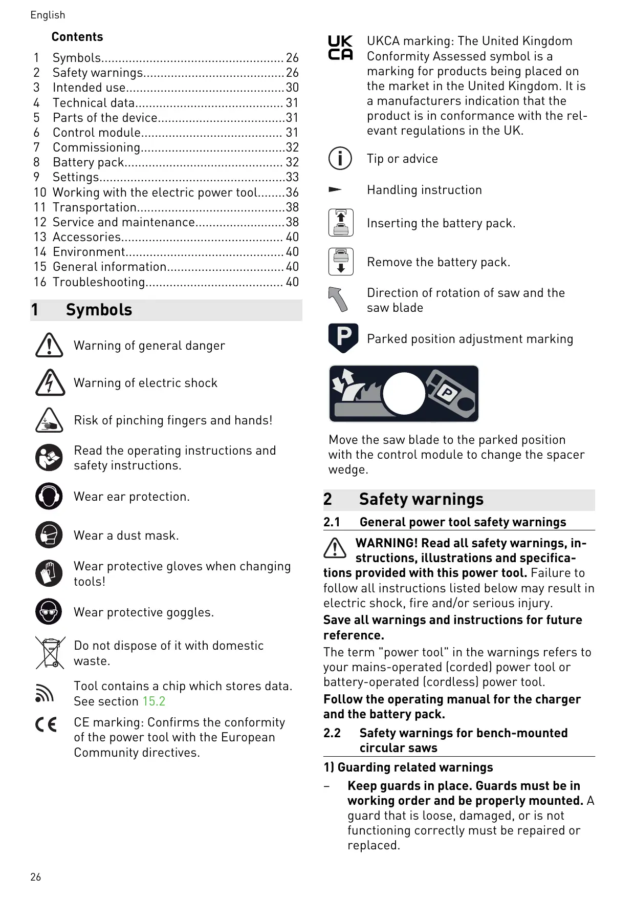
10.8 Removing blockages [15]
![FESTOOL CSC SYS 50 EB-Basic - Removing blockages [15] - 1](/content/2024/12/326157/images/80e887af43b260b3b2d5f22606253228e42cd66464b0238182d719e6eaa6b8e0.jpg)
WARNING
Risk of injury
- Switch the power tool off at the main switch and remove the battery pack from the power tool before performing any work on the power tool.
Remove the cover plate (see Section 9.16).
English
Unlock and swivel the saw blade flap [15-1] downwards.
CAUTION! Wear protective gloves.
Remove any remaining parts of the workpiece and use an extractor in the area around the saw blade.
- Close the saw blade flap and fit the cover plate.
Insert the hex key into the holder [1-10] provided.
11 Transportation

CAUTION
Risk of injury!
The power tool may slip out of your hands when you are carrying it.
Always carry the power tool with both hands, using the gripping surfaces [1-1] provided on both sides of the power tool.
- When carrying with the carrying handle [1-24], ensure that the lid is secured with both locking clips.

CAUTION
Risk of injury
The sliding table may extend. The extension table may unfold.
The power tool must always be transported in the transport position that has been provided for this purpose.
11.1 Securing the power tool (transport position)
- Move the saw blade to the parked position with the control module (select favourite "P").
Use the main switch to switch off the power tool (see section 7.3).
Lock the sliding table in position (see section 9.13). - Fold the extension table (see section 9.11).
Push the stop rails together until the two adjustment markings for the parked position (see section 1) are facing each other.
Put the parallel side fence on the power tool in parked position [16B].
Stow the spacer wedge with protective cover and the remaining accessories in the lid [16A]. The preset profile setting rail can also be attached to the power tool in parked position [16B]. - Close the lid and secure it with the two locking clips.
The power tool is in the transport position.
12 Service and maintenance

WARNING
Risk of injury, electric shock
Always remove the battery pack from the power tool before performing any maintenance or service work.
- All maintenance and repair work which requires the motor housing to be opened should always be carried out by an authorised service workshop.

Customer service and repairs must only be carried out by the manufacturer or service workshops. Find the nearest address at:
www.festool.co.uk/service
Always use original Festool spare parts. Order no. at:
www.festool.co.uk/service
Damaged safety devices and components must be repaired or replaced in a recognised specialist workshop, unless otherwise indicated in the operating instructions.
To ensure constant air circulation, always keep the cooling air openings in the housing clean and free of blockages.
Use an extractor to remove dust deposits, splinters and chips (see section 10.8).
- Do not grease or oil spindles for height and angle adjustment.
12.1 Adjusting the extension table height
Image [17]
12.2 Adjusting the sliding table height [18]
If the height of the sliding table no longer matches the height of the plate:
Move the sliding table into the front position.
Remove the cover cap [18-1] and undo the screw underneath it.
Move the sliding table into the back position.
Remove the cover cap [18-2] and undo the screw.
Adjust the height of the sliding table with the adjusting screws [18-3] and [18-4].
Turn to the right = lower
Turn to the left = lift
- Tighten the screws [18-1] and [18-2] (3.5 Nm) and fit the cover caps.
12.3 Adjusting the maximum sliding table lift [19]
If the sliding table can no longer be moved across its maximum adjustment range:
- Manually (using force) move the sliding table to its front and rear end positions until the edge of the sliding table is positioned at the lift markings [19-1].
12.4 Cleaning the sliding table tracks [20]
If the sliding table is difficult to move, this may be due to dirt in the sliding table tracks or in the ball bearings.
Clean the four tracks in the sliding table guide [20-1] and the four tracks on the sliding table [20-2] with a cloth.
If the sliding table is still difficult to move, contact the manufacturer or an authorised service workshop.
12.5 Adjusting the preset profile setting rail
Adjusting the perpendicularity:
Image [21]
12.6 Cleaning the end stops [22]
If the reference movement fails: Clean the end stops of the height and angle adjustment.
Move the saw blade to the top position.
Set the cutting angle to 0^ .
Use the main switch to switch off the power tool and remove battery packs.
Unfold the extension table.
1 Remove the service flap [22-1].
3 Clean the bottom height [22-3] and angle [22-4] end stops with a brush.
Insert the service flap and tighten it with the screw [22-2].
Insert battery packs and switch on the power tool at the main switch.
Move the saw blade all the way down.
Use the main switch to switch off the power tool and remove battery packs.
Remove the service flap [22-1].
Clean the top height [22-5] end stops with a brush.
Insert the service flap and tighten it with the screw [22-2].
Remove the cover plate (see Section 9.16).
Clean the angle end stops [22-6] + [22-7] with a brush.
Fit the cover plate.
If you experience problems with this procedure, contact an authorised service workshop or the manufacturer.
12.7 Aligning the parallel side fence with the saw blade [23]
In case of splintering on the top side of the workpiece left of the saw blade (on the side of the preset profile setting rail)
Turn in the screw [23-1].
The parallel side fence moves in direction A .
In case of splintering on the right-hand side of the saw blade (on the side of the parallel side fence)
Turn out the screw [23-1].
The parallel side fence moves in direction B .
One turn of the screw [23-1] corresponds to a movement of approx. 3.1 mm in direction A or B.
It may be necessary to readjust the clamping force of the parallel side fence (see Section 12.8).
- Turn in the screw [23-1]: The clamping force needs to be reduced.
Turn out the screw [23-1]: The clamping force needs to be increased.
12.8 Adjusting the clamping force of the parallel side fence [24]
- Turning in the screw [24-1] increases the clamping force.
- Undoing the screw reduces the clamping force.
12.9 Aligning the sliding table with the saw blade [25]
- Move the sliding table into the front position and lock it there.
Remove the cover cap [25-1].
Press on both points to release.
Pull off the cover cap.
Remove the cover cap [25-2] and slightly undo the screw underneath it.
Move the sliding table into the back position.
Remove the cover cap [25-3] and slightly undo the screw underneath it.
- Adjust the free cut with the screw [25-4]. NOTICE: Do NOT adjust the screw [25-5]. Otherwise, the sliding table will not move easily.
6 + tightenscrews.
Fit all cover caps again.
13 Accessories
Refer to the Festool catalogue for the order numbers of accessories and tools or find them online at www.festool.co.uk.
14 Environment

Do not dispose of the device in the
household waste! Recycle devices, accessories and packaging. Observe appli-national regulations.
Before disposal, users must remove discharged batteries, accumulators that are not enclosed by the device and lights that can be removed from the old device without causing damage, if these are present. The old batteries and rechargeable batteries can then be recycled systematically.
In accordance with the European Directive on waste electrical and electronic equipment and implementation in national law, used power tools must be collected separately and handed in for environmentally friendly recycling.
Information on collection points for proper disposal can be found at www.festool.co.uk/ recycling.
Information on REACH: www.festool.co.uk/
reach
15 General information
Imported into the UK by
Festool UK Ltd
1 Anglo Saxon Way
Bury St Edmunds
IP30 9XH
Great Britain
15.1 Bluetooth®
The Bluetooth® word mark and the logos are registered trademarks of Bluetooth SIG, Inc.; they are used by TTS Tooltechnic Systems AG & Co. KG, and therefore by Festool, under licence.
15.2 Information on data privacy
The power tool contains a chip which automatically stores machine and operating data. The data saved cannot be traced back directly to an individual.
The data can be read in a contactless manner using special devices and shall only be used by Festool for fault diagnosis, repair and warranty processing and for quality improvement or enhancement of the power tool. The data shall not be used in any other way without the express consent of the customer.
16 Troubleshooting
| Problem | Possible causes | Remedy |
| The display does not come on. | One or both battery packs are discharged. | Charge the battery packs. |
| Incorrect battery pack used. | Use suitable battery packs (see section 4). | |
| The display does not show anything. | Display fault. | Contact an authorised service workshop or the manufacturer. |
| Display texts in the wrong language. | Call up the lowest entry in the main menu. Then select the required language there. | |
| The display shows a warning. | Warning, e.g. due to overheating. | Observe the info text in the dialogue box and ac-knowledge the message via the focus line. |
| The display shows a failure. | The power tool is attempting to solve a problem, e.g. overheating. | Follow the instructions on the display. |
| The power tool is faulty. | Contact an authorised service workshop or the manufacturer. | |
| Status LED flashes red. | Incorrect battery pack combi-nation inserted. | See Section 4. |
| Undervoltage upon system start (battery level too low). | Replace the battery pack. | |
| The Systainer hood does not close. | Accessory parts are not in the parked position. | Move the power tool to the transport position (see Section 11.1). |
| The hex key cannot be inserted into the opening on the type plate. | The saw blade is not in the parked position. | Move the saw blade to the parked position with the control module (see section 9.8). |
| The cutting angle does not match the indication on the display. | Cutting angle shifted. | Calibrate the cutting angle (see section 9.7). |
| The cutting height does not match the indication on the display. | Cutting height shifted. | Calibrate the cutting height (see section 9.5). |
| Reference movement failed | An area cannot be reached. End stops dirty. | Clean the end stops (see section 12.6). |
| The sliding table and plate are not at the same height. | Sliding table height shifted. | Adjust the height of the sliding table (see section 12.2). |
| The extension table and plate are not at the same height. | Extension table height shifted. | Adjust the extension table height (see section 12.1). |
| The sliding table can no longer be moved fully into both positions. | Maximum lift shifted. | Adjust the maximum sliding table lift (see section 12.3). |
| The sliding table is difficult to move. | Dirty tracks. | Clean the tracks with a cloth (see section 12.4). |
| Ball bearings dirty. | Contact an authorised service workshop or the manufacturer. | |
| Splintering during saw-ing | The parallel side fence for free cuts has shifted. | Alignin the parallel side fence to the saw blade (see section 12.7). |
| Motor runs with reduced power | Motor temperature too high. Speed has been reduced to allow the ventilator to cool the motor quickly. | The power tool starts up again automatically once the motor has cooled sufficiently. Only continue working once cooling down has concluded. |
Sommaire
[1-6] Table coulissante
[2-11] Position de rangement favorite
m = 311
Spouwmes monteren [4C]
2.5 Aluminiumbearbetning
Bageste position A, billed [10]
Savklingeskifteposition
Forreste position B, billed [10]
www.festool.com/QuickGuide-CSCSYS
9.1 Innstillinger på betjeningsmodulen
9.3 Stille inn turtallet
9.4 Stille inn snithothyden
Still inn snithdyden pa betjeningsmodulen.
Chamar o menu principal
IcnoIb3yIte 3aIHTbIe HayuHnKn!

Pa6oTaIeBpeCnIpaTope!

YcTaHOBnTe aKKymyJIaTOp.

OToeHnHTe aKKyMnyTOp.

Haprablenie BpauneHnI nnIb-Horo dNcKa

KoHTpoJIbHbIe MeTKe Hepa6OeRo nOIo-JXeHnIa

Ipepe 3aMeHo np3XmHOro KInHa nepeVe- dnte pNlBnB I nck B Hepa6Oee noLoxKeHne uepe3 ynpabJIouuM MoDyIb.
2 Yka3aHnI NO TexHnKe 6e3OpacHoCTn
2.1 06uzne yka3aHnno ToTexHnke 6e3oNaChOCTnДЯ 3JIeKTPoHHCTpymEHTOB

OToeHnHTe aKkymyIaTOp.
[3B]

BcTaBbTe aKKymyIaTOp -do _N_C_un
i 3Kcnpnyatauna 3JIeKtpOnHCTpyMeHTa BO3-MoXHa T0JIbKO C DByMЯ aKKyMylTOpamNdoCTaToUHOJ 3apAHDnO JEMKOCTn. IOnxOJa-7Ine aKKymyJrTOpbI, CM. pa3dE14.
YpoBHeB 3apJa aKKymyIaTopa BbIBOHTcHa DnCnJIe N B npInoJKeHn Festool Work. Homepa aKKymyIaTOpOB [3B-1] yKa3aHbI pIaOM c pa3-bEMaMn dJa aKKymyIaTOpOB.
i Iopno6hna nHphiOpMaunra 03apAnHom ycTpoIcTBe n aKKyMylrTope c HndnKaTopoM EMKoCTNu CoepKntC8 B COOTBeTCTByUOx npKOBODCTBax No 3KcnnyaTaun.
9 Hac troponk

YcTaHOBka pa3XKMnHOrO KInHa [4C]
BcTaBbTe pa3XmHoi KInH cBepxy do ero 0Kcaun. OCTOPOXHO! Onacnoctb TpaB-
MnpoBaHnra! PpOBepe TaedEeXHoCTb KncCa- cHn pa3KmHOrO KInHa.
9.10 ПыileydaJIeHne

PPEДУПЕЖДECHNE
K NaTpy6ky [5-2] MoJHo NODcoeHNHTb NblJeYdaJIaHOuN annapaT Festool co BCacbIBaHOuM ShlaHrom dHaM. 27 MM MM.
CoeHnHTeBbIeJMeHrBCaCbBaIOUeRo ⅢaHra BCTaBJIeTcB CoeHnHTeBbIeJMeHr [5-2].
BHMAHNE!Прииспользовани He aHTnCTaTtueckoroШланга BO3MOxHNo HakOpIeHne CTA-TtueckoroЗapЯДa,Вpe3yIbTaTeЧero ПОь3O-BaTeJIb MoKET NOJUChTb YdAp 3JIeKTpIeCKIM TOKOM,a 3JIeKTpOHHBe KOMNoHENTbl 3JIeKTpOHH-CTpyMeNTa - NOBpeKdEHN.
9.11 Pacunpntel nltb-ocHOBaHn [6]
Дя уBELHENЯ pa6oey NOBepxHocTи npi npoJIObHOM ПЛeHn OTe 95 MM MM.
1 2 Pa3IoXnTe paCUnpTeIb PInTbI-oc-HOBaHnI.
3 Cnojntepacwnpntb nIITbI-ocHOBaHn.
9.16 3aMeHa nIIbHOro dNcKa

ПЕДУПЕЖДЕНЕ
Onachoctb TpaBMnpoBaHn
IpeenIO6bIMn pa6oTaMn Ha 3JeKtpOnH-CTpyMeHTe BblKlOuaTe ero rlaBHBIM BblKlOuataJIem N OTCoeDINHJrTe aKKyMyJrTOp.

BHHMAHNE
UctahOBKa NnIbHOrO DnCKa
OCTOPOXHO! PpOBepbTe BnHTbI n ΦlaHeu Ha OTCyTCTBVe 3aqr3HEnn n IcNoJIb3yIte TOnJIbKO YnCTbIe n HEnOBpeKdEHHbIe DeTaII!
BCTaBbTe HOBBI INCKI HApyXhBI JIaHeU. OCTOPOXHO! HnpaBJIeHn BpaIeHn IINbHOro DnCKa [14-5] nPiJIbI [14-6] DoJxHbI COBpAdaTb! Ppi Heco6JIouDeHn 3ToRo npabNla BO3MOxHc cepbE3Hoe TpaBMnpoBaHne.
Ipn BCTaBHeHOM IINcKe HaIINcB Ha HEm He BnHa.
3aTaNHTe BnHT (IeBaJ pe3b6a).
BcTaBbTe n 3aTaNHe 3aUHTHyO KpbI- shKy [14-8].
BcTaBbTe pa3KmHOn KJInH.
Blojnte kIou-WectnrgpanHK B npedycmoTpeHbI dIy Hero depxkateIb [1-10].
10 Pa6oTa c 3JIeKTpOuHcTpyMeHTOM
10.1 Be3onacHocTb B pa6oTe

Peped Haayalom pa60tbi
- y6eIntecb B TOM, qTO 3aIHTbI KOKyX nnIbHOrO dNcKa He nOBpeKdEHN He Ka-caETcA dNcKa npn IIO6OM yIge N npn IIO6oB rIy6uHe pe3a. KpbIshKn Ha 3aIANTHom KOKy-Xe nnIbHOrO dNcKa dOJxHbICBO6OdHO DBNrATbcra.
- CToI, 3aUHTHa KpbIuKa n BcTaBka c npope3bIO dJIa PnIbHOrO DnCKa He DoJXHbIMeTb NOBpeKdEHN (HaPpImep 3a3y6pnH B npope3n). NOBpeKdEHHbIe DeTaNn PoJNe-JxKat 06a3aTeJbHO 3aMeHe.
- HnkoTda He pa6oTaIte 6e3 3aunTHoN KpbI- shKN, cepBnCHoN KpbIshKN IN BCTaBKn C npope3bIO DnI PnIbHOrO DnCKa.
- Пюверьтейнаджноctь посадкпильноюдиска.
BHIMAHHE!Onachoctb neperpeBa!Pepepa6otoi npoepeyTe HaedxHoctb fHK- caunn aKKymyIaTopa. - ПоложиTe 3aroToBky poBHo, 6e3 3aXmMa.
BoBpempa6oTbI
- Onachoctb onpOKnDbIbAHna! Ppi o6pa6oTKe KpyHpOpa3MepHbIX INI CNIIKOM TjXe-
ЛьIx 3aToTOBOK эл ektpoHCTpyMeHT может OпрokнHytbcя.
Pa6oTaIe 6e3 3aIHTbIX nepuAtok. NnIb-HbI JnCK MoKeT 3aXbATITb nepuATky n 3a-TaHyTb pyKy IOD INCK.
- Правильhoe pa6очee поожени: Ha cToPoHe NOДВИЖНOrO CTОЛа ряДOM C ЛИнnei pe3a.
- OnpaHocTb TpaBMnpoBaHnOtJeTaUoUmN DeTaJIaMn CToaUx PraDom IIOJeN. JePKeIte DInCTaHcNIO.
BbIbIpaIe npaBnIbHyO cKOpocTn noJaun, UTo6bl He Doynctntb nepeRpeBa peJxuX KpOMOK nIbHOro DnCKa N OJIaBLeHnA nnactka npn erO o6pa60Tke. Yem TBePKe paCnnIINBaEmbI MaTePnaI, TeM HnKe dOnJxHa 6bITb cKOpocTb noJaun.
- HnKoTda He n3MeHЯITe pIoJoxKeHne 3JIeK-TpOuHCTpyMenta npBpaUaIOUeMcra NIIb-HOM DnCKe.
Korda Bbl He noIb3yeTecb TOnKaTe- Iem [1-12], xpaHnTe erO BOTceKe (Pnc. 1).
10.2 CnocobI npImeHHeN
MOHTaXHyIO DnCKOByIO PnIy
C3aCTOIpoEHHbIM IOBnXHbIM CTOJOM INpOdoJIbHbIM ynpOpM.
10.3 TopceBaHne
BbIopHЯTe TOpueBaHHe n pe3bI pOJ yrIom HaJIeBoi cTOpOHe 3JIeKtpoINHcTpymEHTa. BcerdaNcPOnb3yInTe yrIIOBOi paCTpOBbI ynpO (cm. pa3-DeI 9.14).
10.4 Pe3 noj yrnom
Pn BbIOpHHeHH npOHNIOB NOyrglOM nC- PnIb3yIte pa3XHMHO KJINH C 3aUHTbIM KOxYxOM (cm. pa3d. 9.9).
CHMnTe npaJIneIbHbI ynp.
YcTaHOBnTe yrIIOBoi pactpoBbI ynpHa noDvIXHOM cToJe (cm. pa3Je9.14).
0cna6bTe fHKcaTOp nOdBnKHO rO cToJa (cm. pa3Je9 9.13).
- Beñnte 3afoToBky no yrIIOBOMy pactpoBOMy ynpy.
10.5 PpOoJbHbIe npOnnJIbI
YcTaHOBnTe pa3KmH0n KJIuH C 3aUHTbIM KOxuyXOM (cm. pa3d. 9.9).
- Chnmte yrnoBoi paTpoBbI ynp (cm. pa3-9.14).
YcTaHOBnTe npaJIeJIbHbI ynp (cm. pa3- 9.12).
BbIOnHnTe npoDoJIbHbI npOIIJ.
10.6 Kocbie npoioNbHbpe3bl
IcnoJb3yIte pa3KIMHOJ KJIINH c 3aUNTHbIM KOxUxOM (cm. pa3d. 9.9).
- Chmnte yrnoBoi paTpoBbI ynp (cm. pa3-9.14).
YcTaHOBnTe npaJIeJIbHbI ynp (cm. pa3- 9.12).
Ecni nIbHbI dNcK hKnloHb B cToPOHy npaJIeIbHOrO yNopa [9B]:
- He BxOДT B KOMПЛЕKT NOCTaBKN.
10.7 HeCKB03HbIe npoINJIbI

ПЕДУПЕЖДЕНЕ
Onachoctb HeccaCTHOro clyua npn OTdaue
Cpa3y no OKoHuaHn pa60T, KOToPbIe Bbl- pOJIHЯOTc8e3 pa3XIMHOrO KJIHa c 3a- uHTbI KoxyXOM, o6raTeJbHo BepHnte Ha MeCTo pa3XIMHOrKJInH.
CnoxHbIe cnooc6bl 6pa6oTKn, KaK HapnpMep Bpe3Hoe nIleHne nn BbIOJHeHne BbIKpyKKn, HeOyCTmbl.
i IЯ BbIIOJIHeHnI HeCKB03HbIX npOJIIOB nCpOJIb3yIte npJxM-rge6EHNKy*,uTo6bl BO BpeM npOIIa OHa npJxMmaJa 3aToTOBky K cToIy.
- He BXOДNT B KOMПЛЕKT NOCTaВКИ.
EcnBbICota NOdBnXHOrO CToJa OTKIOHJIacbOT BblcOTbl NNITbI-OCHOBaHnA:
CdBnHbTe POBBnXhbl CToI B KpaHnepeDHee PNOJoxHeNe.
BbInbTe 3aIyUkU [18-1] n ocIa6bTe BnHT noI Hei.
Cdbnhte noBnKhblcToI B KpaHHe 3a- dHee noloxehne.
BbInbTe 3aIyUkU [18-2] n ocla6bTe BnHT.
IoppeynpuTe BbICOTy noBnKHOcToJa C NOMOJIbOppeYIpOBoHbIX BNHTOB [18-3] n [18-4].
BpaueHne BnpaBo = onyckaHne
BpaueHne BJeBO = NOdHMaHne
3aTaNHTe BnHTbI [18-1] n [18-2] (3,5 H·M) uYCTaHOBNTe 3aRnyuKn.
8.1 Ukazatel capacity

- Inhaltsverzeichnis
- Symbols
- Safety warnings
- General power tool safety warnings
- 2) Cutting procedures warnings
- 3) Kickback causes and related warnings
- Safety instructions for the pre-assembled saw blade
- Usage
- Installation and mounting
- Service and maintenance
- Further safety instructions
- Sawing aluminium
- Other risks
- Emission levels
- CAUTION
- Noise generated when working Risk of damage to hearing
- The emission values may deviate from the specified values. This is dependent on how the tool is used and the type of workpiece being machined.
- Intended use
- Saw blades
- Technical data
- Parts of the device
- Control module
- Elements of the control module
- Display elements
- Commissioning
- Setting up the power tool
- WARNING
- Risk of accidents
- Power tool tips over on uneven surface.
- Initial commissioning
- Switching on/off
- Switching on the power tool
- Switching on the saw blade
- Switching off the saw blade
- Switching off the power tool
- Battery pack
- Capacity indicator
- Settings
- Settings on the control module
- Navigating
- Selecting
- Festool Work App*
- Setting the speed
- Setting the cutting height
- Calibrating the cutting height
- Adjusting the cutting angle
- Risk of crushing
- When adjusting the cutting angle, the extraction channel also moves.
- Calibrating the cutting angle
- Favourites
- Selecting a favourite
- Saving favourites
- Spacer wedge
- Risk of injury
- Spacer wedge with guard [1-12]
- Non-through cutting spacer wedge [1-11]
- Removing the spacer wedge, option 1 [4A]
- Removing the spacer wedge, option 2 [4B]
- Fitting the spacer wedge [4C]
- Dust extraction
- Health hazard posed by dust
- Independent extraction
- Festool mobile dust extractor
- Extension table [6]
- Parallel side fence
- Fitting the parallel side fence
- Setting the cutting width for rip cutting
- Adjusting the stop rail [9-1]
- Adjusting the sliding table
- Working position
- Saw blade change position
- Preset profile setting rail
- Risk of accidents due to tools
- Fitting/removing the preset profile setting rail
- Setting the angle
- Adjusting the stop rail side position
- Selecting the saw blade
- Changing the saw blade
- Risk of injury from hot and sharp insertion tool
- Removing the cover plate
- Removing the saw blade
- Fitting the saw blade
- Working with the electric power tool
- Safe working
- Before starting
- During work
- Types of use
- Cross cuts
- Angled cuts
- Rip cuts
- Mitre rip cuts
- Non-through cutting
- Risk of accidents due to kickback
- Grooving
- Rabbeting
- Removing blockages [15]
- English
- Transportation
- Risk of injury!
- The power tool may slip out of your hands when you are carrying it.
- The sliding table may extend. The extension table may unfold.
- Securing the power tool (transport position)
- Service and maintenance
- Risk of injury, electric shock
- Adjusting the extension table height
- Adjusting the sliding table height [18]
- Adjusting the maximum sliding table lift [19]
- Cleaning the sliding table tracks [20]
- Adjusting the preset profile setting rail
- Cleaning the end stops [22]
- Aligning the parallel side fence with the saw blade [23]
- In case of splintering on the top side of the workpiece left of the saw blade (on the side of the preset profile setting rail)
- In case of splintering on the right-hand side of the saw blade (on the side of the parallel side fence)
- Adjusting the clamping force of the parallel side fence [24]
- Aligning the sliding table with the saw blade [25]
- Accessories
- Environment
- Do not dispose of the device in the
- General information
- Imported into the UK by
- Bluetooth®
- Information on data privacy
- Sommaire
- Spouwmes monteren [4C]
- Aluminiumbearbetning
- Savklingeskifteposition
- Innstillinger på betjeningsmodulen
- Stille inn turtallet
- Stille inn snithothyden
- Yka3aHnI NO TexHnKe 6e3OpacHoCTn
- 06uzne yka3aHnno ToTexHnke 6e3oNaChOCTnДЯ 3JIeKTPoHHCTpymEHTOB
- Hac troponk
- YcTaHOBka pa3XKMnHOrO KInHa [4C]
- ПыileydaJIeHne
- PPEДУПЕЖДECHNE
- Pacunpntel nltb-ocHOBaHn [6]
- 3aMeHa nIIbHOro dNcKa
- ПЕДУПЕЖДЕНЕ
- Onachoctb TpaBMnpoBaHn
- BHHMAHNE
- UctahOBKa NnIbHOrO DnCKa
- Pa6oTa c 3JIeKTpOuHcTpyMeHTOM
- Be3onacHocTb B pa6oTe
- Peped Haayalom pa60tbi
- BoBpempa6oTbI
- CnocobI npImeHHeN
- TopceBaHne
- Pe3 noj yrnom
- PpOoJbHbIe npOnnJIbI
- Kocbie npoioNbHbpe3bl
- HeCKB03HbIe npoINJIbI
- Onachoctb HeccaCTHOro clyua npn OTdaue
- Ukazatel capacity
Brand : FESTOOL
Model : CSC SYS 50 EB-Basic
Category : Table saw