
FM 6990 E - Drill KRESS - Free user manual and instructions
Find the device manual for free FM 6990 E KRESS in PDF.
| Product type | Drill / motor unit for milling and grinding |
| Brand | KRESS |
| Model | FM 6990 E |
| Power consumption | 900 W |
| Output power | 495 W |
| No-load speed | 8000-26000 rpm |
| Tool holder | Clamping collet Ø 8 mm |
| Max. milling diameter | 30 mm |
| Max. grooving tool diameter | 40 mm |
| Weight | 1.6 kg |
| Supply voltage | 230 V (according to rating plate) |
| Protection type | Double insulation (international symbol) |
| Electronic speed control | Full wave with tachogenerator |
| Main functions | Milling, grinding, drilling, polishing, flexible shaft drive |
| Soft start | Yes (starting current limiter) |
| Electronic overload protection | Yes (automatic speed reduction) |
| Spindle lock | Yes (by pressing the push button) |
| Protective cover | Yes (mounting plate and protective cover) |
| Mains cable type | Removable module (push-button locking) |
| Included accessory | Visual protection plate |
| Maintenance | Blow out dust, keep vents clear, lifetime lubrication |
| Sound pressure level | 78 dB(A) (emission value at work station) |
| Vibration acceleration value | 6.1 m/s² |
| Warranty | 24 months (manufacturing and material defects) |
Frequently Asked Questions - FM 6990 E KRESS
User questions about FM 6990 E KRESS
0 question about this device. Answer the ones you know or ask your own.
Ask a new question about this device
Download the instructions for your Drill in PDF format for free! Find your manual FM 6990 E - KRESS and take your electronic device back in hand. On this page are published all the documents necessary for the use of your device. FM 6990 E by KRESS.
USER MANUAL FM 6990 E KRESS
Routing and grinding motor
Operating Instructions
F
Schaldruckpegel: FM 6955 = 75^+3 dB (A
FM 6990 E = 74,5 ^+3 dB (A)
FM 6990 E = 87,5+3 dB (A)
Emissionswert: FM 6955 = 78+3 dB (A)
FM 6990 E = 77,5+3 dB (A)
| Technical data | FM 6955 | FM 6990 E |
| Input watts | 550 | 900 |
| Output watts | 310 | 495 |
| Idle speed min-1 | 28 000 | 8000 - 26 000 |
| Tool mounted in collet dia mm | 8 | 8 |
| Cutter dia max. mm | 30 | 30 |
| Grooving cutters max mm | 40 | 40 |
| Weight approx. kg | 1.5 | 1.6 |
Use
The milling motor is universally suitable for use as a recessing and shaping machine in a drill jig or on a drilling and milling bench (in conjunction with a milling machine table if possible) performing all milling work on wood, coated wood and plastics when the prescribed milling tools are used. It is also suitable as a hand grinder and as a drive unit for high-speed flexible spindles.
Safety instructions and prevention of accidents
Before operating the machine, please read through the operating instructions completely, follow the Safety Instructions in this manual as well as the general Safety Instructions for Power Tools in the accompanying booklet.
Caution!
- Pull mains plug prior to working on motor. This applies above all to clamping of cutters or all other tools and during service jobs.
- Hold tools well or clamp.
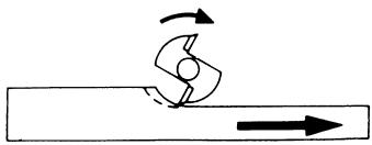
- Feed the work always against direction of rotation of cutter (up-cutting). Important when cutting along edges.
- Make sure that the cutting tools are always sharp. Blunt tools result in poor cutting and unnecessary overload of motor.
- A uniform and not too excessive feed will extend life of cutter, will prevent burns on wood and protect motor against overloads.
- Attention! Do not move fingers into range of cutter!
- Make sure that tool is switched off when putting motor aside.
- Pull mains plug as a protection against unauthorized operation whenever the work is interrupted for extended periods.
The spindle must not be clamped in the vice. - The milling motor is designed for counter-clockwise rotation. Clockwise operation is prohibited.
- Clamp the milling motor on the clamping collar with a round-type flange around the entire circumference (Eurohals - Euro-collar). Clamping at specific points destroys the bearing.
For more demanding applications, the tool must be secured at the spindle and ternsion nut with two 14/22 size wrenches.
- Do not work with materials containing asbestos!
- Outside power sockets must be protected with residual-current-operated circuit-breakers (r.c.c.b.).
- Do not drill holes into the housing to label the machine. The protective insulation will be bridged. Please use self-adhesive labels.
Always lead cables away towards the back of the machine.
Double insulation
Our equipment is designed in accordance with European regulations (EN standards) for the utmost safety of the user. Machines with double insulation always carry the international l symbol. The machines do not require earthing. A two-core cable is sufficient.
The machines are interference-suppressed in accordance with EN 55014.
Initial operation
Before the first operation check that the mains voltage corresponds to that given on the machine nameplate.

Tool clamping
The milling and grinding motor spindle (1) is equipped with a precision collet chuck (2) to mount the tools (3). A spindle catch makes the tightening and loosening of the clamp nut (4) easier. To mount the tools (3), the motor spindle (1) is stopped when the pusher (5) is pressed in. The clamp nut (4) is tightened with a size 22 fork wrench. The motor spindle (1) is stopped again to remove the tools (3). The collet chuck (2) is first loosened with one rotation of the clamp nut (4) using the fork wrench and the tool (3) can be removed after additional rotations.
Collet change
An annular spring (6) holds collet chuck (2) in clamp nut. Energetic pulling will release collet chuck (2) from clamp nut (4). Apply heavy pressure to engage new collet chuck and clamp nut (4).
Attention!
Never tighten clamp nut when no tool is inserted. Collet chuck might be compressed excessively and suffer damage.
Attention!
Before mounting tools, disconnect the machine from the power supply, or remove the mains cable module (17) from the casing using the locking device button (18).

Switching machine on and off
The machine is started by sliding switch ring (7) in the direction of the arrow. The toggle lever (8) will then automatically engage in the foremost slide position. Pushing on the tilted front edge (9) of toggle lever (8) disengages the switch and causes the switch ring (7) to rotate back into its original position automatically. The machine comes to a standstill.
Adjustment of cutting depth
Refer to relevant information in operating instructions for your drilling rig or drilling and cutting unit.

Guard
The mounting plate (10) for guard (11) is inserted between the motor and the arm of the drilling rig. The 4 rubber supports ( 6× 3) are pushed into the mounting plate (10) drill holes. They ensure torsion-safe fastening. Clamp motor into mounting bracket of drilling rig. Screw guard with cylinder head screws (14) to mounting plate (10) while adding washers (12) and snap rings (13). The guard (11) is provided with 2 bores on both sides to permit complete swivelling up of guard (11) in relation to the different mounting brackets of drilling rigs (make sure the correct bore is selected).
Working with routing (cutting) motor
When using a drilling rig or a drilling and cutting unit - in combination with a cutting table, if required - pay attention to the information enclosed in the operating instructions. Also make sure that the fences are set as closely as possible against the milling cutter and that the cutter guard is set down as closely as possible in direction of work surface, while also making sure that the equipment used for cutting jobs always guarantees safe guiding of the work, for example fence, auxiliary stop, feeding slide or anti-kickback device during routing jobs.
Always select feeding direction of work against direction of rotation of cutter (up-cutting):
Attention!
Never employ down-cutting!
4
Free-hand work
The milling and grinding motor is ideally suited to many kinds of free-hand work due to its small size and light weight. The handle (15) (special accessories) makes it easy to use.
Attention! Always wear safety goggles! Switch off motor immediately at end of work as a safety measure against injuries!
Use only routing, drilling, polishing and grinding tools licenced for high-speed operation (30 000/min.)
Sanding/grinding jobs
When using routing and grinding motor for manual sanding and grinding jobs, make sure that a circumferential speed of 45m / s is not exceeded.
The circumferential speed is calculated as follows:
$$ V = \frac {d \cdot \pi \cdot n}{6 0 0 0 0} $$
V = Circumferential speed m/s
d = sanding/grinding wheel dia. in mm
= 3.14
n = idle speed of routing and grinding motor in rpm.
Example: Diameter of sanding/grinding wheel is 25mm
$$ V = \frac {2 5 \cdot \pi \cdot 2 4 0 0 0}{6 0 0 0 0} \frac {m}{s} = 3 1. 4 \frac {m}{s} $$
The permissible maximum speed is not exceeded.
The maximum permissible circumferential speed is attained at a sanding/grinding wheel diameter of 30mm
Do not use larger wheels.
Make sure that
- the sanding/grinding wheels used are ceramic or resin-bonded
- you store sanding or grinding wheels in such a manner that they cannot be damaged (cracks in wheel, damaged tool shanks etc. are dangerous to operator)
- prior to using new sanding or grinding wheels, a test run of at least 5 minutes without load is performed.
Working with flexible shaft
Thanks to its high speed the routing and grinding motor is also excellently suited for driving a flexible shaft.
Permissible idle speed of the flexible shaft must be adapted to the idle speed of routing and grinding motor.
Attention! Wear safety goggles!
Full-wave control electronics with electronic motor protection monitoring (safety electronics)
The following advantages are integrated into the full-wave control electronics with built-in motor tachogenerator:
Gentle warm-up
Limitation of starting current reduces the inrush current. The motor starts up slowly until reaching the preset speed, thus protecting the user and prolonging the life of the machine.
Electronic overload protection
The speed of the milling motor is reduced by the integrated motor monitoring should the load become too high for the motor. The load on the machine must be reduced. Ideally, the machine should be removed from the work piece briefly so that full capacity is regained.
Electronic control with tachogenerator
The full-wave control electronics makes possible a large control range of 8000 - 26 000 rpm^-1 . The tachogenerator provides power reserve under stress. The pre-set rotational speed remains constant. By using the full-wave control electronics' adjustment dial (16), the optimal cutting speed or working rotational speed can be adjusted regardless of:
- material (hard woods, soft woods or plastics)
- milling or grinding tool (small diameter, lower or higher quality).
- The required cutting or working rotational speed depends on many factors (varying degrees of hardness of the material being machined, milling quality, infeed, etc.). The optimal adjustment must be determined by trial and error when beginning work.
Caution!
Very high speeds mean rapid wear and a short working life for your tools!
Important! Use only sharp and well-preserved cutting tools! Best of all use our original cutting tools!
When using other cutting tools the speeds per minute which have been durably marked by the manufacturer on the turning tools must not be exceeded!
Replacing carbon brushes
Our service personnel will do this and all other servicing work quickly and professionally.
Mains cable
Damaged mains cables must not be used. They are to be replaced immediately.
This has been made very straightforward by the new mains cable module (17). Press both locking keys (18) and pull the mains cable module (17) out of the handle. Insert the new mains cable into the handle and lock in place. Different lengthed mains cables are available as special accessories.
Only use the mains cable module for KRESS power tools! Do not attempt to operate other electrical appliances with it!
Motor, cleaning and care
The powerful universal motor has adequate power reserves. For a long life, be sure to blow dust out of housing after each job. The vent holes should always be kept unobstructed and clean since uniform ventilation is extremely important. The machine is lubricated for life and widely maintenance-free.
Tool care
Make sure that only well-maintained cutting tools are used. This will protect the motor and extend the life of the machine. Carbide-tipped cutters require special, careful treatment since the cutting edges are easily subject to chipping.
To eliminate any risk of injuries, the use of damaged cutting, grinding and polishing tools on our high-speed cutting and grinding motor is no longer permitted.
Noise/vibration information
Measured values correspond with EN 50144.
Sound pressure level: FM 6955 = 75^+3 dB (A)
FM 6990 E = 74.5+3 dB (A)
Sound power level: FM 6955 = 88^+3 dB (A)
FM 6990 E = 87.5+3 dB (A)
Work place
emission value: FM 6955 = 78^+3 dB (A)
FM 6990 E = 77.5 ^+3 dB (A)
Operators require noise protection equipment.
The weighted acceleration is typically
FM 6955: 3.7 ~m / s^2
FM 6990 E: 6.1m / s^2
Environmental protection
Kress takes back used machines for resource saving recycling. Due to their modular construction Kress machines can be very easily broken down into their recyclable basic materials. Hand in your old Kress machine at a dealer or send them directly to Kress.
Subject to change without notice.
Français
FM 6990 E = 74,5+3 dB (A)
Niveau de puissance
acoustique: FM 6955 = 88, ^+3 dB (A)
FM 6990 E = 87,5+3 dB (A)
FM 6990 E = 77,5+3 dB (A)
d = slijpsteen-Ø in mm
= 3,14
FM 6990 E = 87,5+3 dB (A)
Emissiewaarde
met betrekking
tot de arbeidsplaat: FM 6955 = 78^+3 dB (A)
FM 6990 E = 77,5+3 dB (A)
FM 6990 E = 74,5+3 dB (A)
FM 6990 E = 87,5+3 dB (A)
FM 6990 E = 77,5+3 dB (A)
FM 6990 E = 74,5+3 dB (A)
Nivel de
potencia acústica: FM 6955 = 88^+3 dB (A)
FM 6990 E = 87,5+3 dB (A)
FM 6955 = 78^+3 dB (A)
FM 6990 E = 77,5+3 dB (A)
FM 6990 E = 87,5+3 dB (A)
Reservation for andringar.
Dansk
FM 6990 E = 74,5+3 dB (A)
Lydeffektniveau: FM 6955 = 88^+3 dB (A)
FM 6990 E = 87,5+3 dB (A)
FM 6990 E = 77,5+3 dB (A)
FM 6955 = 75^+3 dB (A)
FM 6990 E = 74,5+3 dB (A)
Lydeffektsniva:
FM 6955 = 88^+3 dB (A)
FM 6990 E = 87,5+3 dB (A)
Arbeidsplaselater
emisjonsverdi:
FM 6955 = 78+3 dB (A)
FM 6990 E = 77,5+3 dB (A)
Det er påkrevd ä treffe stoydempende forholdsregler for brukeren.
Endringer forbeholds.
Suomi
| Tekniset tiedot | FM 6955 | FM 6990 E |
| Tehonotto, wattia | 550 | 900 |
| Antoteho, wattia | 310 | 495 |
| Tyhjäkäntyikierosluku min.-1 | 28 000 | 8000 - 26 000 |
| Laitetehonotto | ||
| Tankoistukka Ø mm | 8 | 8 |
| Jyrsin-Ø maks. mm | 30 | 30 |
| Uraterå maks. mm | 40 | 40 |
| Paino n. kg | 1,5 | 1,6 |
Käytto
FM 6990 E = 74,5+3 dB (A)
Änen tehtaso: FM 6955 = 88^+3 dB (A)
FM 6990 E = 87,5+3 dB (A)
FM 6990 E = 77,5+3 dB (A)
Aβiδa ouoqiγξηc 6 mm, 1/4"
FM 6990 E = 74,5+3 dB (A)
Σταθμη anòδoànç nχou: FM 6955 = 88+3 dB (A)
FM 6990 E = 87,5+3 dB (A)
Tui n eknoumnG otN
i FM 6955 = 78^+3 dB (A)
FM 6990 E = 77,5+3 dB (A)
GB CE Declaration of conformity
We declare under our sole responsibility that this product is in conformity with the following standards or standardization documents: see below
Manager Current Product

Josef Leins
Quality Assurance Manager
Garantie
- This electrical tool has been designed with high precision and was approved after undergoing strict quality control checks in the factory.
- We are therefore able to guarantee free servicing of any production or material faults which arise in the 24 months after the date of sale to the purchaser. We reserve the right to repair defective parts or else replace them with new parts. Parts which have been replaced become our property.
- The guarantee will be rendered void if the device is used improperly, mistreated or opened up by unauthorised repair personnel. Parts which are subject to wear are not covered by the guarantee.
- The guarantee may only be enforced when defects are reported without undue delay (including shipping damage). Guarantee implementation does not extend the guarantee period.
- If the tool is defective, please complete the guarantee card and return the unit, guarantee card and a brief description of the problem to the responsible service location. Please enclose your sales receipt.
- The guarantee obligations assumed by us shall exclude any further claims on the part of the buyer, in particular the right to recission of a sale, reduction and the assertion of damage claims.
- However, the buyer shall have the right to either a reduction (in the purchase price) or the recission of the sale (cancellation of the sales agreement) should we fail to eliminate any defects within a reasonable period of time.
- Damage claims in accordance with §§ 463, 480 Paragraph 2, 635 BGB due to absence of guaranteed quality shall not be excluded.
- The provisions defined in Items 7 and 8 only apply to the Federal Republic of Germany.
Garantie
Westcross Centre, 15 Shield Drive
Brentford TW8 9EX
Phone: +44-(0)208-560 0885 - Telefax: +44-(0)208-847 0790
E-mail: njtoolsbrentford@btopenworld.com
Portugal
Sarraipa S.A.
Please fill in immediately and keep in safe place.


- Use
- Safety instructions and prevention of accidents
- Caution!
- Double insulation
- Initial operation
- Tool clamping
- Collet change
- Attention!
- Switching machine on and off
- Adjustment of cutting depth
- Guard
- Working with routing (cutting) motor
- Never employ down-cutting!
- Free-hand work
- Attention! Always wear safety goggles! Switch off motor immediately at end of work as a safety measure against injuries!
- Sanding/grinding jobs
- Make sure that
- Working with flexible shaft
- Attention! Wear safety goggles!
- Full-wave control electronics with electronic motor protection monitoring (safety electronics)
- Gentle warm-up
- Electronic overload protection
- Electronic control with tachogenerator
- Very high speeds mean rapid wear and a short working life for your tools!
- Important! Use only sharp and well-preserved cutting tools! Best of all use our original cutting tools!
- Replacing carbon brushes
- Mains cable
- Only use the mains cable module for KRESS power tools! Do not attempt to operate other electrical appliances with it!
- Motor, cleaning and care
- Tool care
- Noise/vibration information
- Environmental protection
- Français
- Dansk
- Suomi
- Käytto
- GB CE Declaration of conformity
- Garantie
- Portugal
- Sarraipa S.A.
Brand : KRESS
Model : FM 6990 E
Category : Drill