MEULEUSE ANGULAIRE - Power Tools KRESS - Free user manual and instructions
Find the device manual for free MEULEUSE ANGULAIRE KRESS in PDF.
User questions about MEULEUSE ANGULAIRE KRESS
0 question about this device. Answer the ones you know or ask your own.
Ask a new question about this device
Download the instructions for your Power Tools in PDF format for free! Find your manual MEULEUSE ANGULAIRE - KRESS and take your electronic device back in hand. On this page are published all the documents necessary for the use of your device. MEULEUSE ANGULAIRE by KRESS.
USER MANUAL MEULEUSE ANGULAIRE KRESS
Original instructions "Angle grinder"
Manual original "Rebarbadora"
OpiHnHaHnpo bkoBOdCTBO 3a ekcnloataa "brloJnfoBaJka"
PykoOoCTBO no 3KcnpIyatauN "YrnoBaJUHbA MaunHa"
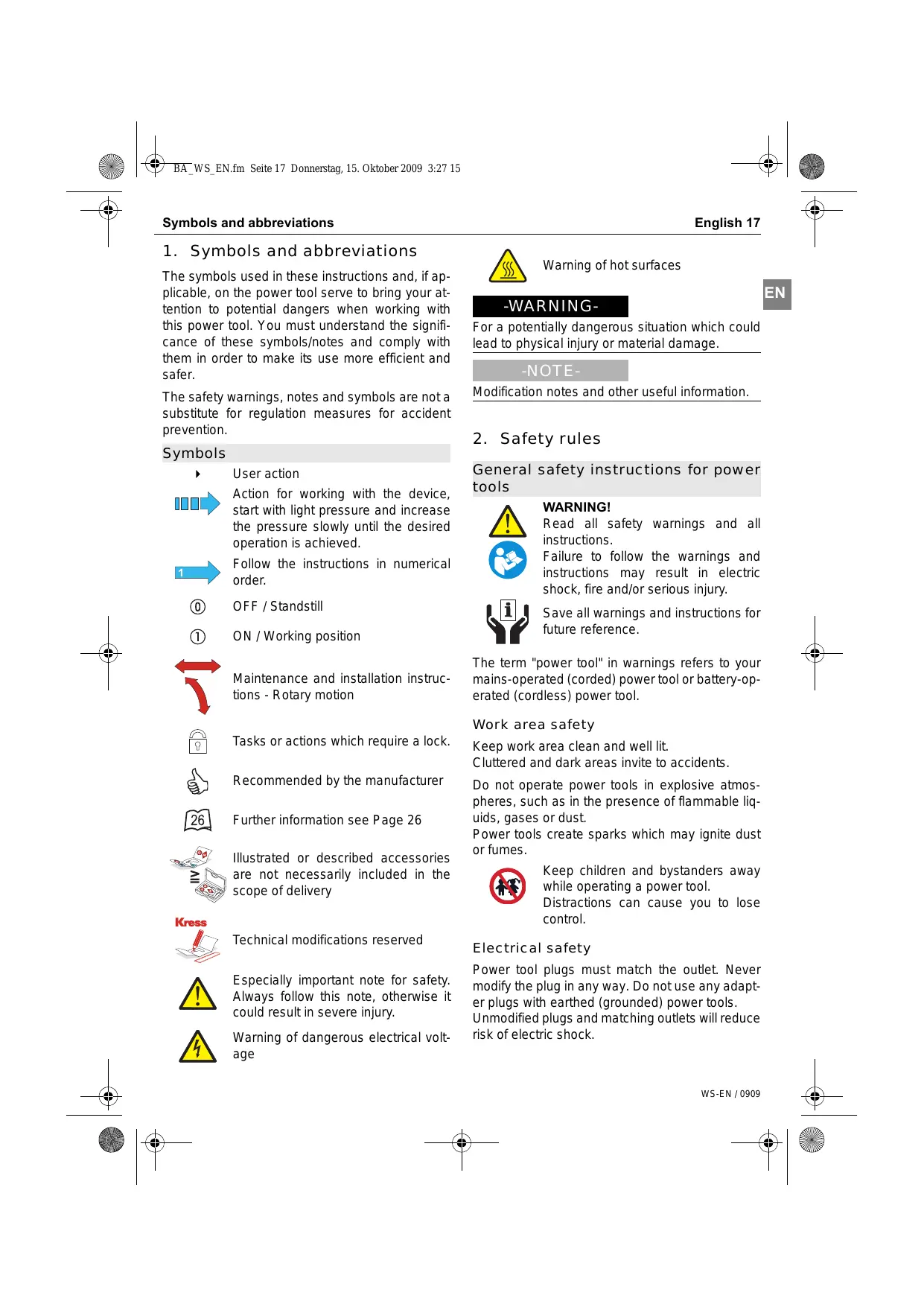
1. Symbols and abbreviations
The symbols used in these instructions and, if applicable, on the power tool serve to bring your attention to potential dangers when working with this power tool. You must understand the significance of these symbols/notes and comply with them in order to make its use more efficient and safer.
The safety warnings, notes and symbols are not a substitute for regulation measures for accident prevention.
Symbols
User action

Action for working with the device, start with light pressure and increase the pressure slowly until the desired operation is achieved.

Follow the instructions in numerical order.
OFF/Standstill
① ON / Working position

Maintenance and installation instructions - Rotary motion

Tasks or actions which require a lock.

Recommended by the manufacturer

Further information see Page 26

Illustrated or described accessories are not necessarily included in the scope of delivery

Technical modifications reserved

Especially important note for safety. Always follow this note, otherwise it could result in severe injury.

Warning of dangerous electrical voltage

Warning of hot surfaces
-WARNING-
For a potentially dangerous situation which could lead to physical injury or material damage.
-NOTE-
Modification notes and other useful information.
2. Safety rules
General safety instructions for power tools

WARNING!
Read all safety warnings and all instructions.

Failure to follow the warnings and instructions may result in electric shock, fire and/or serious injury.

Save all warnings and instructions for future reference.
The term "power tool" in warnings refers to your mains-operated (corded) power tool or battery-operated (cordless) power tool.
Work area safety
Keep work area clean and well lit.
Cluttered and dark areas invite to accidents.
Do not operate power tools in explosive atmospheres, such as in the presence of flammable liquids, gases or dust.
Power tools create sparks which may ignite dust or fumes.

Keep children and bystanders away while operating a power tool.
Distractions can cause you to lose control.
Electrical safety
Power tool plugs must match the outlet. Never modify the plug in any way. Do not use any adapter plugs with earthed (grounded) power tools.
Unmodified plugs and matching outlets will reduce risk of electric shock.
Avoid body contact with grounded surfaces such as pipes, radiators, ranges and refrigerators.
Do not expose power tools to rain or wet conditions.
Water entering a power tool will increase the risk of electric shock.
Do not abuse the cord. Never use the cord for carrying, pulling or unplugging the power tool. Keep cord away from heat, oil, sharp edges or moving parts.
Damaged or entangled cords increase the risk of electric shock.
When operating a power tool outdoors, use an extension cord suitable for outdoor use.
Use of a cord suitable for outdoor use reduces the risk of electric shock.
If operating a power tool in a damp location is unavoidable, use a residual current device (RCD) protected supply.
Use of an RCD reduces the risk of electric shock.
Personal safety
Stay alert, watch what you are doing and use common sense when operating a power tool. Do not use a power tool while you are tired or under the influence of drugs, alcohol or medication.
A moment of inattention while operating power tools may result in serious personal injury.

Use safety equipment. Always wear eye protection.
Safety equipment such as dust mask, non-skid safety shoes, hard hat, or hearing protection used for appropriate conditions will reduce personal injuries.

Prevent unintentional starting. Ensure the switch is in the off-position before connecting to power source and/or battery pack, picking up or carrying the tool.
Carrying power tools with your finger on the switch or energising power tools that have the switch on invites accidents.
Remove any adjusting key or wrench before turning the power tool on.
A wrench or a key left attached to a rotating part of the power tool may result in personal injury.
Do not overreach. Keep proper footing and balance at all times.
This enables better control of the power tool in unexpected situations.
Dress properly. Do not wear loose clothing or jewellery. Keep your hair, clothing and gloves away from moving parts.
Loose clothes, jewellery or long hair can be caught in moving parts.
If devices are provided for connecting dust extraction and collection facilities, ensure these are connected and properly used.
Use of these devices can reduce dust related hazards.
Power tool use and care
Do not force the power tool. Use the correct power tool for your application.
The correct power tool will do the job better and safer at the rate for which it was designed.
Do not use the power tool if the switch does not turn on and off.
Any power tool that cannot be controlled with the switch is dangerous and must be repaired.

Disconnect the plug from the power source and/or the battery pack from the power tool before making any adjustments, changing accessories, or storing power tools.
Such preventive safety measures reduce the risk of starting the power tool accidentally.
Store idle power tools out of the reach of children and do not allow persons unfamiliar with the power tool or these instructions to operate the power tool.
Power tools are dangerous in the hands of untrained users.
Maintain power tools. Check for misalignment or binding of moving parts, breakage of parts and any other condition that may affect the power tools operation. If damaged, have the power tool repaired before use.
Many accidents are caused by poorly maintained power tools.
Keep cutting tools sharp and clean.
Properly maintained cutting tools with sharp cutting edges are less likely to bind and are easier to control.
Use the power tool, accessories and tool bits etc. in accordance with these instructions and in the manner intended for the particular type of power tool, taking into account the working conditions and the work to be performed.
Use of the power tool for operations different from those intended could result in a hazardous situation.
Service

Have your power tool serviced by a qualified repair person using only original spare parts.
This will ensure that the safety of the power tool is maintained.
Machine-specific SafetyWarnings
Safety instructions for grinding, sanding with sanding discs, working with wire brushes and abrasive cutting-off operations
This Power tool is intended to function as a grinder, wire bruch, polisher or cut-off tool. Read all safety warnings, instructions, illustrations and specifications provided with this power tool.
Failure to follow all instructions listed below may result in electric shock, fire and/or serious injury.
This power tool is not recommended for polishing. Operations for which the power tool was not designed may create a hazard and cause personal injury.
Do not use accessories which are not specifically designed and recommended by the tool manufacturer.
Just because the accessory can be attached to your power tool, it does not assure safe operation.

The rated speed of the accessory must be at least equal to the maximum speed marked on the power tool.
Accessories running faster than their rated spees can break and fly apart.
The outside diameter and the thickness of your accessory must be within the capacity rating of your power tool.
Incorrectly sized accessories cannot be adequately guarded or controlled.

The arbour size of wheels, flanges, backing pads or any other accessory must properly fit the spindle of the power tool.
Accessories with arbour holes that do not match the mounting hardware of the power tool will run out of balance, vibrate excessively and may cause loss of control.


Do not use a damaged accessory. Before each use inspect the accessory such as abrasive wheels for chips and cracks, backing pad for cracks, tear or excess wear, wire brush for loose or cracked wires. If power tool or accessory is dropped, inspect for damage or install an undamaged accessory. After inspecting and installing an accessory, position yourself and bystanders away from the plane of the rotating accessory and run the power tool at maximum no-load speed for one minute.
Damaged accessories will normally break apart during this test time.


Wear personal protective equipment. Depending o application, use face shield, safety goggles or safety glasses. As appropriate, wear dust mask, hearing protectors, gloves and workshop apron capable of stopping small abrasive or workpiece fragments.
The eye protection must be capable of stopping flying debris generated by various operations. The dust mask or respirator must be capable of filtrating particles generated by your operation. Prolonged exposure to high intensity noise may cause hearing loss.

Keep bystanders a safe distance away from work area. Anyone entering the work area must wear personal protective equipment.
Fragments of workpiece or of a broken accessory may fly away and cause injury beyond immediate area of operation.
Hold power tool by insulated gripping surfaces only, when performing an operation where the cutting accessory may contact hidden wiring or its own cord.
Cutting accessory contacting a "live" wire may make exposed metal parts of the power tool "live" and shock the operator.
Position the cord clear of the spinning accessory. If you lose control, the cord may be cut or snagged and your hand or arm may be pulled into the spinning accessory.

Never lay the power tool down until the accessory has come to a complete stop.
The spinning accessory may grab the surface and pull the power tool out of your control.
Do not run the power tool while carrying it at your side.
Accidental contact with the spinning accessory could snag your clothing, fulling the accessory into your body.
Regularly clean the power tool's air vents.
The motor's fan will draw the dust inside the housing and excessive accumulation of powdered metal may cause electrical hazards.

Do not operate the power tool near flammable materials.
Sparks could ignite these materials.

Do not use accessories that require liquid coolants.
Using water or other liquid coolants may result in electrocution or shock.
Kickback and RelatedWarnings
Kickback is a sudden reaction to a pinched or snagged rotating wheel, backing pad, brush or any other accessory. Pinching or snagging causes rapid stalling of the rotating accessory which in turn causes the uncontrolled power tool to be
forced in the direction opposite of the accessory's rotation at the point of the binding.
For example, if an abrasive wheel is snagged or pinched by the workpiece, the edge of the wheel that is entering into the pinch point can dig into the surface of the material causing the wheel to climb out or kick out. The wheel may either jump toward or away from the operator, depending on direction of the wheel's movement at the point of pinching. Abrasive wheels may also break under these conditions.
Kickback is the result of power tool misuse and/or incorrect operating procedures or conditions and can be avoided by taking proper precautions as given below.
Maintain a firm grip on the power tool and position your body and arm to allow you to resist kickback forces. Always use auxiliary handle, if provided, for maximum control over kickback or torque reaction during start-up.
The operator can control torque or kickback forces, if proper precautions are taken.
Never place your hand near the rotating accessory. Accessory may kickback over your hand.
Do not position your body in the area where power tool will move if kickback occurs.
Kickback will propel the tool in direction opposite to the wheel's movement at the point of snagging.
Use special care when working corners, sharp edges etc. Avoid bouncing and snagging the accessory.
Corners, sharp edges or bouncing have a tendency to snag the rotating accessory and cause loss of control or kickback.

Do not attach a saw chain woodcarving blade or toothed saw blade.
Such blades create frequent kickback and loss of control.

SafetyWarnings Specific for Grinding and Abrasive Cutting-Off Operations
Use only wheel types that are recommended for your power tool and the specific guard designed for the selected wheel.
Wheels for which the power tool was not designed cannot be adequately guarded and are unsafe.

The guard must be securely attached to the power tool and positioned for maximum safety, so the least amount of wheel is exposed towards the operator.
The guard helps to protect operator from broken wheel fragments and accidental contact with wheel.
Wheels must be used only for recommended applications. For example: do not grind with the side of cut-off wheel.
Abrasive cut-off wheels are intended for peripheral grinding, side forces applied to these wheels may cause them to shatter.
Always use undamaged wheel flanges that are of correct size and shape for your selected wheel.
Proper wheel flanges support the wheel thus reducing the possibility of wheel breakage. Flanges for cut-off wheels may be different from grinding wheel flanges.
Do not use worn down wheels from larger power tools.
Wheel intended for larger power tool is not suitable for the higher speed of a smaller tool and may burst.
Additional safety instructions for abrasive cutting-off operations
Do not "jam" the cut-off wheel or apply excessive pressure. Do not attempt to make an excessive depth of cut.
Overstressing the wheel increases the loading and susceptibility to twisting or binding of the wheel in the cut and the possibility of kickback or wheel breakage.
Do not position your body in line with and behind the rotationg wheel.
When the wheel, at the point of operation, is moving away from your body, the possible kickback may propel the spinning wheel and the power tool directly at you.
When wheel is binding or when interrupting a cut for any reason, switch off the power tool and hold the power tool motionless until the wheel comes to a complete stop. Never attempt to remove the cutoff wheel from the cut while the wheel is in motion otherwise kickback may occur.
Investigate and take corrective action to eliminate the cause of wheel binding.
Do not restart the cutting operation in the workpiece. Let the wheel reach full speed and carefully reenter the cut.
The wheel may bind, walk up or kickback it the power tool is restarted in the workpiece.
Support panels or any oversized workpiece to minimize the risk of wheel pinching and kickback. Large workpieces tend to sag under their own weight. Support must be placed under the workpiece near the line of cut and near the edge of the workpiece on both sides of the wheel.
Use extra caution when making a "pocket cut" into existing walls or other blind areas.
The protruding wheel may cut gas or water pipes, electrical wiring or objects that can cause kickback.
Safety warnings specific for sanding operations
Do not use excessively oversized sanding disc paper. Follow manufacturers recommendations, when selecting sanding paper.
Larger sanding paper extending beyond the sand-ing pad presents a laceration hazard and may cause snagging, tearing of the disc, or kickback.
SafetyWarningspecificforWire Brushing Operations
Be aware that wire bristles are thrown by the brush even during ordinary operation. Do not overstress the wires by applying excessive load to the brush.
The wire bristles can easily penetrate light clothing and/or skin.
If the use of a guard is recommended for wire brushing, do not allow any interference of the wire wheel or brush with the guard.
Wire wheel or brush may expand in diameter due to work load and centrifugal forces.
Additional warnings

Wear protective glasses and hearing protection.

Use suitable detectors to determine if utility lines are hidden in the work area or call the local utility company for assistance.
Contact with electric lines can lead to fire and electric shock. Damaging a gas line can lead to
explosion. Penetrating a water line causes property damage or may cause an electric shock.
Always use the protective devices prescribed for the respective application.
Protective devices which are unsuitable for the application do not adequately guard the wheel.
During operation, always ensure that the mains and extension cable is to the rear away from the device.
This prevents anyone from tripping over the cable while working.
When working with the machine, always hold it firmly with both hands and provide for a secure stance.
The power tool is guided more secure with both hands.

Secure the workpiece.
A workpiece clamped with clamping devices or in a vice is held more secure than by hand.

Do not work on stone containing crystalline silica (SiO2).
This will produce dust which is dangerous to your health.

Do not work on materials containing asbestos.
Asbestos is considered carcinogenic!
Take protective measures if there is danger of formation of combustible or explosive dust during operation that can be hazardous to health.
Example: Some dusts can be carcinogenic. Wear a dust mask and work with a dust/chip extraction unit, if possible to connect.
Keep your workplace clean.
Blends of materials are particularly dangerous.
Dust from light alloys can burn or explode.
Do not clamp the machine into a vice.
A vice does not have suitable protective devices and thus causes an increased risk of injury.

Tools not in use must be locked away safely in a dry place out of the reach of children.

To mark the machine, do not drill into the housing.
The protective insulation would be bridged. Use stickers.

Never use the machine with a damaged cable. Do not touch the damaged cable and pull the mains plug when the cable gets damaged during operation.
Damaged cables increase the risk of electric shock.
Residual risk. Although this information sheet and the operating manuals for our electrical tools contain extensive instructions on safe working with electrical tools, every electrical tool involves certain residual risks that cannot be completely prevented through safety mechanisms. Therefore, electrical tools must always be operated with the necessary caution.
3. Device description

Read all the warnings and instructions before using the equipment. Failure to follow the warnings and instructions may result in electric shock, fire and/or serious injury.
For help, please use the enclosed illustrations showing the device. Open these illustrations while reading the operating instructions.
Operating elements
I Spindle stop button
II On/off switch
III Stop / unlocking switch (Option)
IV Adjuster for speed selection
V Clamping screw or clamping lever (Option)
VI Interlock button mains cable module (Option)
VII Handle unlocking button (Option)
Device components
1 Additional handle
2 Machine head
3 Motor housing
4 Bow-shaped handle (Option)
5 Protection guard for grinding
6 Protection guard for cutting (Accessory)
7 Auxiliary handle collar
8 Grinderspindle
9 Adjustment screw (Option)
10 Mains cable module / fixed supply
11 Clamping flange
12 Clamping nut
13 Quick-clamping nut Fixtec (Accessory)
14 Face spanner
15 Grinding disc (Accessory)
16 Cutting disc (Accessory)
17 Cup-shaped wire brush (Accessory)
18 Backing pad with sanding disc (Accessory)
Scope of supply
See packaging
Specified Conditions of Use
The machine is intended for cutting, roughing, and brushing metal and stone materials without using water.
For cutting metal, a special protection guard for cutting (accessory) must be used.
With approved sanding tools, the machine can be used for sanding with sanding discs.
Requirements for the user
The tool must only be operated, maintained and serviced by authorised trained personnel. The personnel must be made aware of the relevant dangers.
Technical data

Mains voltage in V / Frequency in Hz

Input power in Watts (W)

Output power in Watts (W)

Noise levels
K = Measurement uncertainty value The noise level can exceed 85 dB(A) during operation.
Wear hearing protection!

Triaxial vibration emission level determined in accordance with EN 60745.
K = Measurement uncertainty value

Roughing (surface grinding):
Vibration emission level a_h

Sanding with sanding discs:
Vibration emission level a_h

The vibration emission level given in this information sheet has been measured in accordance with a standardised test given in EN 60745 and may be used to compare one tool with another.
The vibration emission level will vary because of the ways in which a power tool can be used and may increase above the level given in this information sheet. This could lead to underestimation of vibration when the tool is used regularly in such a manner.
Note: To be accurate, an estimation of the level of exposure to vibration experienced during a given period of work should also take into account the times when the tool is switched off and when it is running but not actually when doing the job.
This may significantly reduce the exposure level over the total working period.
Identify additional safety measures to protect the operator from the effects of vibration such as: maintain the tool and accessories, keep the hands warm, organisation of work patterns.

n_0 = Idle speed in rpm
n_1 = Load speed in rpm

Grinding disc diameter, max.

Thread of grinder spindle

Clamping hole grinding disc

Restarting Protection

Reduced starting current

constant
Continuous electronic control

control
Speed selection

Weight in kg

Your power tool is double-insulated in accordance with EN 60745; For this reason an earth wire is not required.
The device is suppressed against radio and TV broadcasts, in accordance with EN 55014-1 and is immune to disturbances in accordance with EN 55014-2.
4. Operation

Before carrying out any work on the machine, pull the mains plug.
Putting into operation

Observe correct main voltage!
Before putting into operation, check that the mains voltage and frequency on the identification plate match the details of your mains supply.
Mounting the Protective Devices
Fit the additional handle
Connect mains cable module if necessary

If using an extension cable: Only use extension cables specifically approved for the application with the required cross-section. Otherwise the power of the tool can be reduced and the cable can overheat. Replace damaged cables.
Additional handle

Use auxiliary handles supplied with the tool.
Loss of control can cause personal injury.
Screw the auxiliary handle 1 on the machine head 2 depending on the working method.
Anti-vibration handle (Option)
The vibration-damping auxiliary handle 1 ensures low-vibration, more comfortable and safe working.
Do not modify the auxiliary handle in any way.
Never use a damaged auxiliary handle.
Mains cable

If the mains cable is damaged while working, pull the mains plug immediately.
Fixed power supply

Fixed power supply
Damaged mains cables must not be used. They must be replaced immediately by an expert technician.
Mains cable module

Mains cable module with Patent Quick Interlock.
Connect the mains cable module 10 to the handle. The plug must snap in.
Use the mains cable module 10 only for Kress electric tools. Do not attempt to operate other machines with the module.
Damaged mains cable modules must not be used. They must be replaced by a new Kress mains cable module immediately.
- Push the two unlocking buttons VI and remove the mains cable module 10 from the handle.
Use only an original Kress mains cable module and at least a heavy rubber tube cable (H07RN-F).
Additional functions (Option)
Reduced starting current (Option)
The electronic reduced starting current limits the power consumption when switching the tool on and enables operation from a 13 ampere fuse.
-NOTE-
A machine without reduced starting current requires higher fuse protection (use at least a 13 A time-delay fuse).
Restart protection (Option)

The restart protection prevents the device starting up again in an uncontrolled manner when the power supply comes back on after an interruption.
Resuming operation: Turn the On/Off switch II to Off position and switch the device on again.
Continuous electronic control (Option)

constant
The continuous electronic control keeps the speed almost constant under no-load and under load and ensures uniform performance.
Electronic control (Option)

In the event of overload or overheating during continuous operation, the speed is automatically reduced until the machine has cooled sufficiently.
Mounting the Protective Devices

Before carrying out any work on the machine, pull the mains plug.

When working with roughing or cutting discs, the appropriate protective cover must be mounted.
Roughing/grinding with protective cover for grinding 5.
Cutting with protective cover for cutting 6.
Adjust the position of the protection guard to the requirements of the work process.
-WARNING
Adjust the protection guard in such a manner that sparking is prevented in the direction of the operator.
Depending on the specific configuration, protective cover 5/6 may be equipped with various attachment fittings.

Protective cover with clamping screw, can only be adjusted with a tool.

Protective cover with quick clamp, can be adjusted without the use of tools.

Protective cover with lock, can be adjusted without the use of tools.
Protective cover with clamping screw
Loosen the clamping screw V
Insert protective cover 5/6 with the cam into the groove on auxiliary handle collar 7 of machine head 2 and turn to the required position (working position).
- Tighten clamping screw V.
Protection Guard with Quick Clamp
Open the clamping lever V.
Insert protective cover 5/6 with the cam into the groove on auxiliary handle collar 7 of machine head 2 and turn to the required position (working position).
To fasten the protection guard, close the clamping lever V
-NOTE-
The protection guard 5/6 is preadjusted to the diameter of the spindle collar 7. If required, the tightening tension of the clamping bracket can be changed by tightening or loosening the adjustment screw 9. Always ensure that the protection guard 5/6 is seated tightly on the spindle collar.
Protective cover with lock
Depending on the application, adjust protective cover 5/6 as far as the stop without tools.
Operation

After switching off, the grinding tool runs on for a short time.
If there is contact between the tool and the support surface, there is a danger of losing control of the machine.
On-/Off

Check grinding tools before using. The grinding tool must be mounted properly and be able to move freely. Carry out a test run for at least one minute with no load. Do not use damaged, out-of-centre or vibrating grinding tools.
Damaged grinding tools can burst and cause injuries.
One-hand angle grinder (up to 1500W)
Brief operation without locking:
Push On/Off switch II forwards and hold in this position.
To switch off, release On/Off switch II.
Continuous operation with locking:
Push On/Off switch II forwards and engage it in this position by exerting pressure on the front end.
To switch the machine off, unlock On/Off switch II by exerting pressure on the tilted front edge.
Two-hand angle grinder (from 1600 W)
Continuous operation with locking:
Press unlocking switch III and hold it in this position.
Press On/Off switch II and hold it in this position.
Press locking switch III.
To switch off, briefly press On/Off switch II and then release it.
-WARNING-
Machines without restart protection will start up again if switched on.

Switch design without lock (country-specific) or brief operation:
Press unlocking switch III and hold it in this position.
Press On/Off switch II and hold it in this position.
To switch off, release On/Off switch II.
Preselect speed (Option)
Speed selector thumb wheel IV allows you to preselect the required speed even during operation.
Mounting the Grinding Tools

Disconnect the plug from the power source before making any adjustments, changing accessories, or storing power tools.
Such preventive safety measures prevent accidental start of the power tool.

Wear safety gloves for tool changing.
The tool insert can become very hot after working for long periods and/or the cutting edges of the tool insert are sharp.
-WARNING-
Observe the tool-specific information in Chapter 5.
Locking the grinder spindle
The grinder spindle must be locked in position in order to change tools.
To lock the grinder spindle, press spindle stop button I and hold it pressed.
If it is not possible to depress the spindle stop button all the way, rotate the grinder spindle clockwise until it engages.
-NOTE-
Actuate the spindle lock button only when the grinder spindle is at a standstill. Otherwise, the machine may become damaged.
Mounting the Grinding Tool

Do not use a damaged accessory.
They may break, thus increasing the risk of injury.
Clean the grinder spindle 8 and all parts to be mounted.
Insert tool 15/16 in the correct position. The correct sequence for mounting is shown in the illustrated instructions "Mounting the grinding tools."
Screw clamping nut 12 onto grinder spindle 8 in the correct position.
Press spindle stop button I and hold it pressed.
- Tighten clamping nut 12 with face spanner 14.
-NOTE-
Before switching the machine on after mounting the grinding tool, check that the grinding tool is correctly mounted and can rotate freely. Make sure that the grinding tool does not brush against the protective cover or other parts.
Removing grinding tools
Press spindle stop button I and hold it pressed.
- Release and remove clamping nut 12 from spindle 8 by turning the nut anti-clockwise using face spanner 14.
Remove tools and clamping flange 11 from spindle 8.
Mounting a cup-shaped wire brush
Clean grinder spindle 8.
Screw cup-shaped wire brush 17 directly onto grinder spindle 8 without using clamping flange 11 and clamping nut 12.
Press spindle stop button I and hold it pressed.
- Tighten cup-shaped wire brush 17 with an open-ended wrench.
Removing the cup-shaped wire brush
Press spindle stop button I and hold it pressed.
Release cup-shaped wire brush 17 with an open-ended wrench.
Operating tips

Clamp the workpiece if it does not remain stationary due to its own weight.

Grinding and cutting discs become very hot while working; do not touch until they have cooled.

Wear protective glasses and hearing protection.
Do not strain the machine so heavily that it comes to a standstill.
Rough Grinding


The best roughing results are achieved when setting the machine at an angle of 30^ to 40^ .
-WARNING-
Never use a cutting disc for roughing.
Move the machine back and forth with moderate pressure. In this manner, the workpiece will not become too hot, does not discolour and no grooves are formed.
Abrasive cutting-off operations

For cutting, always work with the protection guard for cutting 6.

Do not exert pressure onto the cutting disc, tilt or oscillate the machine.

Always work in reverse rotation with the angle grinder
There is a danger of the grinder jumping out of the cut in an uncontrolled manner.
When cutting, work with moderate feed, adapted to the material being cut. Rule of thumb: the harder the material, the slower the speed.
Do not reduce the speed of running down cutting discs by applying sideward pressure.
Cutting Metall
For cutting metal, always work with the protection guard for cutting 6.
Cutting Stone

The machine may be used only for dry cutting/ grinding.
For cutting stone, it is best to use a diamond cutting disc.
Working with a diamond cutting disc
For cutting especially hard material, e. g., concrete with high pebble content, the diamond cutting disc can overheat and become damaged as a result. This is clearly indicated by circular sparking, rotating with the diamond cutting disc.
In this case, interrupt the cutting process and allow the diamond cutting disc to cool by running the machine for a short time at maximum speed with no load.
Noticeable decreasing work progress and circular sparking are indications of a diamond cutting disc that has become dull. Briefly cutting into abrasive material (e.g. lime-sand brick) can resharpen the disc again.
Working with a cup-shaped wire brush

Use the cup-shaped wire brush to derust and clean metal and stone and to prepare surfaces for soldering and welding work.
Avoid motor overload
If the motor housing of the angle grinder becomes hot, the load on the motor is too high (danger of the motor burning).
Operate the machine at no-load speed to allow the motor to cool.
Turning the machine handle (Option)

Before carrying out any work on the machine, pull the mains plug.
Bow-shaped handle 4 can be rotated 90^ to the left and to the right in the direction of motor housing 3. This allows you to position On/Off switch II more conveniently for special working conditions; e. g. for abrasive cutting-off operations or for left-handed people.
Press handle unlocking device VII at at the same time, rotate bow-shaped handle 4 to the desired position until it engages.
-WARNING
Do not use the tool unless the rotatable handle is secured.
5. Tools and accessories
Use only tools and accessories recommended for use with the KRESS machine described in the illustrated instructions.

Do not attach a saw chain woodcarving blade or toothed saw blade.
Such blades create frequent kickback and loss of control over the power tool.
Approved Grinding Tools
All grinding tools mentioned in these operating instructions can be used.
Observe the permissible rotational/ circumferential speed on the label of the grinding tool.
The values shown on the type plate of the angle grinder must not exceed the permissible speed [rpm] or circumferential speed [m / s] of the grinding tools used.
For safety reasons, the grinding tools must not be operated at circumferential speeds exceeding 80 m/s.
Observe the dimensions of the grinding tools. The diameter of the hole must fit clamping flange 11. Do not use adapters or reducers.
When using grinding tools, always observe the information provided by the grinding tool manufacturer.
Roughening/cutting disc
Observe the manufacturer's instructions!
Diamond cutting disc
When using diamond cutting discs, pay attention that the direction-of-rotation arrow on the diamond cutting disc and the direction of rotation of the machine (see direction-of-rotation arrow on the machine head) agree.
Flap Disc
With the flap disc (accessory), curved surfaces and profiles can be worked.
Flap discs have a considerably higher service life, lower noise levels and lower sanding temperatures than conventional sanding sheets.
Cup-shaped wire brush
Observe the maximum permissible speed of the cup-shaped wire brush in relation to the speed of your angle grinder.
Observe the manufacturer's instructions!
Backing pads for sanding with sanding discs
Observe the manufacturer's instructions!
Safety devices
Protective cover for roughening work 5
Protective cover for abrasive cutting work 6
Accessories
Additional handle 1
Face spanner 14
Clamping flange 11
Clamping nut 12
Quick-clamping nut Fixtec 13
Quick-clamping nut Fixtec
For convenient changing of grinding tools without the use of additional tools, you can use the quick-clamping nut 13 instead of the clamping nut 12.
-NOTE-
The quick-clamping nut 13 may be used only for grinding or cutting discs (One-hand angle grinder).
6. Maintenance and Service
Maintenance and Cleaning

Before carrying out any work on the machine, pull the mains plug.
Always keep the machine and ventilation slots clean.
Wipe off the accessible plastic parts regularly with a cloth without cleaning agent.
-NOTE-
In extreme working conditions, conductive dust can accumulate in the interior of the machine when working with metal. The protective insulation of the machine can be degraded. The use of a stationary extraction system is recommended in such cases as well as frequently blowing out the ventilation slots and installing a residual current device (RCD).
Replacing brushes
The angle grinder is equipped with cut-off carbon brushes.
The angle grinder is switched off automatically when the wear limit for the cut-off carbon brushes is reached.
Worn carbon brushes should be replaced by an authorised customer service organisation.
Service

After heavy use over a long period, the machine should be taken to a Kress service location for inspection and thorough cleaning.
The relevant service centres are listed in the enclosed appendix "SERVICE" or on the website www.kress-elektrik.de.
Spare parts / exploded view
Exploded views and spare parts lists are available on our home-page
http://spareparts.kress-elektrik.de
Environmental Protection

Recycle raw materials instead of disposing them as waste. The machine, accessories and packaging should be sorted for environmental-friendly recycling.
The plastic components are labelled for categorised recycling.

Only for EC countries.
Do not dispose of electric tools together with household waste material!
In observance of the European Directive 2002/96/EC for waste electrical and electronic equipment and its implementation in accordance with national law,
electric tools that have reached the end of their life must be collected separately and returned to an environmentally compatible recycling facility.
Warranty
- This power tool has been carefully tested and has been subjected to a strict quality control process.
- We guarantee the free-of-charge repair of faults in the power tool that arise within 24 months from the date of purchase at the end user's premises and which can be attributed to a material or manufacturing defect. In certain countries there are special regulations concerning the warranty terms. We reserve the right to repair faulty components or to replace them. Replaced items become our property.
- Inappropriate use or handling and opening up the device by unauthorised repair centres leads to the warranty becoming void. The warranty does not cover: mechanical damage due to falls etc., damage caused by penetration of water or other fluids, cut and damaged cables, motor damage and mechanical damage caused by inappropriate overloading, wear parts e.g. carbon brushes, drill chucks, chuck keys, worn drilling spindles, motors, mains cables, batteries, saw blades, grinding discs, dust bags, accessories in general (drill bits, chisels etc.). Details of the various toll wear parts can be obtained from http:// spareparts.kress-elektrik.de or from one of our service centres.
- The warranty may only be enforced when defects are reported without undue delay (including shipping damage). Warranty implementation does not extend the warranty period.
- If you need to apply the warranty, send the original purchase receipt together with the device to us or to the relevant service centre.
- The warranty obligations assumed by us shall exclude any further claims on the part of the buyer, in particular the right to cancellation of a sale, reduction and the assertion of damage claims.
- However, the buyer shall have the right to either a reduction (in the purchase price) or the cancellation of the sales agreement should we fail to eliminate any defects within a reasonable period of time.
- This does not exclude compensation claims in accordance with §§ 463, 480 Para. 2, 635 BGB caused by the failure of assured properties.
- The provisions defined in Items 7 and 8 only apply to the Federal Republic of Germany.