
MagicWatch MWE 7106F - Refrigerator DOMETIC - Free user manual and instructions
Find the device manual for free MagicWatch MWE 7106F DOMETIC in PDF.


| Product type | Motorhome refrigerator |
| Brand | Dometic |
| Model | MagicWatch MWE 7106F |
| Net capacity | 106 liters |
| Dimensions (H x W x D) | 850 x 525 x 550 mm |
| Weight | 18 kg |
| Power supply | 12 V DC / 230 V AC (adaptable) |
| Energy consumption | Approximately 45 W at 12 V |
| Climate class | N (temperate) |
| Main functions | Refrigeration and freezing (freezer compartment); adjustable thermostat |
| Defrost type | Manual |
| Refrigerant | R600a (isobutane) |
| Noise level | ≤ 40 dB(A) |
| Maintenance and cleaning | Clean the interior with a damp cloth and mild detergent; defrost regularly; check door seals |
| Safety | Low voltage operation with reverse polarity protection; automatic shut-off in case of overheating |
| Spare parts and repairability | Parts available from Dometic after-sales service; repair possible by an authorized professional |
| General information | Suitable for use in motorhomes, caravans and boats; built-in or free-standing installation |
Frequently Asked Questions - MagicWatch MWE 7106F DOMETIC
User questions about MagicWatch MWE 7106F DOMETIC
0 question about this device. Answer the ones you know or ask your own.
Ask a new question about this device
Download the instructions for your Refrigerator in PDF format for free! Find your manual MagicWatch MWE 7106F - DOMETIC and take your electronic device back in hand. On this page are published all the documents necessary for the use of your device. MagicWatch MWE 7106F by DOMETIC.
USER MANUAL MagicWatch MWE 7106F DOMETIC

DE: 16
ES: 76
DA: 136
FI: 196
PL: 256
HU: 316
EN: 36
IT: 96
SV: 156
PT: 216
CS: 276
FR: 56
NL: 116
NO: 176
RU: 236
SK: 296
15![graph TD A["01: >5s"] --> B["04: <1s"] B --> C["07: <1s"] C --> D["60: >2s"] D --> E["70: <1s"] E --> F["70: >2s"] F --> G["70: >10s"] G --> H["70: >5s"] I["DE: 16 NO: 176 EN: 36 FI: 196 FR: 56 PT: 216 ES: 76 RU: 236 IT: 96 PL: 256 NL: 116 CS: 276 DA: 136 SK: 296 SV: 156 HU: 316"] --> J["Display Pan…](/content/2026/07/1455023/images/dfd57337fd7d0858324da77e4973656bd1a91ebaebfe2b1f56af15b73232402e.jpg)


DE: 16 ES: 76 DA: 136 FI: 196 PL: 256 HU: 316
EN: 36 IT: 96 SV: 156 PT: 216 CS: 276
FR: 56 NL: 116 NO: 176 RU: 236 SK: 296
| 01 | 0 1 2 | 2 | |
| 03 | 0,2,3,4,6 | 6 | |
| 07 | 00 02,050,2,5s 5s | 5 | |
| 08 | 1 ... 991/s - 99/s 3/s | 3 | |
| 09 | 0 ... 90,0 - 0,9 0,0 | 0 | |
| 12 | 00 ... 10 | 00 | |
| 14 | 0 ... 1L R RL | 0 | |
| 21 | -9 ... +9 | 0 | |
| 22 | -9 ... +9 | 0 | |
| 23 | -9 ... +9 | 0 | |
| 24 | 45 ... 1245 – 120 cm 85 cm | 85 | |
| 25 | 45 ... 1245 – 120 cm | 6060 cm | |
| 26 | 45 ... 1245 – 120 cm 45 cm | 45 |
Min ... Max FactoryMin ... Max Facto
| 27 | 30 ... 5030 – 50 cm 35 cm | 35 | |
| 28 | 30 ... 5030 – 120 cm 35 cm | 35 | |
| 29 | 30 ... 5030 – 120 cm 30 cm | 30 | |
| 31 | 00,10,300, | 00 | |
| 32 | 00,10,300, | 00 | |
| 33 | 00,10,300, | 00 | |
| 35 | 0 10 ... 600 , 10 – 60 s 0 s | 0 | |
| 36 | 00 ... 01 | 00 | |
| 39 | 00 ... 01 | 01 | |
| 59 | 0 ... 1AUTO | 0 |

Programming instructions • Programming instructions • Programming instructions • Programming instructions • Programming instructions • Programming instructions • Programming instructions • Programming instructions • Programming instructions • Programming instructions • Programming instructions • Programming instructions • Programming instructions • Programming instructions • Programming instructions • Programming instructions
13
DE: 14
ES: 75
DA: 135
FI: 195
PL: 255
HU: 315
EN: 35
IT: 95
SV: 155
PT: 215
CS: 275
FR: 55
NL: 115
NO: 175
RU: 235
SK: 295
14

DE: 16
ES: 76
DA: 136
FI: 196
PL: 256
HU: 316
EN: 36
IT: 96
SV: 156
PT: 216
CS: 276
FR: 56
NL: 116
NO: 176
RU: 236
SK: 296
15![graph TD A["01: >5s"] --> B["04: <1s"] B --> C["07: <1s"] C --> D["60: >2s"] D --> E["70: <1s"] E --> F["70: >2s"] F --> G["70: >10s"] G --> H["70: >5s"] I["DE: 16 NO: 176 EN: 36 FI: 196 FR: 56 PT: 216 ES: 76 RU: 236 IT: 96 PL: 256 NL: 116 CS: 276 DA: 136 SK: 296 SV: 156 HU: 316"] --> J["Display Pan…](/content/2026/07/1455023/images/8e7e5969f8ba9a5a394cfee026fe4d37161480691006065817ef190ec50b0269.jpg)


DE: 16 ES: 76 DA: 136 FI: 196 PL: 256 HU: 316
EN: 36 IT: 96 SV: 156 PT: 216 CS: 276
FR: 56 NL: 116 NO: 176 RU: 236 SK: 296


Min ... Max FactoryMin ... Max Fact
1


DE: 6 NO: 167
EN: 27 FI: 187
FR: 47 PT: 207
ES: 67 RU: 227
IT: 87 PI: 247
NI: 107 CS: 267
NE: 187 DA: 127 SK: 287
DA: 127 OK: 207 SV: 147 HU: 207
6x


6x
2
DE: 8 NO: 169 EN: 29 FI: 189 FR: 49 PT: 209 ES: 69 RU: 229 IT: 89 PL: 249 NL: 109 CS: 249 DA: 129 SK: 289 SV: 149 HU: 309

DE: 8 ES: 69 DA: 129 FI: 189 PL: 249 HU: 309 EN: 29 IT: 89 SV: 149 PT: 209 CS: 269 FR: 49 NL: 109 NO: 169 RU: 229 SK: 289

DE: 9 ES: 70 DA: 130 FI: 190 PL: 250 HU: 310 EN: 30 IT: 90 SV: 150 PT: 210 CS: 270 FR: 50 NL: 110 NO: 170 RU: 230 SK: 290

5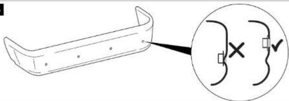


MWE7106
10 cm < 30 cm 25 - 30 cm 25 - 30 cm <
B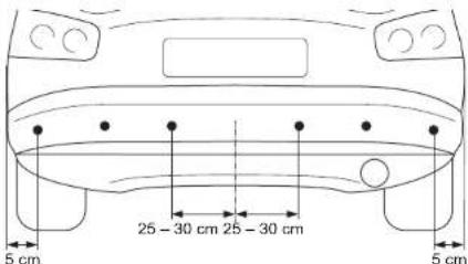
MWE7106F
B
7
8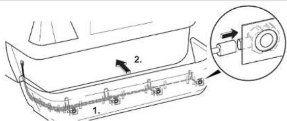
9
10 MWE7106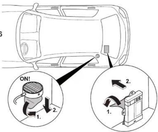
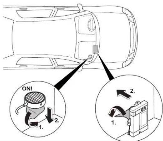
11
| DE: 11 | ES: 72 | DA: 132 | FI: 192 | PL: 252 | HU: 312 |
| EN: 32 | IT: 92 | SV: 152 | PT: 212 | CS: 272 | |
| FR: 52 | NL: 112 | NO: 172 | RU: 232 | SK: 292 |
MWE7106
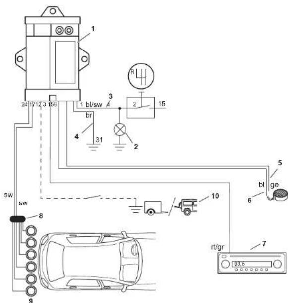
12
| DE: 13 | ES: 74 | DA: 134 | FI: 194 | PL: 254 | HU: 314 |
| EN: 34 | IT: 94 | SV: 154 | PT: 214 | CS: 274 | |
| FR: 54 | NL: 114 | NO: 174 | RU: 234 | SK: 294 |
MWE7106F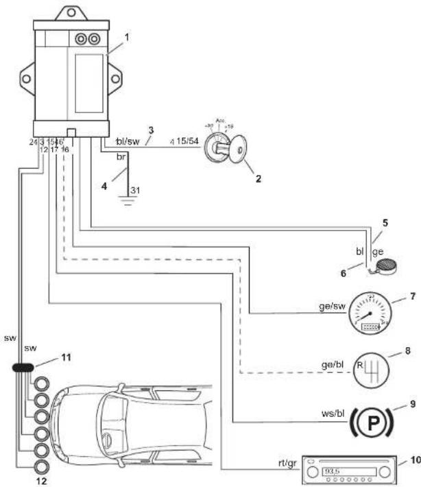
13
| DE: 13 | ES: 74 | DA: 134 | FI: 194 | PL: 254 | HU: 314 |
| EN: 34 | IT: 94 | SV: 154 | PT: 214 | CS: 274 | |
| FR: 54 | NL: 114 | NO: 174 | RU: 234 | SK: 294 |
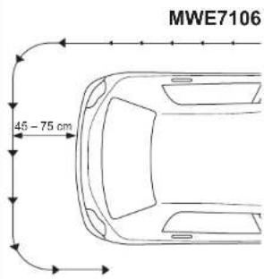
| EN | DE | FR | ES | IT | NL | DA | SV | |
| bl | Blue | Blau | Bleu | Azul | Blu | Blauw | Blà | Blà |
| br | Brown | Braun | Marron | Marrón | Marrone | Bruin | Brun | Brun |
| ge | Yellow | Gelb | Jaune | Amarillo | Giallo | Geel | Gul | Gul |
| gr | Grey | Grau | Gris | Gris | Grigio | Grijs | Grá | Grá |
| rt | Red | Rot | Rouge | Rojo | Rosso | Rood | Rød | Röd |
| sw | Black | Schwarz | Noir | Negro | Nero | Zwart | Sort | Svart |
| ws | Weiß | White | Blanc | Blanco | Bianco | Wit | Hvid | Vit |
| NO | FI | PT | RU | PL | CS | SK | HU | |
| bl | Blá | Sininen | Azul | Синий | Niebieski | Modrá | Modrá | Kék |
| br | Brun | Ruskea | Castanho | Коричневый | Brazowy | Hněda | Hnedá | Barna |
| ge | Gul | Keltainen | Amarelo | Желтый | Žolty | Žlutá | Žtta | Sarga |
| gr | Grá | Harmaa | Cinzento | Зеленый | Zielony | Zelená | Zelená | Szürke |
| rt | Rød | Punainen | Vermelho | Красный | Czerwony | Červená | Červená | Piros |
| sw | Svart | Musta | Preto | Черный | Czarny | Černá | Čierna | Fekete |
| ws | Hvit | Valkoinen | Branco | Белый | Biały | Bílá | Biela | Fehér |
WAECO
by Dometic GROUP
Dometic WAECO International GmbH
Hollefeldstrasse 63
D-48282 Emsdetten
www.dometic.com
MagicWatch
MWE7106, MWE7106F
DE 3 Parking aid
Installation and Operating Manual
Supplement to Fig. 8

Please read this instruction manual carefully before installation and first use, and store it in a safe place. If you pass on the product to another person, hand over this instruction manual along with it.
Table of contents
1 Explanation of symbols 25 2 Safety and installation instructions 25 3 Scope of delivery 27 4 Intended use 29 5 Instructions before installation 29 6 Fitting the parking aid 31 7 Connecting the parking aid 32 8 Registering and identifying sensors 34 9 Detection range 35 10 Setting the system 36 11 Performing a functional test 38 12 Using the parking aid 39 13 Troubleshooting 40 14 Warranty 42 15 Disposal 42 16 Technical data 43
1 Explanation of symbols

WARNING!
Safety instruction: Failure to observe this instruction can cause fatal or serious injury.

NOTICE!
Failure to observe this instruction can cause material damage and impair the function of the product.

NOTE
Supplementary information for operating the product.
▶ Action: This symbol indicates that action is required on your part. The required action is described step-by-step. √ This symbol describes the result of an action.
Fig. 1 5, page 3: This refers to an element in an illustration. In this case, item 5 in figure 1 on page 3.
2 Safety and installation instructions
The following texts are only a supplement to the illustrations on the supplementary sheet. They do not contain the full installation and operating instructions. Please observe the illustrations on the supplementary sheet.
Please observe the prescribed safety instructions and stipulations from the vehicle manufacturer and service workshops.
Observe the applicable legal regulations.
The manufacturer accepts no liability for damage in the following cases:
● Damage to the product resulting from mechanical influences and excess voltage - Alterations to the product without express permission from the manufacturer ● Use for purposes other than those described in the operating manual

WARNING!
- Secure the parts of the parking aid which are installed in the vehicle in such a way that they cannot become loose under any circumstances (sudden braking, accidents) and cause injuries to the occupants of the vehicle.
- Do not install the parts of the parking aid anywhere in the vehicle where an airbag may open. This could cause injury if the airbag deploys.
- The parking aid is intended as an additional aid, which means it does not relieve you of the obligation to take due care when manoeuvring.

NOTICE!
- Installing the parking aid can cause problems on vehicles with LED tail lights.
- If you would like to install the sensors on metal bumpers, you will require suitable adapters (not included in the scope of delivery).
- Do not expose the control electronics to dampness.
- Do not install the control electronics near any other control modules. ● The sensors may not cover signal lamps.
- When fitting the sensors, make sure there are no objects fixed to the vehicle (such as a bicycle rack, number plates) that are in the detection range of the sensors.
3 Scope of delivery
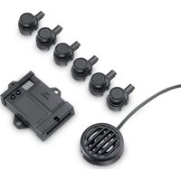
3.1 MWE7106
See fig. 1
| No. Quantity Description Item no. |
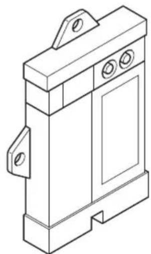
| 1 1 Control electronics 9101500074 |
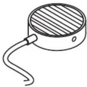
| 2 1 Loudspeaker MWD-900 |
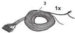
| 3 1 Control electronics connection cable |
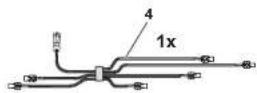
| 4 1 Sensor distributor 9101500067 |
| 5 6 Digital ultrasonic sensors (black) 9101500068 |
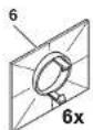
| 6 6 Standard 0° sensor holder(fitted from the inside) |
| 7 6 Standard 10° sensor holder(fitted from the inside) |
| 8 6 0° sensor holder with cover ring(fitted from the outside) |
| 9 6 12° sensor holder with cover ring(fitted from the outside) |
| 10 — Fastening material |
3.2 MWE7106F
See fig. 1
| No. Quantity Description Item no. |
| 1 1 Control electronics 9101500075 |
| 2 1 Loudspeaker MWD-900 |
| 3 1 Control electronics connection cable |
| 4 1 Sensor distributor 9101500067 |
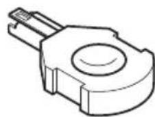
| 5 6 Digital ultrasonic sensors (black) 9101500068 |
| 6 6 Standard 0° sensor holder(fitted from the inside) |
| 7 6 Standard 10° sensor holder(fitted from the inside) |
| 8 — — |
| 9 6 12° sensor holder with cover ring(fitted from the outside) |
| 10 — Fastening material |
3.3 Accessories
Available as accessories (not included in the scope of delivery):
| Description | Item no. |
| Sensor holder for metal bumper | 9101500015 |
| Sensor extension cable, 1.5 m | 9103555747 |
| LED display | 9101500079 |
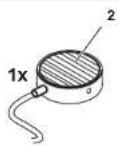
| External button MWE7106F | 9101500066 |
4 Intended use
MWE7106(F) is a parking aid based on ultrasound. It monitors space when manoeuvring
● MWE7106: rear area of the vehicle ● MWE7106F: front area of the vehicle
It provides an audible warning signal for any obstacles it detects.
MWE7106 is designed for installation in cars and vans.
5 Instructions before installation
5.1 Painting the sensors
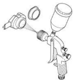
See fig. 2

NOTE
The sensors may be painted. The manufacturer recommends having the sensors painted by a specialist workshop.
5.2 Determining the place of installation for the sensors
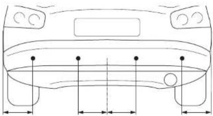
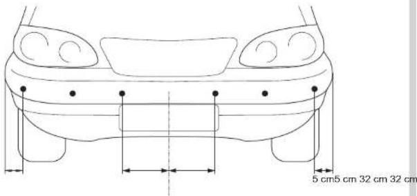
See fig. 3 to fig. 6

NOTE
The sensors must be correctly aligned for the device to work properly.
If they point to the ground, irregularities and bumps on the surface may be interpreted as obstacles. If they point too far up, obstacles will not be detected at all.
Note the following during installation:
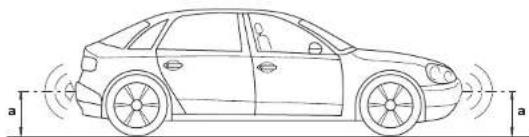
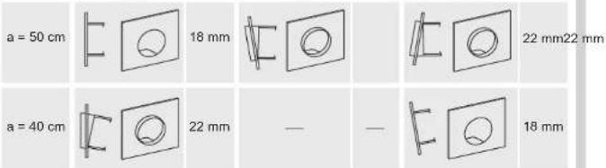
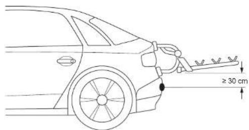
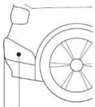
● The area around the sensors must be free from other objects. - The distance from the sensors to the ground should be at least 40 cm and a maximum of 50 cm (fig. 3). - Note that the installation angle depends on the installation height. Select the right sensor holder and the appropriate drill diameter by consulting the table in fig. 3. - MWE7106: If a bicycle rack has been fitted, then, taking the minimum installation into account, install the sensors at least 30 cm below it (fig. 4).
Supplementary to fig. 6
▶ Observe the intervals between sensors.

NOTE
You can also distribute the sensors as shown in alternative B.
6 Fitting the parking aid
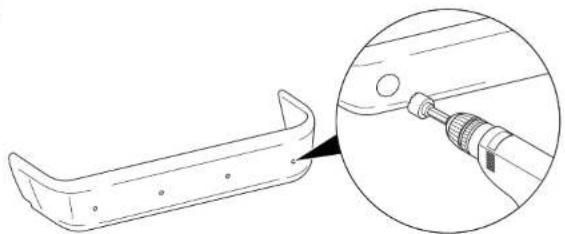
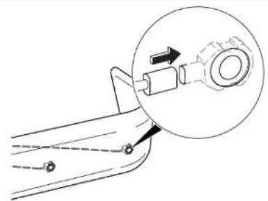
See fig. 7 to fig. 10
Supplement fig. 7

Supplementary to fig. 8

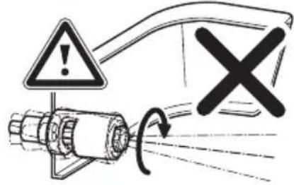
NOTICE! Risk of malfunction!
Align the sensor holders so that the fastening lugs are horizontal (fig. 3). Otherwise there is no guarantee the parking aid will function correctly.

NOTE
We recommend use of the punching tool for optimal installation device.
Push the sensor holders (fig. 1 8 or 9) into the holes (24 mm) until they lock into place.
7 Connecting the parking aid
MWE7106: See fig. 11

NOTE
On some vehicles, the reversing light only works when the ignition is switched on. In this case, you must switch on the ignition in order to identify the positive and earth wires.
| No. Description | Plug socket for plug |
| 1 Control electronics – | |
| 2 Reversing light – | |
| 3 Blue/black cable: connection to the reversing light 14 | |
| 4 Brown cable: Connection to earth 2 | |
| 5 Yellow wire from the loudspeaker 15 | |
| 6 Blue wire from the loudspeaker 3 | |
| 7 Red/grey cable: connection to the radio's mute connection (optional) | 6 |
| 8 Sensor connection cables (LIN bus) 12/24 | |
| (9/21) | |
| (10/22) | |
| (11/23) | |
| 9 Sensors – | |
| 10 Earth signal for bicycle trailer and trailer detection (see chapter “Setting the system” on page 36) | 17 |
MWE7106F: See fig. 12
| No. Description | Plug socket for plug |
| 1 Control electronics – | |
| 2 Ignition – | |
| 3 Blue/black cable: connection to ignition 14 | |
| 4 Brown cable: connection to earth 2 | |
| 5 Yellow wire from the loudspeaker 15 | |
| 6 Blue wire from the loudspeaker 3 | |
| 7 Yellow/black cable: connection to the speed signal from the speedometer (optional) | 16 |
| 8 Yellow/blue cable: connection to reversing light (optional) 4 | |
| 9 White/blue cable: connection to parking brake (optional) 17 | |
| 10 Red/grey cable: connection to the radio's mute connection (optional) | 6 |
| 11 Sensor connection cables (LIN bus) | 12/24(9/21)(10/22)(11/23) |
| 12 Sensors | – |
8 Registering and identifying sensors
The sensors and their position must be registered by the control unit. To do this, proceed as follows:
Switch on the ignition. Engage the reverse gear. The control unit registers the sensors connected.
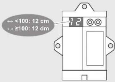
The display on the control unit shows LE.
The loudspeaker emits short acoustic signals repeatedly.
Once the registration is complete, LE flashes on the display. The sensors must now be identified by the control unit.
Park the vehicle so that it is surrounded by at least 1 m of free space to ensure the sensors cannot detect any obstacles. Switch the ignition off and on again.
Engage the reverse gear.
Press both buttons on the control unit for more than three seconds.
The control unit registers the sensors connected.
Once the registration is complete, the loudspeaker emits a long acoustic signal. The sensors must now be identified by the control unit.
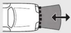
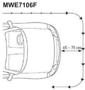
Starting at the driver's door, walk around the vehicle from the first to the last sensor (fig. 13).
The loudspeaker acknowledges each sensor detected with a short acoustic signal.
Once identification is complete, the loudspeaker emits a long acoustic signal.

NOTE
If an error occurs during this procedure, you can restart the procedure by pressing both buttons together for longer than three seconds.
9 Detection range
9.1 MWE7106
See fig. 13
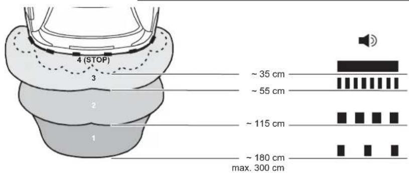
The detection range of the parking aid is divided into four zones:
- Zone 1
This zone is the first limit range. Small objects or those with poor reflective characteristics may not be detected here.
- Zone 2
Nearly all objects in this zone are displayed.
- Zone 3
Virtually all objects are displayed in this zone, but some objects may end up in the blind spot of the sensors.
- Stop zone (4)
If there are objects in this zone, the parking aid emits a continuous tone warning you to stop.
Virtually all objects are displayed in this zone, but some objects may end up in the blind spot of the sensors.
There must be no objects such as bicycle racks or spare wheels in the detection range of the sensors, as this would result in an incorrect display.
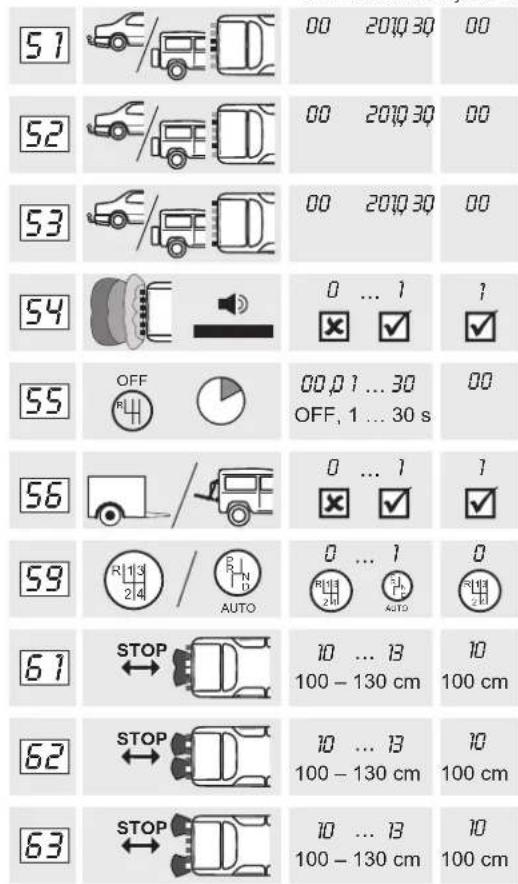
The display of fixed objects, such as a trailer coupling or a part of the spare wheel, can be suppressed (parameters 51, 52 and 53).
9.2 MWE7106F
See fig. 13
The detection range of the parking aid is divided into three zones:
- Zone 1
This zone is the first limit range. Small objects or those with poor reflective characteristics may not be detected here.
- Zone 2
Virtually all objects are displayed in this zone, but some objects may end up in the blind spot of the sensors.
- Stop zone (3)
If there are objects in this zone, the parking aid emits a continuous tone warning you to stop.
Virtually all objects are displayed in this zone, but some objects may end up in the blind spot of the sensors.
10 Setting the system
See fig. 13 to fig. 16

WARNING!
Incorrect settings can impair the operational safety.
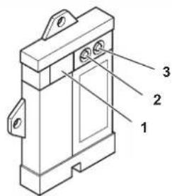
The control electronics have the following control elements:
No. in fig. 14 Description
1 Display F5 Factory settings activated
C5 Your own settings
2, 3 Buttons for setting the system

NOTE
- To save the settings, disengage and engage the reverse gear and wait for 2 s.
- To stop setting the parameters without saving your changes, or to stop the entire set-up: Do not press any button for a while.
Restoring the factory settings
▶ Press the right-hand button for longer than 5 s to access programming mode. ▶ The display now shows 01. ▶ Press both buttons for longer than two seconds. √ The display shows F5.
Only MWE7106: Suppressing use of a bicycle rack or trailer
With an optional switch you can:
- Switch over the standard stop zone (parameters 47, 48 and 49) to a higher stop zone (parameters 61, 62 and 63) if you are using a bicycle rack and this is being folded out, or ● Deactivate the parking aid while you are using a trailer.
To do this, proceed as follows:
▶ Connect pin 17 of the connection cable plug to earth using the external switch. ▶ For trailers only: Set parameter 56 to 00.
Suppress display of object fixed on the vehicle.
▶ Only MWE7106: Set parameters 51, 52 and 53 to suit your trailer coupling or your spare wheel. ▶ Only MWE7106F: Set parameters 31, 32 and 33 according to your number plate.
Only MWE7106F: Select operating mode
▶ Set parameter 39 to
- 00: if the system should be activated using the reverse gear. In this case, the yellow/blue wire must be connected to pin 4 of the control module and to the reverse gear signal. - 01: if the system should be activated when the ignition is switched on and if the system should be activated when the travel speed is between 0 and 10 km/h.
In this case, the yellow/black wire from pin 16 must be connected with the speed signal.
In addition, you can set parameter 35 to the desired time after which the sensors should be deactivated.
Only MWE7106F: Adjust outer sensors
▶ Set parameter to
- 00: if all sensors should be activated when the reverse gear is engaged.
- 01: if only the outer sensors should be activated when the reverse gear is engaged.
In this case, the yellow/blue wire must be connected to pin 4 of the control module and to the reverse gear signal.
11 Performing a functional test
Conduct the functional test of the sensors as follows:
▶ Switch on the ignition and activate the sensors.
Be very careful when you operate the device for the first time, and make sure that you familiarize yourself with the various sequences of beeps.

WARNING!
In the stop zone, some obstacles may not be detected, because they are no longer within range of the sensors (design-related characteristic).
12 Using the parking aid
MWE7106: The sensors are activated automatically when you engage the reverse gear with the ignition on or the engine running. An activation signal is emitted (two short tones).
MWE7106F: The system can be used in one of two operating modes:
- The sensors are automatically activated when the ignition is switched on. After the set time (standard: 20 s), the sensors are deactivated.
- The sensors are activated automatically once the speed of the vehicle is between 0 and 10 km/h and the ignition is switched on (factory setting).
As soon as there is an obstacle within the detection range, a repeated signal tone is emitted. As you approach, the tone sequence changes, depending on the zone in which the obstacle is, thereby indicating the distance (fig. 13).
Be very careful the first time you use the system, until you are familiar with the various sequences of beeps.

WARNING!
Stop the vehicle immediately and investigate the situation (getting out if necessary), if the following happens while you are manoeuvring:
The device first indicates an obstacle and the tone sequence speeds up normally (e.g. from slow to medium) when manoeuvring. The signal tone suddenly slows down, or no obstacle is indicated at all.
This means that the original obstacle is in the blind spot of the sensors (construction-related characteristic), and there is still a potential for collision.
13 Troubleshooting
The device shows no function.
The cables to the reversing light are not connected or are not properly connected.
The plugs for the sensors are not connected or are not correctly plugged into the control electronics.
▶ Check the plugs and make sure they lock into place.
Low error tone for three seconds after engaging reverse gear
One or more sensors are defective or no longer connected to the control electronics. The display shows the defective sensor:
- for example, E for sensor 1. Sensor 1 has the shortest connection cable, sensor 6 the longest.
- If more than one sensor is defective, they are shown in succession.
▶ Check the plugs and make sure they lock into place.
▶ Replace the defective sensor(s).

NOTICE!
The system does not work if one or more sensors are defective.
No function
The voltage supply is missing.
▶ Check the connection of the blue/black and brown wire.
No acoustic signals
The loudspeaker is switched off, or incorrectly connected.
▶ Set parameter 01 to value “1” or “2” (see chapter “Setting the system” on page 36). ▶ Check whether the loudspeaker is connected correctly.
Device indicates obstacles incorrectly
False alarms may have the following causes:
- Dirt or frost on the sensors. ▶ Clean the sensors. ● The sensors were incorrectly installed. ▶ Adjust the position of the sensors (fig. 3). ▶ If necessary, set the sensitivity of the sensors (chapter "Setting the system" on page 36).
- MWE7106: Parameters 41, 42 and 43
- MWE7106F: Parameters 21, 22 and 43
● The sensors are in contact with the chassis.
▶ Separate the sensors from the chassis.
The spare wheel is causing false alarms
▶ Set the system to suit your spare wheel (see chapter "Setting the system" on page 36).
- MWE7106: Parameters 51, 52 and 53
- MWE7106F: Parameters 31, 32 and 33
Only MWE7106: Objects on the vehicle (e.g. spare wheel) are causing false alarms
▶ Set parameters 61, 62 and 63 to suit your object 00 or 01 (see chapter "Setting the system" on page 36). Adjust the stop zone using parameters 47, 48 and 49 to suit your object (see chapter "Setting the system" on page 36).
Fault Display Codes
| Separated sensors | Control electronics display | LED display |
| Front corner sensors (1 and 6) | E1 and E6 | Green LED (front display) |
| Front middle sensors (2 and 5) | E2 and E5 | Two orange LEDs (front display) |
| Front central sensors (3 and 4) | E3 and E4 | One orange LED (front display) |
| Rear corner sensors (7 and 12) | E7 and E12 | Green LED (rear display) |
| Rear middle sensors (8 and 11) | E8 and E11 | Two orange LEDs (rear display) |
| Rear central sensors (9 and 10) | E9 and E10 | One orange LED (rear display) |
14 Warranty
The statutory warranty period applies. If the product is defective, please contact the manufacturer's branch in your country (see the back of the instruction manual for the addresses) or your retailer.
For repair and guarantee processing, please send the following items:
- Defect components ● A copy of the receipt with purchasing date ● A reason for the claim or description of the fault
15 Disposal
Place the packaging material in the appropriate recycling waste bins wherever possible.

If you wish to finally dispose of the product, ask your local recycling centre or specialist dealer for details about how to do this in accordance with the applicable disposal regulations.
16 Technical data
| MWE7106 MWE7106F | ||
| Item no.: 9101500072 9101 | 500073 | |
| Detection range: approx. 0.35 m up to 3.00 m | approx. 0.35 m up to 1.20 m | |
| Ultrasound frequency: 58 kHz | ||
| Input voltage: 10 – 32 V | ||
| Current: Max. 350 mA | ||
| Operating temperature: -35 °C to +70 °C | ||
| Certification: | 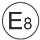 | |

NOTE
The sensors may be painted. The manufacturer recommends having the sensors painted by a specialist workshop.
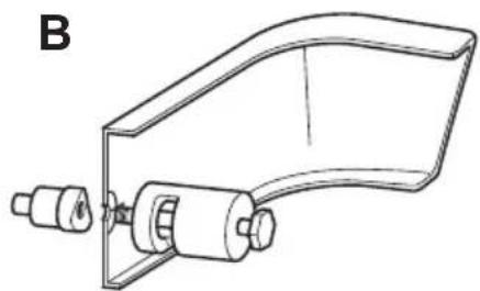
Complement to Fig. 8

10 Setting the system
Complement to Fig. 8

Complement to Fig. 8

Complement to Fig. 8

Dometic Australia Pty. Ltd.
1 John Duncan Court
Varsity Lakes QLD 4227
1800 212121
+61 7 55076001
Mail: sales@dometic-waeco.com.au
AUSTRIA
Dometic Austria GmbH
Neudorferstraße 108
A-2353 Guntramsdorf
+43 2236 908070
+43 2236 90807060
Mail: info@dometic.at
BENELUX
Dometic Branch Office Belgium
Zincstraat 3
B-1500 Halle
+32 2 3598040
+32 2 3598050
Mail: info@dometic.be
BRAZIL
Dometic DO Brasil LTDA
Avenida Paulista 1754, conj. 111
SP 01310-920 Sao Paulo
+55 11 3251 3352
+55 11 3251 3362
Dometic Group Asia Pacific
Suites 2207-11 · 22/F · Tower 1
The Gateway · 25 Canton Road,
Tsim Sha Tsui · Kowloon
+852 2 4611386
+852 2 4665553
Mail: info@waeco.com.hk
HUNGARY
Dometic Zrt. Sales Office
Kerékgyártó u. 5.
H-1147 Budapest
+36 1 468 4400
+36 1 468 4401
Dometic Italy S.r.l.
Via Virgilio, 3
I-47122 Forlì (FC)
+39 0543 754901
+39 0543 754983
Mail: vendite@dometic.it
JAPAN
Dometic KK
Maekawa-Shibaura, Bldg. 2
2-13-9 Shibaura Minato-ku
Tokyo 108-0023
+81 3 5445 3333
+81 3 5445 3339
Mail: info@dometic.jp
MEXICO
Circuito Médicos No. 6 Local 1
Colonia Ciudad Satélite
CP 53100 Naucalpan de Juárez
Estado de México
+52 55 5374 4108
+52 55 5393 4683
Mail: info@dometic.com.mx
NETHERLANDS
Dometic Benelux B.V.
Ecustraat 3
NL-4879 NP Etten-Leur
+31 76 5029000
+31 76 5029019
Mail: info@dometic.nl
NEW ZEALAND
Dometic New Zealand Ltd.
Unite E, The Gate
373 Neilson Street
Penrose 1, Auckland
+64 9 622 1490
+64 9 622 1573
Mail: customerservices@dometic.co.nz
NORWAY
Dometic Norway AS
Østerøyveien 46
N-3232 Sandefjord
+47 33428450
+47 33428459
Mail: firmapost@dometic.no
POLAND
Dometic Poland Sp. z o.o.
Ul. Puławska 435A
PL-02-801 Warszawa
+48 22 414 3200
+48 22 414 3201
Mail: info@dometic.pl
PORTUGAL
Dometic Spain, S.L.
Komsomolskaya square 6-1
RU-107140 Moscow
+7 495 780 79 39
+7 495 916 56 53
Mail: info@dometic.ru
SINGAPORE
Dometic Pte Ltd
18 Boon Lay Way 06-140 Trade Hub 21
Singapore 609966
+65 6795 3177
+65 6862 6620
Mail: dometic@dometic.com.sg
SLOVAKIA
Dometic Slovakia s.r.o. Sales Office Bratislava
Nádražná 34/A
900 28 Ivanka pri Dunaji
+421 2 45 529 680
Mail: bratislava@dometic.com
SOUTH AFRICA
Dometic (Pty) Ltd.
Regional Office
South Africa & Sub-Saharan Africa
Unit 6-7 on Mastiff Linbro Park
2008 Johannesburg
+27 11 4504978
+27 11 4504976
Mail: info@dometic.co.za
SPAIN
Dometic Spain S.L.
Avda. Sierra del Guadarrama, 16
E-28691 Villanueva de la Cañada
Madrid
+34 902 111 042
+34 900 100 245
Mail: info@dometic.es
SWEDEN
Dometic Scandinavia AB
Gustaf Melins gata 7
Dometic Switzerland AG
Riedackerstrasse 7a
CH-8153 Rümlang
+41 44 8187171
+41 44 8187191
Mail: info@dometic.ch
UNITED ARAB EMIRATES
Dometic Middle East FZCO
P. O. Box 17860
S-D 6, Jebel Ali Freezone
Dubai
+971 4 883 3858
+971 4 883 3868
Mail: info@dometic.ae
UNITED KINGDOM
Dometic UK Ltd.
Dometic House, The Brewery
Blandford St. Mary
Dorset DT11 9LS
+44 344 626 0133
+44 344 626 0143
Mail: sales@dometic.co.uk
USA
Dometic RV Division
1120 North Main Street
Elkhart, IN 46515
+1 574-264-2131
- MAGICWATCH
- MWE7106, MWE7106F
- SUPPLEMENT TO FIG
- TABLE OF CONTENTS
- EXPLANATION OF SYMBOLS
- WARNING
- NOTICE
- NOTE
- SAFETY AND INSTALLATION INSTRUCTIONS
- SCOPE OF DELIVERY
- MWE
- MWE7106F
- ACCESSORIES
- INTENDED USE
- INSTRUCTIONS BEFORE INSTALLATION
- PAINTING THE SENSORS
- DETERMINING THE PLACE OF INSTALLATION FOR THE SENSORS
- SUPPLEMENTARY TO FIG
- FITTING THE PARKING AID
- NOTICE! RISK OF MALFUNCTION
- CONNECTING THE PARKING AID
- REGISTERING AND IDENTIFYING SENSORS
- DETECTION RANGE
- SEE FIG
- ZONE
- STOP ZONE (4)
- STOP ZONE (3)
- SETTING THE SYSTEM
- NO. IN FIG. 14 DESCRIPTION
- RESTORING THE FACTORY SETTINGS
- ONLY MWE7106: SUPPRESSING USE OF A BICYCLE RACK OR TRAILER
- SUPPRESS DISPLAY OF OBJECT FIXED ON THE VEHICLE
- ONLY MWE7106F: SELECT OPERATING MODE
- SET PARAMETER 39 TO
- ONLY MWE7106F: ADJUST OUTER SENSORS
- SET PARAMETER TO
- PERFORMING A FUNCTIONAL TEST
- USING THE PARKING AID
- TROUBLESHOOTING
- THE DEVICE SHOWS NO FUNCTION
- LOW ERROR TONE FOR THREE SECONDS AFTER ENGAGING REVERSE GEAR
- NO FUNCTION
- NO ACOUSTIC SIGNALS
- DEVICE INDICATES OBSTACLES INCORRECTLY
- THE SPARE WHEEL IS CAUSING FALSE ALARMS
- ONLY MWE7106: OBJECTS ON THE VEHICLE (E.G. SPARE WHEEL) ARE CAUSING FALSE ALARMS
- WARRANTY
- DISPOSAL
- TECHNICAL DATA
- COMPLEMENT TO FIG
- DOMETIC AUSTRALIA PTY. LTD
- AUSTRIA
- DOMETIC AUSTRIA GMBH
- BENELUX
- DOMETIC BRANCH OFFICE BELGIUM
- BRAZIL
- DOMETIC DO BRASIL LTDA
- DOMETIC GROUP ASIA PACIFIC
- HUNGARY
- DOMETIC ZRT. SALES OFFICE
- DOMETIC ITALY S.R.L
- JAPAN
- DOMETIC KK
- MEXICO
- NETHERLANDS
- DOMETIC BENELUX B.V
- NEW ZEALAND
- DOMETIC NEW ZEALAND LTD
- NORWAY
- DOMETIC NORWAY AS
- POLAND
- DOMETIC POLAND SP. Z O.O
- PORTUGAL
- DOMETIC SPAIN, S.L
- SINGAPORE
- DOMETIC PTE LTD
- SLOVAKIA
- DOMETIC SLOVAKIA S.R.O. SALES OFFICE BRATISLAVA
- SOUTH AFRICA
- DOMETIC (PTY) LTD
- REGIONAL OFFICE
- SOUTH AFRICA & SUB-SAHARAN AFRICA
- SPAIN
- DOMETIC SPAIN S.L
- SWEDEN
- DOMETIC SCANDINAVIA AB
- DOMETIC SWITZERLAND AG
- UNITED ARAB EMIRATES
- DOMETIC MIDDLE EAST FZCO
- UNITED KINGDOM
- DOMETIC UK LTD
- USA
- DOMETIC RV DIVISION
Brand : DOMETIC
Model : MagicWatch MWE 7106F
Category : Refrigerator