
SC120DA - Drill MAKITA - Free user manual and instructions
Find the device manual for free SC120DA MAKITA in PDF.



| Product Type | Battery-operated Rod Cutter |
| Brand | MAKITA |
| Model | SC120DA |
| Cutting Capacities | Mild steel M8, M10, M12 |
| Cutting Speed | 2.5 seconds |
| Total Length | 316 mm |
| Net Weight | 4 kg |
| Rated Voltage | 12 V DC |
| Battery Type | Compatible MAKITA Lithium-ion |
| Rapid Charger | DC1439 or DC1414 |
| Typical Charging Time | Approximately 9 to 45 minutes depending on battery |
| Charge Indicator | Green/red LED indicator |
| Cutting System | Hydraulic oil pressure |
| Recommended Oil | Original MAKITA #46 Oil |
| Trigger | Variable speed, automatic return to OFF position |
| Included Blades | M8 type A and B |
| Optional Accessories | Blades M10/M12, stopper M12 |
| Safety | Protection against short circuit, overheating, and overload |
| Maintenance | Periodic oil refill, replacement of blades and stopper |
Frequently Asked Questions - SC120DA MAKITA
User questions about SC120DA MAKITA
0 question about this device. Answer the ones you know or ask your own.
Ask a new question about this device
Download the instructions for your Drill in PDF format for free! Find your manual SC120DA - MAKITA and take your electronic device back in hand. On this page are published all the documents necessary for the use of your device. SC120DA by MAKITA.
USER MANUAL SC120DA MAKITA
The followings show the symbols used for the tool. Be sure that you understand their meaning before use.
Symboles
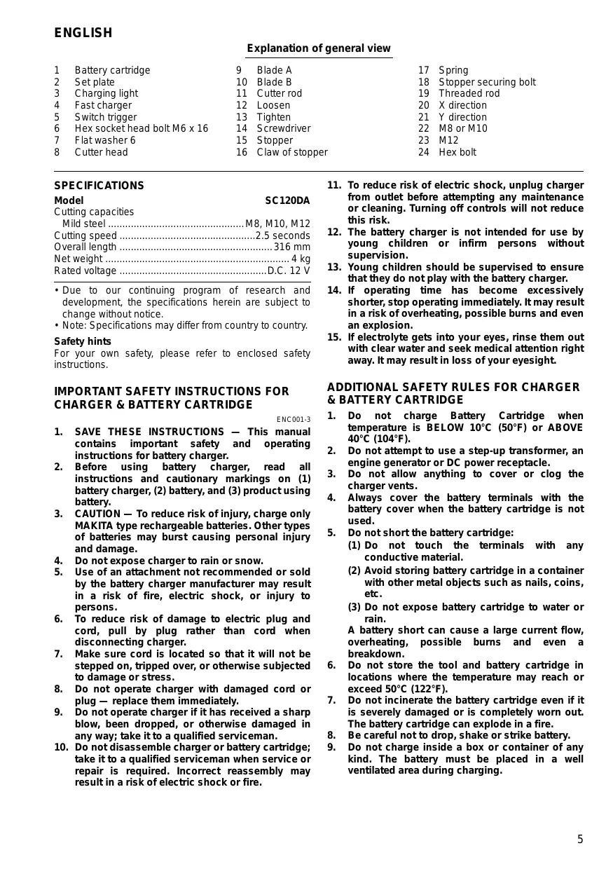
Explanation of general view
1 Battery cartridge
2 Set plate
3 Charging light
4 Fast charger
5 Switch trigger
6 Hex socket head bolt M6 x 16
7 Flat washer 6
8 Cutter head
9 Blade A
10 Blade B
11 Cutter rod
12 Loosen
13 Tighten
14 Screwdriver
15 Stopper
16 Claw of stopper
17 Spring
18 Stopper securing bolt
19 Threaded rod
20 X direction
21 Y direction
22 M8 or M10
23 M12
24 Hex bolt
SPECIFICATIONS
Model SC120DA
Cutting capacities Mild steel .M8,M10,M12
Cutting speed 2.5 seconds
Overall length 316 mm
Net weight 4 kg
Rated voltage .D.C. 12 V
- Due to our continuing program of research and development, the specifications herein are subject to change without notice.
- Note: Specifications may differ from country to country.
Safety hints
For your own safety, please refer to enclosed safety instructions.
IMPORTANT SAFETY INSTRUCTIONS FOR CHARGER & BATTERY CARTRIDGE
ENC001-3
- SAVE THESE INSTRUCTIONS - This manual contains important safety and operating instructions for battery charger.
- Before using battery charger, read all instructions and cautionary markings on (1) battery charger, (2) battery, and (3) product using battery.
- CAUTION - To reduce risk of injury, charge only MAKITA type rechargeable batteries. Other types of batteries may burst causing personal injury and damage.
- Do not expose charger to rain or snow.
- Use of an attachment not recommended or sold by the battery charger manufacturer may result in a risk of fire, electric shock, or injury to persons.
- To reduce risk of damage to electric plug and cord, pull by plug rather than cord when disconnecting charger.
- Make sure cord is located so that it will not be stepped on, tripped over, or otherwise subjected to damage or stress.
- Do not operate charger with damaged cord or plug - replace them immediately.
- Do not operate charger if it has received a sharp blow, been dropped, or otherwise damaged in any way; take it to a qualified serviceman.
-
Do not disassemble charger or battery cartridge; take it to a qualified serviceman when service or repair is required. Incorrect reassembly may result in a risk of electric shock or fire.
-
To reduce risk of electric shock, unplug charger from outlet before attempting any maintenance or cleaning. Turning off controls will not reduce this risk.
- The battery charger is not intended for use by young children or infirm persons without supervision.
- Young children should be supervised to ensure that they do not play with the battery charger.
- If operating time has become excessively shorter, stop operating immediately. It may result in a risk of overheating, possible burns and even an explosion.
- If electrolyte gets into your eyes, rinse them out with clear water and seek medical attention right away. It may result in loss of your eyesight.
ADDITIONAL SAFETY RULES FOR CHARGER & BATTERY CARTRIDGE
- Do not charge Battery Cartridge when temperature is BELOW 10^ (50^) or ABOVE 40^ (104^) .
- Do not attempt to use a step-up transformer, an engine generator or DC power receptacle.
- Do not allow anything to cover or clog the charger vents.
- Always cover the battery terminals with the battery cover when the battery cartridge is not used.
- Do not short the battery cartridge:
(1) Do not touch the terminals with any conductive material.
(2) Avoid storing battery cartridge in a container with other metal objects such as nails, coins, etc.
(3) Do not expose battery cartridge to water or rain.
A battery short can cause a large current flow, overheating, possible burns and even a breakdown.
- Do not store the tool and battery cartridge in locations where the temperature may reach or exceed 50^ (122^) .
- Do not incinerate the battery cartridge even if it is severely damaged or is completely worn out. The battery cartridge can explode in a fire.
- Be careful not to drop, shake or strike battery.
- Do not charge inside a box or container of any kind. The battery must be placed in a well ventilated area during charging.
ADDITIONAL SAFETY RULES FOR MACHINE
- If the blades are deformed, damaged or cracked, replace them with new ones immediately. Deformed, damaged or cracked blades can cause machine trouble, eventually leading to serious injury.
- Be careful when using the machine in high or elevated locations. Parts of cut threaded rods may fall unexpectedly, causing serious injury.
- Keep hands away from blades and surrounding areas.
OPERATING INSTRUCTIONS
Installing or removing battery cartridge (Fig.1)
To remove the battery cartridge, pull out the set plate and withdraw the battery cartridge from the machine.
To install the battery cartridge, align its tongue with the groove in the housing and slip it into place. Snap the set plate back into place.
SAVE THESE INSTRUCTIONS.
Charging (Fig.2)
Plug the fast charger into your power source. The charging light will flash in green color. Insert the battery cartridge so that its plus and minus terminals are on the same sides as their respective markings on the fast charger. The charging light color will change from green to red and charging will begin. The charging light will remain lit steadily during charging. When the charging light color changes from red to green and a tone sounds steadily for approx. 5 seconds, charging is complete. Unplug the charger from the power source.
(Note: Refer to the table below for the charging time.)
| Battery cartridge | Fast charger | |
| DC1439 | DC1414 | |
| 1202 or 1202A | Approx. 14 min. | Approx. 45 min. |
| 1201 or 1201A | Approx. 12 min. | Approx. 40 min. |
| 1200 or 1200A | Approx. 9 min. | Approx. 30 min. |
CAUTION:
- If the battery cartridge is new, or has not been used for a long time, it may not accept a full charge. You can recharge the battery cartridge fully after discharging it completely a couple of times.
- If the battery cartridge is warm, the charging light may flash in red color. Let it cool before charging.
- If the charging light flashes alternately in green and red, and a tone sounds "beep, beep, beep, ....", a problem exists and charging is not possible. The terminals on the charger or battery cartridge are clogged with dust or the battery cartridge is worn out or damaged.
- If charging two battery cartridges in succession, give the charger 15 minutes to cool down between the two.
Switching ON and OFF (Fig. 3)
CAUTION:
Before inserting the battery cartridge into the machine, always check to see that the switch trigger actuates properly and returns to the "OFF" position when released.
To switch on, press the trigger. To switch off, release the trigger.
Variable trigger speed control (Fig. 3)
The speed varies from 0 to maximum, depending on the pressure applied to the trigger. The more the trigger is pressed, the faster the machine runs.
Replacing blades (Fig.4)
Important:
Always be sure that the machine is switched off and battery cartridge is removed before replacing the blades.
M8 blades are factory-installed on the machine. When cutting M10 or M12 threaded rods, replace the M8 blades with M10 or M12 blades which are available as optional accessories. There are two types of blades for each size; type A should be installed on the cutter head and type B on the cutter rod. Check the type (example: M8A or M8B) engraved on the side of the blades and install them at the correct position.
To replace the blades, first remove the hex socket head bolts which secure them.
Replacing stopper (Fig. 5 & 6)
Important:
Always be sure that the machine is switched off and the battery cartridge is removed before replacing the stopper.
The stopper for M8 or M10 blades is factory-installed on the machine. When cutting M12 threaded rods, replace the stopper for M8 or M10 blades with the stopper for M12 blades which is provided as standard equipment.
To replace the stopper, remove the bolt which secures it. Install the stopper on the machine with its claw facing forward or upward.
Cutting operation
- To mount the threaded rod, position the stopper with its claw facing forward as shown in Fig. 7. With the M8 or M10 threaded rod, move the machine head to the threaded rod either in the X direction shown in Fig. 7-1 or in the Y direction shown in Fig. 7-2. With the M12 threaded rod, move the machine head in the Y direction.
- Mount the threaded rod so that its thread engages that on the blade A.
CAUTION:
Always mount the threaded rod correctly as shown in Fig. 8, never as shown in Fig. 9. Serious injury may result.
- After mounting the threaded rod, position the stopper as shown in Fig. 10 to secure the threaded rod squarely against the blades.
CAUTION:
Always mount the threaded rod so that it covers the entire width of blades B as shown in Fig. 11-1. If you try to cut the threaded rod mounted as shown in Fig. 11-2, the thread on the threaded rod may break.
- Pull the trigger. The cutter rod moves forward to cut the threaded rod without crushing the thread on the threaded rod. Keep the trigger pulled until the threaded rod is completely cut.
- Release the trigger, and the cutter rod will automatically return to its original position.
NOTE:
- The cutter rod will not return to its original position even if you release the trigger until the cutter rod moves as far as it can.
-
The cutter rod will not move forward even if you pull the trigger again until the cutter rod has returned completely to its original position.
-
After cut-off, remove the machine head from the threaded rod after positioning the stopper as shown in Fig. 7.
MAINTENANCE
CAUTION:
Always be sure that the machine is switched off and the battery cartridge is removed before carrying out any work on the machine.
Oil replenishment (Fig. 12)
This is an oil-pressure type cutter. When shipped from the factory, it is filled with pressure oil. Do not add oil as long as the machine performs well. When the oil-pressure is not enough to cut threaded rod, replenish the oil as follows. Use only Makita genuine oil #46.
- Mount the threaded rod on the machine as described before.
- Pull the trigger. Release the trigger just before the threaded rod is completely.
- Remove the battery cartridge from the machine.
- Remove the hex bolt which caps the oil hole. Replenish oil, being careful not to allow any oil into the motor.
- Replace the hex bolt and tighten securely.
- Install the battery cartridge on the machine and complete the threaded rod cut-off.
- Repeat the above procedures two or three times.
To maintain product safety and reliability, repairs, maintenance or adjustment should be carried out by a Makita Authorized Service Center.
Descriptif
Nominate spanning. DC 12 V
TEXHUNECKNE XAPAKTEPNCTNKN
Mopelb SC120DA
Pexyua cnocoboctb Hn3kooyrpeoiccta TaIb....M8,M10,M12
Ckopoctb pe3aHnra 2,5cekyndbl
O67aJdIHa 316 MM
Bec HeTTo 4.0Kr
HomHaJIbHoe HapRJaXeHHe. ..IocT.tok 12 B
BcneDCTBNE HauSeI npOdoXaHOeCn npOrpAMMbIOncKa n pa3pa60ToK texHueckNe xapAKeTpNCtKNMOrY 6bTbIM3MeHeHb 6e3 yBeDoMEnHn.
- Плимочаиме: Тхическne ХаразКерпстually MOrут pa3ЛИЧаТьСВ В 3aВИСИМОСТИ ON DTcaPahl.
BAXHbIE INHCTPYKcIIN IIO BE3OJACHOCTN JJIa 3APrIHOTO YCTPOIcTBA N BATAPEHORO KAPTPuIXA
- COXPAHNTE 3TN INHCTPYKUIN - 3ta 6poIoupa coDEpexNt BaxhBie INHCTPYKUIN NO 6e3onacHocTN I KcNpIyatauIN DnA 6batapeHOrO 3apdHOrO yctpoCTBA.
2.пелднрьбанem6aTaepHoro3apHoro yctpoiCTBa npOHTaIe BCE nHcTpyKUnn npedynpejkaioNe 3ameuHaN OTHocTeJbHo 6aTaepHoro 3apHoro yctpoiCTBa (1),6aTaep (2)ии3dJIy,ncnoIb3yUoIero6aTaapeo (3). - INPEDYNPEXKDEHNE -ДЯумьшени ОпаСНСТРВМБI 3APЖКАТе TOLBJKO песзаржамbleбатерфимыMAKITA. Дугге ТИПБбатермогуВЗрвБс, Вьзв песональню ТравмУ Или NOВржденс.
- He noOBBepraute 3apHnOe yCTpoIcTBO BO3dEChTBnIO DOxJNm Chera.
- Исторьогане писецинения 6атугову
3ардогону усторьва, КOTOPОЕ He pekomehdyetси и He npOdaetcnpOIN3BODITeHem, MOXTп ривс'tи К onaHOCHTи NOXAPA, nopaXeHem
3NEKtprueckHM TOKOM NII IN TpABME nepcoHana.
6.ДЯУмьшениOnachoctи NOBpeKdHnA 3JIeKtpnueckoBNIKIuShypa TnHnTe 3a BUNKy,aHe 3a Uhyp npn OTcoeHNHeHn 3aprADHOYcTpoiCtBa. - Y6eHntecb, yTo uHyp pacnOIOxeh TaK, qTo Ha Hero He 6yDt HAcTyNaTb, OTKnIOuTaB nn NoDBePraTb NOBpeXDeHNrM NN Harpy3kAm DpynMn CnocobAmn.
8.He 3KcPJIyATnpyTe 3apdHoe yctpoCTBO c NOBpeXDeHHbIM shypom nIIN BUNKOI - 3aEMHeYTe INx HEmDJIeHNHO.
9.He 3KcIpyaTnpyTe 3apAHHoe yCTpOHTBO,ecnno Hemy CnIbHO yApuHnI, yPoHNn IINIOBpeHnI KAKM-Im6o DpyrHM cnOcObOM,OTHECnE ero KBaINΦmNcpOBaHMOY cneuaHncty no Texo6cnJxHBAnHIO.
10. He pa36bpaIte 3apnHoe yctpoiCTBO nIkpTpIaXk 6aTape; npn Heo6xOdmocTnTexo6cIyJXuBaHnI nn pEmOnTA OTHeCtTe erKBAJIHnIuPBoAHNOMy CneUaHnCTy noTexo6cIyJXuBaHnIO. HnpabunlbHaN NOBTopHaNc6Opka MoKet IpnMBeCTN K ONaChOCTN nopaxEHHN 3NeKtPrueckm TOKOM NIN NOKApY.
11.ДЯумehbш�нonachoctn nopaxhenyaNEKtpneckmTOKOMOTcoeDHHTe3apdHoeyctpoiCTBOIPO3eTKnpepeJIIObONbITKOYxOdaIMNCHCTKN.BbIKIOUChEHnOprHOBuypabJIENHaHEymehbWHT3TyOnaCHOCTb.
12.БатAPEHoe 3apdHoe yctpoCTBO He npedHa3HaueHo nIa IcNoIb3OBAHnMaJIeHbKIMN DeTbMn IIN HeMOUHbIMI NIOdbMn 6e3 npCMOTpa.
13. CnEpyET nPcMATPBaTb 3a MaIeHbKIMN DeTbMn, YTOb6y6eNTbC, YTO OHn He 6ydturPaTb C 6aTaPeHbIM 3apHbIM yCToPCTOBM.
14. EcnBpem3Kcnpyatau3HaunTeIbHO cokpaTnOcB, HEmedJeHNO pKePaTnE 3KcnpyatauIO.OHa MoKet npNBecTN K OanaCHOCT NpeperpeBa, BO3MOXhIM OxOram N daXe B3pbIBy.
15. Ecnn 3neKtponnt nonaet Bam B rna3a, npomoi Te xu HCTOIN BOIOH NHEMeJdIeHHO 6obpatntecb 3a MednunHcKOM nOmoIbIO. B npOTNBOM Cnyae, BO3MOXHa NOTepra 3peHnR.
ДОПЛНITEЛБHBIE ПAPВИА БЕЗПАСХОТNДЛЯ 3APДHΟΤ ΥСТЮСТВА И BATAPEHΟΤΟ ΚΑΡΤΡΙΝΚA
- He 3apjkaTe 6aTapeHbI KapTpndK, KOrda Tempepatya coCTabJIeT HIXKE 10^ nII BBIUE 40^
- He nbItaTeBc bNcNoJIb3OaBb NobIbIaOuItn TpaHcΦopMaTOp, rEhepatOp dBnIaTeIa NIIPO3eTKy NTtAHIN NOCTOHHORO TOKA.
- He DonyckaTe 3aKpbTnN nIi 3acOpHnA BeHTnJIaUOnHHbIX OTBepCTn 3apJHO yctPoIeCTBa HNKaKMn NpeDMeTaMn.
-
Korga He nCnOJb3yete 6atapeHbI KaTpndK, Bcerga 3akpbIbAitE 6atapeHbIe KJIeMMbl 6atapeHoi KpbIiKoI.
-
He 3akopauBaIte 6atapeHbI KaptpnJx:
(1) He npikacaiTecb K KJIeMMam HnKaKIMnpoBODaUMM MaTePnaJAmN.
(2)ИзбeraиTe xpaHEnHЯ 6aTapeHOro KaptrnДжа B KOHTeHHepe C dprYmM MeTaNIIuYeCKMn npEdMeTaMn, TakMn, KaK rBO3dN, MOHETbI N.T.D.
(3) He noDBepraTe 6aTapeHbI KAPTpNIX BO3DeiCTBnIO BODI INI DOxJa.
3aKopauBaHBeN 6aTapen MoKet npnBectn K 60bnomy notoky Toka, nepereby, BO3MOKhbIM OXOFAM dAke NOLOMKe.
- He xpaHnTe HNCTpymEnI 6aTapeHbI KApTpIaX B MeCtTx, rge Tempepatya Moket DoCTHy NJI pBeBicInb 50^
7.He cKnraite BaapeHbI KapTpndx,daKe ecnn OH CNbHO NOBpeXdEN IIN NONHO Bblen H3 CTPOJ. BaapeHbI KapTpndx MOXET B3OPBA TbCB R OTHe. - BybTe oCtOpOxHbI, YTo6bI He ypoHnTb, He TpAChn HIn He ydApNTb 6aTapeIO.
9.He 3apJxJaTe BHyTpN Kopo6Kn NnKoHTeHepa IIO6O BnDa.Bo BpEma 3apJKn CJeDyET NOpCtNTb 6aTaPeEO B O6NaCTb CxopoUeBENTINLJIeH.
UcTaHOBKa nIy uJaJIeHne 6aTapeHOrO kApTpIxDka (Pnc.1)
YtobIy ydaHnTb 6aTapeHbI KApTpNdx, NOTHInTe YctAHOBOChHyIO PnactHy N BbTaAsTe 6aTapeHbI KApTpNdx N3 IHCTpyMeHTA. YtobIy BCtABnTb 6aTapeHbI KApTpNdx, COBMeCTNte erO r3bHOK C KaHaBKO HApKpNyce N3aDbNVbTe ERO Ha MeCTO. CNeDeyET ONHOCTbO 3aKpbITb PnTIy YcTAHOBNk NepeD nCNoJIb30BaHNem IHCTpyMeHTA.
3apnka (Pnc.2)
IopdknUOHTe 3apRHDoe yCTPOJCTBO DnA B6tCPoJ 3apRDKK BaWaeMy NCTOCHNK PNTAHNJa. JAMna 3apRKn 6yETMnATB 3eNEHbIM CBTOM. BCTABBe 6atapeHbIK KAPTPrDx TAK, YTObbl KLEMMbPI NIOUC MHNyc Ha 6atapeIHOMK aPrtDjKe HauODJIncB C TEs Xe C STOpON, YTOu N COOTBeTCTBYUQIe 3HAuKN Ha 3apRHDoe yCTPOJCTBO DnA B6tCTPOJ3APRkDN. KOrDa 6atapeHbIK KAPrDx BCTABNeH, CBET JAMNbI 3apRKn I3MEHNTc R 3EJIHOH RaKpChB,N HAuHNaEtC3apRkKa. BbICBeUHbAHe JAMNbI 3apRKn 6yET NOCTOHHB Mo BVPeMa 3apRKn. 3apRkDa 3aBepWHTC, KOrDa UCBET JAMNbI 3apRKn I3MEHNTc R KpACHOHa 3eJIbIK, IN B TceHHe NpIbIMTeJIbHO5 CEkyND 6yET 3ByuTaB HepePBbHbIK 3BykoBOi CnHAn. NocLe 3apRKn OTKLIQUHTe 3apRHDoe yCTPOJCTBO OTNCTOHHKA NTAHNIA.
EC-DECLARATION OF CONFORMITY
Model; SC120DA
We declare under our sole responsibility that this product is in compliance with the following standards of standardized documents,
EN60745, EN55014
in accordance with Council Directives, 2004/108/EC and 98/37/EC.
FRANÇAISE
DéCLARATION DE CONFORMITÉ CE
Modèle ; SC120DA
Responsible manufacturer:
Fabricant responsible :
Authorized Representative in Europe:
Michigan Drive, Tongwell, Milton Keynes, Bucks MK15 8JD, ENGLAND
PORTUGUES
EU-DEKLARATION OM KONFORMITET
Model; SC120DA
Michigan Drive, Tongwell, Milton Keynes, Bucks MK15 8JD, ENGLAND
ENGLISH
Noise and Vibration of Model SC120D
The typical A-weighted sound pressure level is 74 dB (A). The noise level under working may exceed 85 dB (A). - Wear ear protection.
The typical weighted root mean square acceleration value is not more than 2.5m / s^2
FRANCAISE
Uymn Bn6paunr moJeIN SC120D
TINHbI A-B3BWeHbI yPoBeHb 3ByKOBOrO daBHeHH COCTaBJIeT 74 d5 (A).
YpOBeHbIyMa npn pa6Ote MoKeT npEbbIaTb 85D(A).
- HaedeBaIte 3aunTy dIy uwei. -
TINHHOE B3BeseHHoe 3HaueHne KBaIpaTHORO KOPHnyCKOpEHN CoCTaBnAET He 60nee Yem 2,5 M/c².