
FlyTec FT200 - Roller blind DOMETIC - Free user manual and instructions
Find the device manual for free FlyTec FT200 DOMETIC in PDF.


| Product Type | Roller awning |
| Brand | Dometic |
| Model | FlyTec FT200 |
| Dimensions (deployed) | Approximately 200 x 250 cm (depending on configuration) |
| Weight | Approximately 15 kg |
| Canopy material | Coated acrylic, UV-resistant |
| Available colors | White, beige, gray (depending on range) |
| Operation | Manual (crank) or motorization optional |
| Main functions | Sun protection, shading, extension of outdoor living space |
| Additional features | Anti-wind system, adjustable tilt, easy storage |
| Maintenance and cleaning | Clean with clear water and mild soap, avoid harsh products |
| Safety | Safe deployment and retraction, crank lock |
| Spare parts and repairability | Replacement canopy, crank, articulated arms available from Dometic |
| Warranty | 2 years (subject to conditions) |
| General information | Recommended for caravans, motorhomes and terraces |
Frequently Asked Questions - FlyTec FT200 DOMETIC
User questions about FlyTec FT200 DOMETIC
0 question about this device. Answer the ones you know or ask your own.
Ask a new question about this device
Download the instructions for your Roller blind in PDF format for free! Find your manual FlyTec FT200 - DOMETIC and take your electronic device back in hand. On this page are published all the documents necessary for the use of your device. FlyTec FT200 by DOMETIC.
USER MANUAL FlyTec FT200 DOMETIC
FlyTec FT200
EN Flyscreen for sliding doors Operating manual....8


Please read this instruction manual carefully before first use, and store it in a safe place. If you pass on the product to another person, hand over this instruction manual along with it.
Contents
1 Explanation of symbols....8 2 Safety instructions....8 3 Scope of delivery 9 4 Intended use....9 5 Installing the flyscreen....10 6 Using the flyscreen .....13 7 Cleaning and maintenance....13 8 Warranty ....14 9 Disposal ....14 10 Versions....14
1 Explanation of symbols

NOTICE!
Indicates a situation that, if not avoided, can result in property damage.

NOTE
Supplementary information for operating the product.
2 Safety instructions
Please observe the safety instructions and stipulations issued by the vehicle manufacturer and service workshops.
The manufacturer accepts no liability for damage in the following cases:
• Faulty assembly or connection • Damage to the product resulting from mechanical influences
• Alterations to the product without express permission from the manufacturer • Use for purposes other than those described in the operating manual

NOTICE!
- If you do not have sufficient technical knowledge for installing components in vehicles, you should have a specialist install the fly-screen in your vehicle.
- Check whether the dimensions of the flyscreen fit your vehicle. • Installation of the flyscreen requires two people.
3 Scope of d
No. in
fig. 1,
page 3
Quantity Description
11 Skirting board
21 Cassette profile with flyscreen and guide cables
31 C pillar cover
4 7 Blind rivet (4 x 8 mm with stainless steel mandrel)
51 Fastening screw M5 x 30 mm and M5 nut
61 Guide rail above
71 Safety clip and screw M2.5 x 6
81 Deflection screw M4 with safety clip and screw M2.5 x 6
- Installation and operating manual
The screws for fastening on the vehicle are not included in the scope of delivery.
4 Intended use
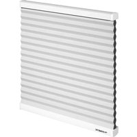
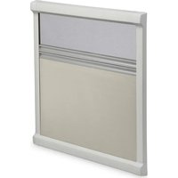
The Dometic FlyTec FT200 is a flyscreen for sliding doors on camper vans which can be slid or folded horizontally. For available versions see the table, page 14.
5 Installing the flyscreen
5.1 Notes on installation
- Before installing the flyscreen, check whether any vehicle components could be damaged by the installation of the flyscreen (such as cupboards).
- For safety reasons, note the location of existing wiring harnesses, wires and other components within the installation area, in particular those which are not visible, when installing the flyscreen (when drilling or screwing, etc.).
5.2 Preparing the vehicle
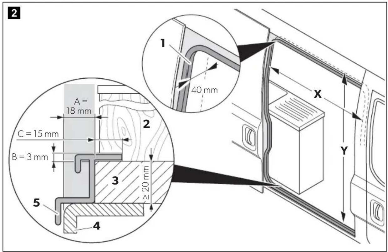
Measuring the opening (fig. 2, page 3)
Please observe the following instructions when measuring:
- The installation opening should not have been made smaller through added strips, coverings, fixtures, etc.
- The installation opening must have the minimum width of X and minimum height of Y:
FlyTec version (ref. no.) Minimum width X Minimum height Y
9104117297 and 9104117296 1298 mm 1765 mm
9104117387 and 9104117388 1128 mm 1492 mm
- Behind the rear sealing of the door (1), there needs to be a minimum of 40 mm space for the flyscreen to be installed.
- There needs to be a space with a width of A = 18 mm between the outer edge of the bodywork floor (4) and fitted cabinets (2) (e.g. kitchen).
• The skirting board (5) needs the following space:
- There needs to be a space with a width of A = 18 mm between the outer edge of the bodywork floor (4) and the edge of the interior fittings base (3).
- A space with a height of B = 3 mm and a depth of C = 15 mm needs to be available from the edge of the interior fittings base (3).
You may need to adapt fitted cabinets (2) and the interior fittings base (3).
- The flyscreen must be screwed directly to the sheet-metal bodywork at the top and not just on the panelling or the interior fittings. It is usually sufficient to screw it on to the base of the interior fittings.
▶ Measure the installation opening in your vehicle and check whether the dimensions of the flyscreen fit your vehicle.
Trimming the opening (depending on the vehicle)
▶ If necessary, remove add-on parts that interfere (such as bottom end strips or bodywork) in the installation opening.
To be able to install the skirting board (fig. 1 1, page 3) flush, you may need to trim the existing fixtures (such as floors or cabinets).
▶ Mark the following (fig. 2, page 3):
- Size A = 18 mm (width of the bottom part of the skirting board), measured from the edge of the sheet-metal bodywork - Size B = 3 mm (height of the skirting board).
If necessary, trim the existing fixtures with a suitable tool, such as an oscillating saw.
Smooth and clean the cut edges.
5.3 Pre-installing the rails
Cassette profile, skirting board and upper guide rail
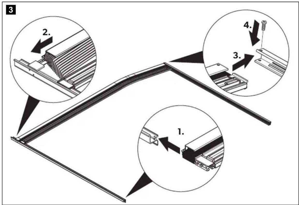
The cassette profile, skirting board and upper guide rail must be assembled lying on the ground (fig. 3, page 4) before being placed in the vehicle.
Check whether the cover profile can be inserted between the C pillar and interior fittings. You may need to adapt the contour by trimming. Guide the lower slider of the handle strip along with the cassette profile into the skirting board. Pull the cassette and handle strip apart by a bit and then slide the cassette profile onto the nose on the skirting board. Secure the cassette profile with the screw (M5 x 30 mm) and M5 nut on the upper guide rail. Insert the cover for the C pillar into the cassette so that the drill holes are located one above the other and secure the two components with three blind rivets (4 x 8 mm with stainless steel mandrel) without riveting them (fig. 4, page 4). Secure the deflection screw M4 (fig. 5 1, page 5) to the skirting board. Fit the guide cables into the bottom and top deflection screw (fig. 5 2 and 3, page 5).

NOTICE! Risk of breaking the lower plastic slider
Be careful when you are lifting and positioning the flyscreen and do not bend or tilt the skirting board.
Have two people carefully lift the pre-assembled flyscreen and position it in the vehicle.
Adjusting the top guide rail
Check whether the contour and position of the upper guide rail fit the vehicle (see enlarged inset in fig. 7, page 5). You may need to adjust the upper guide rail by cutting the two upper legs.
5.4 Securing the flyscreen in the vehicle

NOTICE!
- Choose suitable screws depending on the floor and roof construction. Make sure that you do not drill through the floor and roof.
Securing the skirting board and upper guide rail
▶ Align the position of the cassette profile perpendicular to the skirting board and the upper guide rail. ▶ Secure the skirting board to the bottom plate (fig. 6, page 5) with five countersunk screws (∅ 4 mm). ▶ Secure the upper guide rail to the vehicle (fig. 7, page 5) with four countersunk screws (∅ 4 mm).
5.5 Completing installation
Riveting the cassette profile with the cover profile for the C pillar (fig. 8, page 6)
▶ Put all the blind rivets (4 x 8 mm with stainless steel mandrel) through the drill holes and rivet the components using a hand riveter.
Tensioning the guide cables

NOTICE!
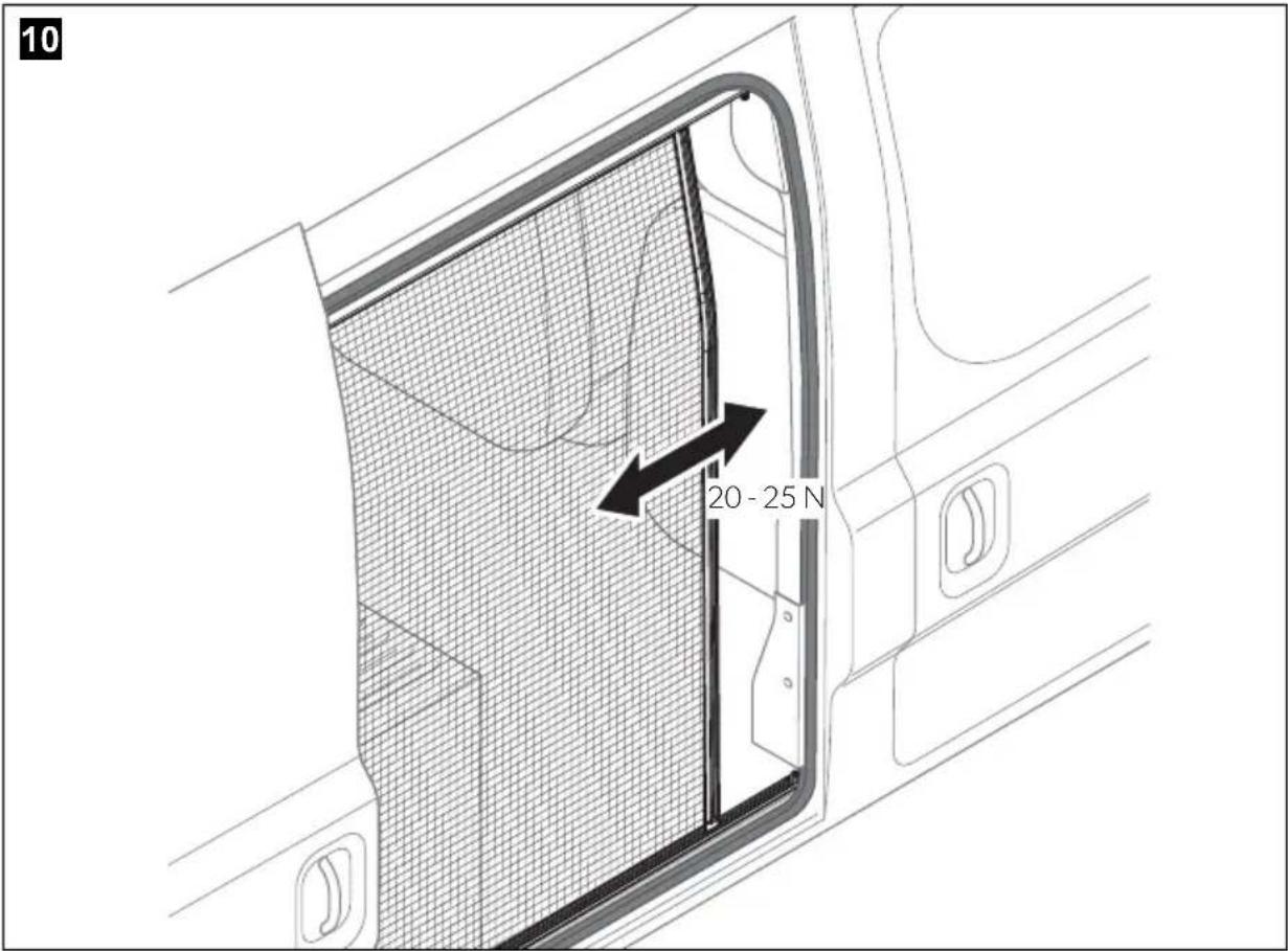
The tension of the cables affects the guidance and smooth running of the handle strip. By changing the tension of the upper and lower cable, you can adjust the parallel orientation of the handle strip to the right door edge. Do not tension the cables more than 25 Newton.
▶ Tension the guide cables on the deflection screws on the skirting board and the top guide rail (fig. 9, page 6). ▶ Secure the safety clips onto the deflection screws each with a screw (M2.5 x 6 mm) (fig. 9 1 and 2, page 6).
6 Using the flyscreen

NOTICE! Beware of damage!
The sliding door of the vehicle may be closed only when the flyscreen is fully open.
Closing the flyscreen
▶ Pull the handle strip on the flyscreen to close the flyscreen (fig. 10, page 7).
Opening the flyscreen
▶ Pull the handle strip on the flyscreen to open the flyscreen (fig. 10, page 7).
7 Cleaning and maintenance

NOTICE! Damage hazard
Do not use sharp or hard objects or cleaning agents for cleaning as these may damage the product.
▶Occasionally clean the product with a damp cloth. ▶ Spray the guide rails on the sliding surfaces periodically with small amounts of silicone spray to achieve the easiest possible sliding of the cassette profile in the guide rails.
8 Warranty
The statutory warranty period applies. If the product is defective, please contact the service partner in your country (see back page).
Our experts will be happy to help you and will discuss the warranty process with you in more detail.
9 Disposal
▶ Place the packaging material in the appropriate recycling waste bins wherever possible.

If you wish to finally dispose of the product, ask your local recycling centre or specialist dealer for details about how to do this in accordance with the applicable disposal regulations.
10 Versions
| Version Dimensions Ref. no. | |
| Version in direction of travel on the right for Fiat Ducato, Citroën Jumper, Peugeot Boxer from model year 2006, higher version | 1298 x 1765 mm 9104117297 |
| Version in direction of travel on the left for Fiat Ducato, Citroën Jumper, Peugeot Boxer from model year 2006, higher version | 1298 x 1765 mm 9104117296 |
| Version in direction of travel on the right for Fiat Ducato, Citroën Jumper, Peugeot Boxer from model year 2006, lower version | 1128 x 1492 mm 9104117387 |
| Version in direction of travel on the left for Fiat Ducato, Citroën Jumper, Peugeot Boxer from model year 2006, lower version | 1128 x 1492 mm 9104117388 |


- PLEASE READ THIS INSTRUCTION MANUAL CAREFULLY BEFORE FIRST USE, AND STORE IT IN A SAFE PLACE. IF YOU PASS ON THE PRODUCT TO ANOTHER PERSON, HAND OVER THIS INSTRUCTION MANUAL ALONG WITH IT
- CONTENTS
- EXPLANATION OF SYMBOLS
- NOTICE
- NOTE
- SAFETY INSTRUCTIONS
- SCOPE OF D
- INTENDED USE
- INSTALLING THE FLYSCREEN
- NOTES ON INSTALLATION
- PREPARING THE VEHICLE
- MEASURING THE OPENING (FIG. 2, PAGE 3)
- FLYTEC VERSION (REF. NO.) MINIMUM WIDTH X MINIMUM HEIGHT Y
- TRIMMING THE OPENING (DEPENDING ON THE VEHICLE)
- PRE-INSTALLING THE RAILS
- CASSETTE PROFILE, SKIRTING BOARD AND UPPER GUIDE RAIL
- NOTICE! RISK OF BREAKING THE LOWER PLASTIC SLIDER
- ADJUSTING THE TOP GUIDE RAIL
- SECURING THE FLYSCREEN IN THE VEHICLE
- SECURING THE SKIRTING BOARD AND UPPER GUIDE RAIL
- COMPLETING INSTALLATION
- RIVETING THE CASSETTE PROFILE WITH THE COVER PROFILE FOR THE C PILLAR (FIG. 8, PAGE 6)
- TENSIONING THE GUIDE CABLES
- USING THE FLYSCREEN
- NOTICE! BEWARE OF DAMAGE
- CLOSING THE FLYSCREEN
- OPENING THE FLYSCREEN
- CLEANING AND MAINTENANCE
- NOTICE! DAMAGE HAZARD
- WARRANTY
- DISPOSAL
- VERSIONS
Brand : DOMETIC
Model : FlyTec FT200
Category : Roller blind