
RBS9485IN - Range hood ROSIERES - Free user manual and instructions
Find the device manual for free RBS9485IN ROSIERES in PDF.
| Product type | Cooker hood |
| Brand | ROSIERES |
| Model | RBS9485IN |
| Operating modes | Extracting (external evacuation) and filtering (internal recirculation) |
| Supply voltage | 230 V ~ 50 Hz |
| Electrical class | Class II (without earthing) |
| Minimum safety distance | 65 cm between hood and cooking surface |
| Motor speeds | 3 speeds + intensive function (10 min) |
| Lighting | Halogen or incandescent lamps (depending on version) |
| Grease filters | Dishwasher safe, every 2 months |
| Charcoal filters | Not washable, replace every 4 months |
| Filter saturation indicator | Flashing display or LED for grease (F) and charcoal (A) |
| Timer | Automatic shut-off after 15 minutes |
| Clean Air function | Automatic start 10 min/h at first speed |
| Controls | Touch keys (fig.8) or mechanical (fig.9) |
| Electrical connection | Plug with 3A fuse or bipolar circuit breaker |
| Installation | Wall-mounted with decorative telescopic ducts |
| Maintenance | Exterior cleaning with denatured alcohol or neutral detergent |
| Bulb replacement | Halogen by lifting glass, incandescent after removing filter |
| Assistance service | Contact technical service with serial number (16 characters starting with 3) |
Frequently Asked Questions - RBS9485IN ROSIERES
User questions about RBS9485IN ROSIERES
0 question about this device. Answer the ones you know or ask your own.
Ask a new question about this device
Download the instructions for your Range hood in PDF format for free! Find your manual RBS9485IN - ROSIERES and take your electronic device back in hand. On this page are published all the documents necessary for the use of your device. RBS9485IN by ROSIERES.
USER MANUAL RBS9485IN ROSIERES
$$ M A R R O N E = L \text {l i n e a} $$
$$ \mathrm {B L U} = \mathbf {N} \text {n e u t r o} $$
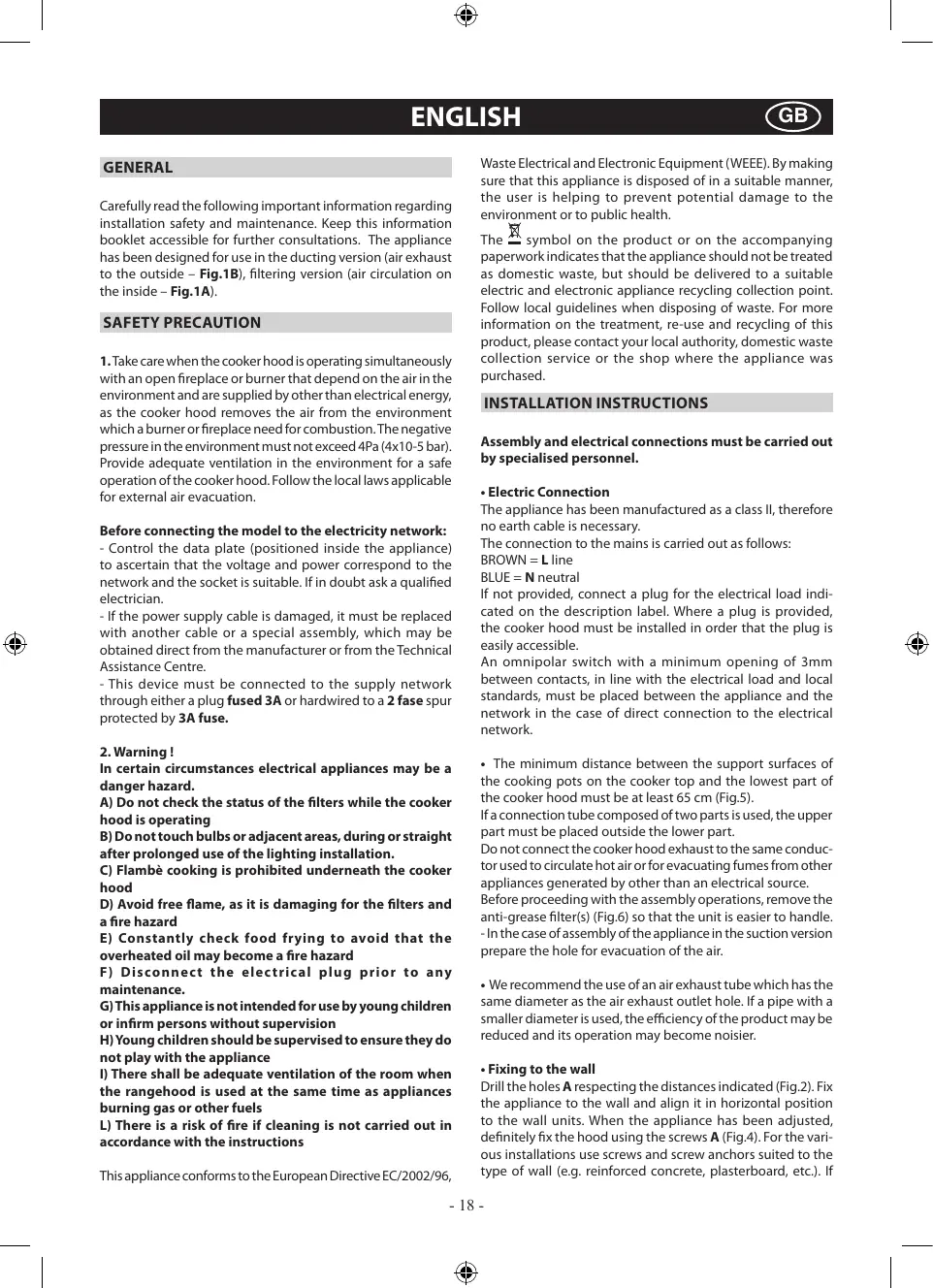
Carefully read the following important information regarding installation safety and maintenance. Keep this information booklet accessible for further consultations. The appliance has been designed for use in the ducting version (air exhaust to the outside - Fig.1B), filtering version (air circulation on the inside - Fig.1A).
SAFETY PRECAUTION
- Take care when the cooker hood is operating simultaneously with an open fireplace or burner that depend on the air in the environment and are supplied by other than electrical energy, as the cooker hood removes the air from the environment which a burner or fireplace need for combustion. The negative pressure in the environment must not exceed 4Pa (4x10⁻⁵ bar). Provide adequate ventilation in the environment for a safe operation of the cooker hood. Follow the local laws applicable for external air evacuation.
Before connecting the model to the electricity network:
- Control the data plate (positioned inside the appliance) to ascertain that the voltage and power correspond to the network and the socket is suitable. If in doubt ask a qualified electrician.
- If the power supply cable is damaged, it must be replaced with another cable or a special assembly, which may be obtained direct from the manufacturer or from the Technical Assistance Centre.
- This device must be connected to the supply network through either a plug fused 3A or hardwired to a 2 fase spur protected by 3A fuse.
2. Warning!
In certain circumstances electrical appliances may be a danger hazard.
A) Do not check the status of the filters while the cooker hood is operating
B) Do not touch bulbs or adjacent areas, during or straight after prolonged use of the lighting installation.
C) Flambé cooking is prohibited underneath the cooker hood
D) Avoid free flame, as it is damaging for the filters and a fire hazard
E) Constantly check food frying to avoid that the overheated oil may become a fire hazard
F) Disconnect the electrical plug prior to any maintenance.
G) This appliance is not intended for use by young children or infirm persons without supervision
H) Young children should be supervised to ensure they do not play with the appliance
1) There shall be adequate ventilation of the room when the rangehood is used at the same time as appliances burning gas or other fuels
L) There is a risk of fire if cleaning is not carried out in accordance with the instructions
This appliance conforms to the European Directive EC/2002/96,
Waste Electrical and Electronic Equipment (WEEE). By making sure that this appliance is disposed of in a suitable manner, the user is helping to prevent potential damage to the environment or to public health.
The symbol on the product or on the accompanying paperwork indicates that the appliance should not be treated as domestic waste, but should be delivered to a suitable electric and electronic appliance recycling collection point. Follow local guidelines when disposing of waste. For more information on the treatment, re-use and recycling of this product, please contact your local authority, domestic waste collection service or the shop where the appliance was purchased.
INSTALLATION INSTRUCTIONS
Assembly and electrical connections must be carried out by specialised personnel.
Electric Connection
The appliance has been manufactured as a class II, therefore no earth cable is necessary.
The connection to the mains is carried out as follows:
BROWN = L line
BLUE = N neutral
If not provided, connect a plug for the electrical load indicated on the description label. Where a plug is provided, the cooker hood must be installed in order that the plug is easily accessible.
An omnipolar switch with a minimum opening of 3mm between contacts, in line with the electrical load and local standards, must be placed between the appliance and the network in the case of direct connection to the electrical network.
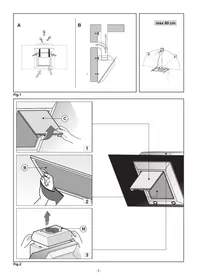
- The minimum distance between the support surfaces of the cooking pots on the cooker top and the lowest part of the cooker hood must be at least 65~cm (Fig.5).
If a connection tube composed of two parts is used, the upper part must be placed outside the lower part.
Do not connect the cooker hood exhaust to the same conductor used to circulate hot air or for evacuating fumes from other appliances generated by other than an electrical source.
Before proceeding with the assembly operations, remove the anti-grease filter(s) (Fig.6) so that the unit is easier to handle.
-
In the case of assembly of the appliance in the suction version prepare the hole for evacuation of the air.
-
We recommend the use of an air exhaust tube which has the same diameter as the air exhaust outlet hole. If a pipe with a smaller diameter is used, the efficiency of the product may be reduced and its operation may become noisier.
Fixing to the wall
Drill the holes A respecting the distances indicated (Fig.2). Fix the appliance to the wall and align it in horizontal position to the wall units. When the appliance has been adjusted, definitely fix the hood using the screws A (Fig.4). For the various installations use screws and screw anchors suited to the type of wall (e.g. reinforced concrete, plasterboard, etc.). If
the screws and screw anchors are provided with the product, check that they are suitable for the type of wall on which the hood is to be fixed.
- Fixing the decorative telescopic flue - extractor version Arrange the electrical power supply within the dimensions of the decorative flue. If your appliance must be installed as an extractor version, make sure an air exhaust hole has been prepared. Adjust the width of the support bracket of the upper flue (Fig.3).
Then fix it to the ceiling using the screws A (Fig.3) in such a way that it is in line with your hood and respecting the distance from the ceiling indicated in Fig.2. Connect the flange C to the air exhaust hole using a connection pipe (Fig.4). Insert the upper flue into the lower flue. Fix the lower flue to the hood using the screws B provided (Fig.4), extract the upper flue up to the bracket and fix it with the screws B (Fig.3). To transform the hood from a ducting version into a filtering version, ask your dealer for the charcoal filters and follow the installation instructions.
- Filtering version
Install the hood and the two flues as described in the paragraph for installation of the hood in ducting version. To assemble the filtering flue refer to the instructions contained in the kit.
The charcoal filters are already fitted to the appliance (Fig.7).
USE AND MAINTENANCE
- We recommend that the cooker hood is switched on before any food is cooked.
We also recommend that the appliance is left running for 15 minutes after the food is cooked, in order to thoroughly eliminate all contaminated air.
The effective performance of the cooker hood depends on constant maintenance; the anti-grease filter and the active carbon filter both require special attention.
- The anti-grease filter is used to trap any grease particles suspended in the air, therefore is subject to saturation (the time it takes for the filter to become saturated depends on the way in which the appliance is used).
-To prevent potential fire hazards, the anti-grease filters should be washed a minimum of every 2 months (it is possible to use the dishwasher for this task).
- After a few washes, the colour of the filters may change. This does not mean they have to be replaced.
If the replacement and washing instructions are not followed, the anti-grease filters may present a fire hazard.
- The active carbon filters are used to purify the air which is released back into the room.
The filters are not washable or re-usable and must be replaced at least once every four months.
The active carbon filter saturation level depends on the frequency with which the appliance is used, the type of cooking performed and the regularity with which the anti-grease filters are cleaned.
-
Clean the cooker hood frequently, both inside and outside, using a cloth which has been dampened with denatured alcohol or neutral, non-abrasive liquid detergents.
-
The light on the cooker hood is designed for use during cooking and not for general room illumination.
Extended use of the light reduces the average duration of the bulb.
Commands: (Fig.8)
Push-button A = on/off lights switch
Push-button B = on/off cooker hood switch. The appliance switches on at speed level 1, If the cooker hood is on depress the push-button for 2 sec. to switch off the cooker hood. If the cooker hood is at speed level 1 it will not be necessary to depress the push-button to switch the cooker hood off. Decreases the motor speed.
Display C = indicates the motor speed level selected and activates the timer.
Push-button D = switches on the cooker hood. Increases the motor speed. Touching the key at 3rd speed, the intensive function runs for 10^ then the appliance goes back to work at the original speed. During this function the display blinks.
Key E = The Timer times the functions on activation for 15 minutes, after which they are switched off. The Timer is deactivated by re-pressing Key E. When the Timer is activated the decimal point must flash on the display.
The "clean air" function is activated by pressing key E for 2 seconds when the appliance is switched off. This switches the motor on for 10 minutes every hour at the first speed. During functioning a rotary movement of the peripheral segments must be visualised on the display. When this time has passed the motor switches off and the fixed letter "C" must be visualised on the display until the motor re-starts after 50 minutes for another 10 minutes and so on. Press any key apart from the light keys to return to normal functioning. Press key E to deactivate the function.
- Active carbon/grease filter saturation:
-
When display item C flashes, at a speed where it alternates with the letter F (e.g. 1 and F), the grease filters must be washed.
-
When display item C flashes, at a speed where it alternates with the letter A (e.g. 1 and A), the carbon filters must be replaced.
After the clean filter has been positioned correctly, the electronic memory must be reset by pressing button A for approximately 5 seconds, until the indication F or A shown on the display C stops flashing.
- Commands: (fig.9 A) luminous the key symbols are explained below:
A = LIGHT
B = OFF
C=SPPEEDI
D = SPEED II
E = SPEED III
F = AUTOMATIC STOP TIMER - 15 minutes
- By pressing key F for two seconds (with the hood switched off) the "clean air" function is activated.
This function switches the appliance on for ten minutes every hour at the first speed.
As soon as this function is activated the motor starts up at the first speed for ten minutes, During this time key F and key C must flash at the same time.
After ten minutes the motor switches off and the LED of key F remains switched on with a fixed light until the motor starts up again at the first speed after fifty minutes and keys F and C start to flash again for ten minutes and so on.
By pressing any key for the exclusion of the hood light the hood will return immediately to its normal functioning (e.g.
if key D is pressed the "clean air" function is deactivated and the motor moves to the 2nd speed straight away. By pressing key B the function is deactivated).
- Active carbon/grease filter saturation:
-
When button A flashes at a frequency of 2 seconds, the grease filters must be cleaned.
-
When button A flashes at a frequency of 0.5 seconds, the carbon filters must be replaced.
After the clean filter has been replaced, the electronic memory must be reset by pressing button A for approximately 5 seconds, until the light on the button stops flashing.
- Commands: (fig.9 B) mechanical the key symbols are explained below:
A = LIGHT
B = OFF
C=SPPEEDI
D = SPEED II
E = SPEED III
G = MOTOR WORKING indicator
- Replacing halogen light bulbs (Fig. 10).
To replace the halogen light bulbs B, remove the glass pane C using a lever action on the relevant cracks.
Replace the bulbs with new ones of the same type.
Caution: do not touch the light bulb with bare hands.
- Replacing incandescent light bulbs (Fig. 11).
To remove the incandescent light bulb, take out the grease filters as described in (Fig. 6) and remove the bulb.
Replace it with a new one of the same type (Fig. 11).
CUSTOMER ASSISTANCE SERVICE
Before contacting the Technical Assistance Service:
If the product does not operate at all, we advise you to:
- check that the plug has been inserted into the power socket correctly.
If you cannot identify the cause of the operating anomaly: switch off the appliance (do not subject it to rough treatment) and contact the Assistance Service.
PRODUCT SERIAL NUMBER. Where can I find it?
It is important that you inform the Assistance Service of your product code and its serial number (a 16-character code which begins with the number 3); this can be found on the guarantee certificate or on the data plate located inside the appliance.
This will help to avoid wasted journeys being made by technicians, thereby (and most significantly) saving the corresponding callout charges.
THE MANUFACTURER DECLINES ALL RESPONSIBILITY FOR EVENTUAL DAMAGES CAUSED BY BREACHING THE ABOVE WARNINGS.

ALGEMEEN
INSTALLATIE INSTRUCTIES
C = knop EERSTE SNELHEID
D = knopTWEEDWERDESNELHEID
E = knop DERDE SNELHEID
F = knop TIMER AUTOMATISCHE ONDERBREKING na 15 minutes
C = knop EERSTE SNELHEID
D = knop TWEDW DERDE SNELHEID
E = knop DERDESNELHEID
G = controlampje WERKENDE MOTOR
POVELY: (Obr.9 A) Svetelne
A = tasting for BELYSNING
B = tast for OFF
C = tast for FØRSTE HASTIGHED
D = tasting for ANDEN HASTIGHED
E = tasting for TREDJE HASTIGHED
F = tast for TIMER AUTOMATISK STOP 15 minutter
A = tast for BELYSNING
B = tast for OFF (AV)
C = tast for FØRSTE HASTIGHT
D = tast for ANNEN HASTIGHET
E = tast for TREDJE HASTIGHET
F = tast TIDSURE AUTOMATISK STOPP 15 minutter
A = tast for BELYSNING
B = tasting for OFF (AV)
C = tast for FØRSTE HASTIGHET
D = tast for ANNEN HASTIGHET
E = tast for TREDJE HASTIGHET
G = kontrollampe for MOTOR I FUNKSJON
$$ M A R O = L f a z \check {a} $$
$$ \text {B L E U M A R I N} = \mathbf {N} \text {n e u t r u} $$
Este necessar sà dispuneti de o prizā separata, la norma, pentru a putea suporta sarcina indicată pe eticheta cu caracteristi. Daca ati prevázut o astfel de prizā, avei grijña sá fie amplasata intr-o zona uşor accesibla sú dupa montag.
m = 311
m = 311
e
n
2
i
e
1
。
+
1
1
三
A
m = 311 ;
OBUHECBUNDEHNA
BHNMaTeIbHo IpoOHTaIte CoDEpKaHne daHHoIN HNCTpyKUIM, NOCKOBky COePjNt BaxKbIe yka3aHIn, OTHOCJmec K 6E3OpAChOCTnYCTAHOBKn, EKcPiyatauIN nTexO6CnyKuBAHIn. CoxpanHe INCTpyKUINOJIaIOBIO daJIbHeNeiwe KOHCyIbTaUN. YcTPOINCTBO pArbaOtoBaHO CNeDyUoiX BApnaHTax NCONLHeHIN: BbITaIXHoe YcTPOINCTBO (ydaIeHne BO3dyxA n3 NOMeUeH - PNC.1B),ΦNbIbTpryOUIee YcTPOINCTBO (peuPKyIaIure BO3dyxA BHyTPn NOMeUeH - PNC.1A).
MEPbI PEPDOCTOPOXOCTN
- 5bIbB HBMAteBbHbIM, ecnO ndHOpeMeHHo pa6oTaET BbTJkN I rOpEnKa Nm OUar, HxKJIOUmeC B OKpyKaIOUeM BO3dyXe N 3aNNtBbAIOUeCn HNO JHEpRnei, Kpome 3NeKTPnueckoB TAKOM Cnyae BbTJkKa ydaJIaET n3 NOMeHHeN BO3dyX, HxKbI dI pypoecca cropaHnB RopEnKe nn Oyare.
OtpncaIbHoe daBneHne B nOmeeHn He doJNHO ppeBbIaTb 4Pa (4× 10^-5 bar).ДЯн HDexHNO i6eONaCHO pa6ObTu cNeDyET o6ecneuHT bENTnIaCIO nOmeueHn.ДЯн hapxNbIX bIb6pocOB cObIaDaT bpAina, DeiCTbYIOue B Bauei CTpaHe.
Ipexe yem noeknouhtb np6op K 3neKtpnucecko cetu:
-y6eintcbc B COOTBCTCBn Hnnpjxehn N MOUHOCTNpnbopa, daHbIe O KOTOpbIX NOMeIeHb I Ha 3aBOdCKoNnacnpTNO tabnue, ceTeBbIM noka3aTeJm, a TaKxpe COOTBCTBnE 3NeKTpOcoEoHNHTenr(po3EtKn).B cnyae HeCOOTBCTBnR po3eTKn o6paTnCB K KBaIIuΦniuPobAHOMy3NeKTpNKy.
- Ecnin npoBOD 3nEkpOnHAnH NOBpExJH, 3aMeHNte erO nnBec cneuNaHbY3eN pOn3BOnTeJIIN B yonlonHOUMOHcHOM cHeHpe TEXNHcKOrO 06CnyXBaHHa.
- IIOJcOeHHHb YcPOIcTBo K cTeH 3JIeKTOPIHnAHn HIOpeCTBOm IITREnceJIbHO BIIJK C npEdoxpaHHTeMe 3 A IIN DBYX DBYHXIOHOCBH XPOBOJc npEdoxpaHHTeMe 3 A.
2. Bhumahne!
B HeKOTOpbIX CnyaX 3NeKTpueckne np6Opbl MoryT 6bITb ONaChbIMN.
A) He npobepa Te coctoHne pnbTpoB npu pa6toUe BbITAAKKe
B) He npnkaiaTecb K naMnoUcKam I nn K npnneraoUoIM 3OHAM B npoucee pa60tbi CnCTembl OCBseuEHHI nn Cpasy Xe nocne ee BvkiuOeuHn
C)3aPpezaeTcraTOBNTb 6JIoJa ha OTKpbITOM pIaMeHn IOd KUxOHHO BbITJXKOI
D) N36eAitne otKpbItoro nIaMeHn, TAK KAK OHO nobpeXdaet fHbtpbIMoKet npBecTNI B03rOpahnO
E) B npouecce xkapkn BO pprHIOpe HnpepbIbHO cIeIInTe 3a npoueccom BO n36ekAHne BO3rOpaHne KINpIeero macna
F) OToeunHnIte WtencBHyU BnKy oT cTeBOI po3eKn npeed hauanom texhueckoro 6cbnyKbAHna
G)ИЗдени He paцитно Ha Экплуатаци ДетьMu ИИн He dedecnoc6bHIMI NIIaMn 6e3 KOHTpOJ.
H) He pa3pewaite detam irpaTb c n3dennem
I) Ecnn BbTjraKkna NcNpONb3yeTcOdHOBpeMeHNo cDpyrUmnpn6opamn, K bOTopBix nCOnb3yTec TOnnnBbHra3n nn DpyrHe BVdI TonPbBA, B NOMeUeHHoJXHa DoJXHa 6bItb06ecneHea HndnexaAaBentnua
L) B cnyae bblonHnna onepaun no qntke 6e3 co6IIOeHN Hnctpykun cyuectbyet onacnoctb BO3rOpanHa
JaHnOe N3dJIne IMeET MapKupOBky COOTBeTCTBnE BEponeckomy HopMaTbY 2002/96/EC, YtunN3aunna 3NeKTPnuecknx N3eKTPoHNbIX N3dEni (WEEE).IpObePbTe, TTO6bl NOOKOHAMIN erO cPoKa CnyXbbl DaHnOE N3dEnie 6blIO cDaHO BytNb. 3Tm Bbl NOMoxete CoxpaHntb OkpykaUOyUcpey.
Cnmbon Ha n3dennnn nn B npnaaraoocec K Hemy DOKymeHaauin O3Hauaet, YTO daHHoe n3dene He doNkHo paccMatpnbatcbKaK 6bITOBbe OTXOdb,a DOJHKHO 6bTb CdaHO B CteuaNBHy CEHTP yTNIN3aUN, 3aHMaHOuNcY HNYTOKeHEm 3eKTPnuEeCKNX u 3eKTPoHNbIX np6OpOB. U3dene DOJHX 6bITb CdaHO B yTNIB B COOTBeCTBUN C MeCTbIMN HOPMaTHBAMn PO yTNIN3aUN OTXODB. 3a DOJONIHNTelbHbIMN CBeDEHnMn KacaTeNbHO o6pa6OtKn, yTNIN3aUN n yHNUTOKeHn DaHORo n3dene o6paaiTeCb B MecTHOE OTdENHe Nc6opaDMaHInx 6bTOBix np6OpOB nIbn B Maraun, B KOTOPOM 6bJNo Kynlneho n3dene.
HCTPYKUNIPOYCTAHOBKE
Pnp6op nMeet Knacc II, no3tOMy K 3a3eMneHHe He ndo npDoceHNrTa HnKaKoI npOBd, npDoceHNHeHne
-ПиббОп IMeET KNaCxI, NOэТOMу KЗa3eMJIeHnI He NaO IOД coeДИнгЯнБИКАКОЛ рЮВОД, NOДСоeДИнCHENIE KЭЛeKТРсЕТи BByINOLHETcR cIeDyUOIM o6B30AM:
KOpuHHeBbI-L-ⅡHHN
CUNHIN-N-HeNTPaNHBII
Ecnn Ha Ka6beHet Wtencen, yctaHOBnTB Wtencenb, paccuHTaHHb H a pa60Ty C hargy3KoY, yka3AHHO H Ta 6bnue kxaapKTepncTcK. EbcBbTaJkckOa OchaueHa TcNcem, oha YCTaHABnBaetc, npu ycIOBAA, tO CTENcEb 6ytdeOCTynbM. B cnyae npmoro noCoedHHeN K 3JeKeTPOCETn HyxHo pa3MeCTnB mexdy np6Opom n ceTbMO MHOrONIOCHb BYIKIooATEnb C 3a3OpOM KOHTAKTOB MNHMYM 3 MM, paccuTaHHb H a HxHyU Hargy3Ky N OTBeaIOUIN DeIeCTByoUIM HOPMaM.
-MinHmAbhAaNCTaHcIy Mekdy onOpHOr HargpeBaOuSeCn IIOCKoCTbIO N HIXKHe aCTbIO KXYOHHOro DbIMOCoca DoJHkHa 6bITb He Meebe 65cm (Cxema5).EclnPiPMHeaTcCoeHNHTenBHaar TpybU nDByx u BoJe euaTe,To BepHra TaCbT OAnKhA paONaratbCS ChaPyrKn HIXKeH qaCTn. He CoeHNrTa Bbl6poc n3 BblTjXKN C KaHAlON cNpKyIaUNI rOpyeRo BO3dyxA UIN C KaHAlON,NCNOLb3YeMbIM dNt OBda Dbima OT yctpoBt,3aNbITbBAeMbIX INHOJ 3hePrrne KpOME 3NeKtpueckoi.PepeTemKaKpiCTynbKc6OpkeYctpoiCTba,NdO6nerHeyero MOtJaXaOTcoeHNHTe FInbTp/ XkpoyNaBnBaioUni FInbTp (pnc.6).
B TOM Cnyuae, ecn npnbop MOHTnpyETc C BbITaJhbIM yCTpOCTBOM, peKOMEHdyETc OeCneYtB NOMEUHe
BbIBOДнБIM OTBepCTnEM.
- PekomeHnyetcNcNoNb3OBAbTtp6yDbIMoxoJa c TaKIM xe dIaAMetpOM, YTO n OTBepCTne Nocauu B03dyxa. NcNoB3OBAHnue CzyeHHOnTpy6bl MoKETcKOpaTnt KINDb bItraKnnu yBEnuHTbe ee WymoBOY yPObHeB.
PpKpeHne KcTeHe
BbIPOHnHTe OTBepCTN A, Co6IOJdA yka3aHHbIe pacCTOHHN (pnc.2).PnIKpeNTe UcTPOrCTBO K CTNe pnp nomoOn peyInpyemero kpoHtseHa, BbIPOBHnYe UcTPOrCTBO RROP3oHTaBbHom NonoKeHN. PnIKpeNTe OKOHaTeNbHO KOJIaNk DByMn BVHTAmn A (pnc.4).B 3abuCIMoCTn OT BapAnhta MOHTaJa NcNoB3yIte BnHTbI (UsyPbI) n IIO6eHN COOTBeCTByUOJne TINy CTeHbI (HanpImep, Jeene3o6etOH, INCOKAPOrTH n T. d.) EcnI BNHTbI n IIO6eHN BxOJrT B KOMnEKT NoCTaBKn, cJeDyET yOcTOBepNTbC B TOM, YTO OHN NOxODJ TnI TORO TINa CTeHbI, Ha KOTOpONdoJXeH bItb CMOHTPOBaH KOJInak.
MOnTak DeKopatBnBbIX TeNeckOInuYecknx c6Opouhbx 3JeMeHToB - BbITaRkCa COTBoDM B aTMocΦepy
IpeBapInTeNbHO BbInOJIHnTE NOBDOkY 3JIeKTPoNpOBoD OB HByTn DEKOPATNBHO C6OpOHOrO 3JEMeHTa. EcnI Ba7a BbITXKa pa6Otaet B OTBOHOM pexHmE, Heo6xOdMIO NOI-ROBOTb OTBepCTne DblMOydaENH. OtperyuPyte WnpHy NopDePExKBAUeTO KPOHsTeHa BepxHero C6OpOHOrO 3JEMeHTa (pmc.3).
PnKpEnIte ero KnotOly BnHTaMn A TaK, YTO6bI oBcepeHtB erO COoCHoCT C BAAIM KOJNAkOM (pnc.3), co6NIOaAR paCtOHaHE NT oT ONTKa, yka3aHHoe Ha pnc.2. CoeINHtE fNaHeC C oTBepCTmE m N BbIEDeHn BO3dyxa NocpeDCTBM CoeINHtENbHO Tpy6bl (pnc.4).
BCTaBBTe BepxHn C6OpOHyb 3JIeMeHT B HnXnHn. PpIKpeNITe HnXnHn C6OpOHyb 3JIeMeHT K KOINaKy, INcONb3yA BNtBu B, KOTOpbIe PnpunaraIOcTc (Pnc.4), CmecTne BepxHn C6OpOHyb 3JIeMeHT Do KpOnuTeHa n PpIKpeNITe ero BNHTAMn B (Pnc.3).
Длп npeBpaueHnKoNkaka n3 BbITBXHO RБФиьТуOuшm 06patnteCb K CBOEMy DnIepy dЯн lonyeHnФИьТpoB c AKTiBnPoBaHbIM yrgem n CneDyTe INHCTpyKcUmaN m OycTaHOBke.
Kolnak B BapnaHte fNJIbTpUoJero yCtpoiCTBa
YctaHOBInTe KOpNk INDbC6OpOuHbIX 3JeMeHtA KaKyKa3aHO B pa3dEne NO C6OpKe KOpNk A BapNaHTe BByTJxHOrO YcTpoiCTBa.ДЯСбОКиФиЛТуРЮцERO 3JeMeHtA cIeDyIte NTHCTpyKUAMC,CoDEpZaUIMCMB KOMPnKTE pINHaIaNEXHoCTeYrOJIbHbIe FInlbTpbl yXe YCTaHOBJIeHb B BYTJxke Pnc.7).
3KcπyATAUry NTEXXOD
- Pekomehnyem BBeCTn annapat B kCcnIpyaTuHIO, npexJe cHmnpCTynatb K Bapke KaKoro-Jn6o 3neMeHNTa. PeKomehnyem octabntb pa60TaB annapat Ha 15 MmHyT, noCte 3aBepuHnna pIriOTOBHeHHn NIIuN, TTObI nOJIHOCTbIO BblNyCTNb TjKeJbI BO3dYx.
XopoOoee NyKUHOHnOBaHne KOJnaka OobcNoBHeNO npabNbHbIM IN oTOCHnHBbM TEXHuYeCKM O6CnyXnBaHnEM;OCO6oe BHNMaHMe CNeDyEt yDeJIbTb FInbTp Jxnpa N aKTbVnPoBaHnHO YrIe.
Фильст ровети Краа 3джрпьагт Лкньчы acntubl, haxoiauieceB a BoDyue, cneodobateNbHO, onbodberpaetcaT 3aCopeHnBmR a P3aHbYe npomexkTuK bPemehi, b3AvisNMOCTO
OT NcNoB3OBAHnA aNapaTa.
- TTo6bI npEynpeiNtB onaChOCTb BO3MOXhBx Bo3RopAHH, MaKcUIMy KAnZble 2 MecuJa Heo6XoHmIO npOMbIBaTb FnNbTbI npOTIN Jxnpa, da Yero MOxHO TaKxe IcNoJIb3OBAbT NOCyDOMOEHYIO MAuHNy.
-Послne ррмьан,在Mожно поровпь Изменицета. 3To He daet npaba Na прдявенип рпетени дг похВОзМСКHOДЗAMEHЛ.
B Cnyuae HeBbIpoJIneHnI INCTpyKUmI NO 3aMeH e I npOmbaHIO, MOKeT NoRbITcR pNCK Bo3ropaHnI ΦIbTpRoB npOTIB Kna.
ΦNlbTpbl cakTNBupoBaHbIM yIyIeM CnyKAT IJN OUcTKn B03dyxa OKpyKaIOuIe CpeIb. ΦINbTpbl MOxHO IpOMoBtBn INI INCNOJIb3OBaTb NOBTOPH, HeO6XoDIMO 3aMeHrTB NIX MaKcUMym pa3 BVeIbe MeCzua. HAcbIeHHOCt b AKTNBupoBAHHorO yIgN 3aBNCNT O CTNIJKOM dINITeNbHORO INCNoJIb3OBAHnA pnnapata, OT TINa KUYHXN IN pErYIaRpHOCTn POBeDEHnO uCNKnΦINbTpa npOTNB XIPA
- Heo6xodIMMo qactO OUYMaTb KOnnak KAK BHyTpN, TaK IN ChAPyJNs, NcPONlb3yB yBNAJXHeHHYo DeHaTyPnPoBaHHbIM CnIPrTOm TKAHb NIN HNeTpaJIbHbIe He cuaPaNaIoUe JxNdkne MOIOuIe CpeDCTBA.
- lamnbl bblTgKKn cnykat dny ocBeueHn BapouHno nane Hb BO BPMe npriTOBJIeHNu Ine paCHTaHbI Ha dnntelbHoe BKNIOUeHNy dny obuHoro OCbeueHn NOMEeHNu. PpOdoJNkTeJIbHOcNPOHb3OBAHme NaMn bblTayKeK 3NaHTeJIbHO cOKpaauet INx CpeHNh cPOK cnyk6bl.
OprahbyynpaBneHn:(Pnc.8)
KnaBnuaA=BkIIOuAe/TBbIKIOuAeT NOCBETky
KnaBmua B = BKIOUeHHe/BbIKIOUeHHe BbITXKKn. BbITXKkBAKIOUaETcHa 1-0nCKOpOCTn. EcnBbITXKkBAKIOUeHa, HAXMITE KHOKNy Ha 2 cekYHdbI, YTO6bI BbIKIOUHTb ee. EcnBbITXKa pa6Otaet Ha 1-0n CkOpOCTn, He HxKHO depXkaTb KHOKNy HaxatoJnIe ee BbIKIOUeHn. CkOpOCTb DnIRateJIe COKPauaETcN.
Дисп徴 C = NOKa3bIbAeT CKOpOCTb MOTOPa, KOTOPa 6blJa Na6paHa, И ВКЛIOUeHne TaMepa.
KnaBnuaD=BkJIIOaEt BbITaIKy.YBeINuBaET CKOPOCTb MO-Topa.Haxatme KnaBun3-3-KCPOCTN Bbl3bBAET AKTUBAUHO ΦHKUHNHTECNBHOROpexIMHa 10 MN, NO IcTceEHIN KOtOBx BOCCTaHaBnIBaTcA CKOPTb pa60Tb,AKTNBHO MOMeHTBKUOnEHHaDHHOfYHKUN. Ha nepiOd JeIcTBn UHTEHCNBHORo pEXIMHa IMeT MeCTo MOrTaHne INHdNKATOpA.
Knabuha E = TaIeMep Ha 15 MNHyT 3aIOMnHaet fhyHKcH N B MOMENT BKIOUeHnA NOCNE OTKIOUeHnE TINX fhyHKnN. TaIeMep OTKIOHaeTc NOBTOPbHM HaaATmEh KONKn E. Korda fhyHKnra TaIeMep BKIOUeHa, Ha dncPiee DoJNHO MIRaTb DEcaTNUHoe 3NaueHne.
Haxaab KhoNky E ha 2 cekyHdbi npn BbIKIOueHHoBbITaKke, BKNIOaETcra YHKUJIa «MCTbI BO3dYx, 3Ta yHKUJIa BKNIOaET dBIRATEb Ha 1-Oi cKOPOCTn Ha 10 MNHT kKaJbI aC. Bnpoucece YHKUINHOpOBAHnHa dncPnee NOKa3bIAHOTcBApaiaOuIe6 bokOBBe cerMeTbI. INo nCTeueHN 3TOrO BVPemEH DBIRATEb BKBIOUaTeC, nHa dncPnee NOBIAETcBAkBa «C» Do cLeyIOeero 3aNycka DBIRATeHa 10 MNHT no npoeCTBm 50 MNHT.
3acopene HnIbTPOB-kuPoyNoBteNe / nIbTpcaKtNBupoBaHHbIM yrlem:
-KorgaHaDnCnnee Cnonepemehno Mmraot 3nauehne pa6ooye ckopocny 6kyBa F (Hanpim,1 n F) Heo6xOJMO BbMlbTbФnIbTpbl-KupoyNouBttn.
-KoJa dHaJcNpnee C nonepemeHNO mraOT 3haueHne pa6ohyckopocn6uKb4a (HaNPm,1nA) Heo6xoDnmo 3aMeHNt bIbnptbC aKnBnPobAHbHm yfNm.
Tocne yctahOBKnФnltpaHaMeCTO nocLe YnCTKN Heo6xoJIMo 06hynIb TNEkTPOHHy NamaTb, Haxab KHONky A npimpeHO Ha5 cek. BnIObToD nppeKpaueHn MrgaHn86ykbbl FnnlA ha nciPee C.
OprahbI ynpablenHm: (pnc.9 A) CBeTaeJeceC.
A=KHONKaOCBeUeHnA
B=KHONKa HnyeBOI
C=KHOJIa nepBOI CKOPOCTN
D=KHONKa BTOPOI CKOPOCTN
E=KHONKa TpeTei Ckopoctn
F = KHOIIKa TaIMepa aBTOMaTNUeCKoN OCTaHOBKn Uepe3 15 MHH
-HaKATOM nOJooHEn B TeueHne 2-x cKeYnD KnaBnUy F.ДЯ BKIOUeHnФyHKuIN "clean air" HauKaTb N epKxab T b TakOM noJooHEn KNaBnUy F.3TaФyHKcI IN EgeAcho BCJIIOuaET dBIRatTeBb Ha nepBockOpCtHa 10 MmHT, B TEueHne KOtobpIx DOJIKHbMnraTb OndOBpeMeHHO yka3aTeNl KNaBnUf N C. Pocne yero DBrarateBb BYkIOuAetaTc, a yka3aTeNb Ha kNaBnIe F OCTaetca 3AAKHeHHbIM. PIn6Ibn3ntEbnHO uePe3 50 MNHT ONrBa B KNUOaTEcTB DBrarateBb Ha nepBockOpCTN, yka3aTeN I F NCahNuHaOT mRaTb B TeueHne 10 MNHT u T.D.
Hakatmem IIO60 KnabNbIb, 3a NcKIOUeHEm KnaBnbl BKNIOUeHnO CBOEueHn, DbIMOCOC BO3BaPaAeTCB CBOE HopMJIbHOe paOooe COToTHe (HaNP, eCN HAKaTb KNaBNyD-OTKIOUaETc FyHKu"clean air" n DBrAtelb cpa3y Xe BKIOUaetCn Ha 2o ckOpCTn; HAKaB KNABbUy B FyHKuN OTKIOUaETc).
3acopenehe fHbTPOB-xynpoyNoBtenei / fHbTpcaKTNBupOBaHHbIM yIeM:
-Korda Mmraet KHONika A cachtoTOn 2 cek, Heo6xOIMO BblMbItb fNtbpI-kuPoyNoBHTenn.
-Korda Miraet KhoNka A c hactoto0 0,5 cek., Heo6xOJIMO 3aMeHntb fIbtpbI cAKTMBuPObaHHbIM yrlem.
Iocne yctahOBKn Ha MeTo cNcTOro 0nNbTa Pa Heo6xOaMo 0bHyntb 3JeKtPoHnyu nAmrTb, Haxab KOnkPy A npimepHo Ha 5 Cek. BnIoTb do pKePaueHnna MmraHn.
- OpraHbI ynpaBJeHn: (Pnc.9 B) MexaHnueckne
A=KHONKaOCBeUeHnA
B=KHONKa HnyeBOI
C=KHONKa nepBOB CKOPOCTN
D=KHONKa BTOPOI CKOPOCTN
E=KHONKa TpeTei CkopoocTN
G=JaMnoUka:ДВИГATEЛbВРБОЧEMPEЖUME
3aMeHa raJIoReHbIx lamn (Cxema 10).
ДяЗамены raLoReHnBix lamn B Chmnte CteKJIaHHyIO KpbIu-Ky C, noDЯБee OE TOBeTkoB B cneuaNbHbIX na3ax.
3aemeHHTeJaMnblHaJaMnblTAKOROKeTuna.
BhimaHne: He npikacaiTecb K lamnam rojblm pykaM.
- 3aMeHa lamn HakaJInBaHHa (Cxema 11).
Takm 6pa30 MoXHO n36ExaTh HnpaChoro Bbl3ObaTexHka, C3KOHOMIB Ha CTOnMOCTn O6CJyXuBaHna.
ΦMNA HE HECET HUKAKOJ OTBETCTBEHHOCTN 3A UJEPE, BbI3BAHHBJ HECOBJIIODEHEM BblIeTIPIBE- DEHHBX I PENEYIPKDEHIN.
OBSERVERA
C = knapp FÖRSTA HASTIGHET
D = knapp ANDRA HASTIGHET
E = knapp TREDJE HASTIGHT
G = kontrollampa MOTORN I FUNKTION
- Byta halogenlampor (Fig. 10).
- SAFETY PRECAUTION
- Before connecting the model to the electricity network:
- Warning!
- INSTALLATION INSTRUCTIONS
- Assembly and electrical connections must be carried out by specialised personnel.
- Electric Connection
- Fixing to the wall
- - Filtering version
- USE AND MAINTENANCE
- Commands: (Fig.8)
- - Active carbon/grease filter saturation:
- - Replacing halogen light bulbs (Fig. 10).
- - Replacing incandescent light bulbs (Fig. 11).
- CUSTOMER ASSISTANCE SERVICE
- PRODUCT SERIAL NUMBER. Where can I find it?
- THE MANUFACTURER DECLINES ALL RESPONSIBILITY FOR EVENTUAL DAMAGES CAUSED BY BREACHING THE ABOVE WARNINGS.
- ALGEMEEN
- INSTALLATIE INSTRUCTIES
- POVELY: (Obr.9 A) Svetelne
- OBUHECBUNDEHNA
- MEPbI PEPDOCTOPOXOCTN
- Ipexe yem noeknouhtb np6op K 3neKtpnucecko cetu:
- Bhumahne!
- B HeKOTOpbIX CnyaX 3NeKTpueckne np6Opbl MoryT 6bITb ONaChbIMN.
- HCTPYKUNIPOYCTAHOBKE
- Pnp6op nMeet Knacc II, no3tOMy K 3a3eMneHHe He ndo npDoceHNrTa HnKaKoI npOBd, npDoceHNHeHne
- PpKpeHne KcTeHe
- MOnTak DeKopatBnBbIX TeNeckOInuYecknx c6Opouhbx 3JeMeHToB - BbITaRkCa COTBoDM B aTMocΦepy
- Kolnak B BapnaHte fNJIbTpUoJero yCtpoiCTBa
- 3KcπyATAUry NTEXXOD
- OprahbyynpaBneHn:(Pnc.8)
- OprahbI ynpablenHm: (pnc.9 A) CBeTaeJeceC.
- 3acopenehe fHbTPOB-xynpoyNoBtenei / fHbTpcaKTNBupOBaHHbIM yIeM:
- - OpraHbI ynpaBJeHn: (Pnc.9 B) MexaHnueckne
- 3aMeHa raJIoReHbIx lamn (Cxema 10).
- - 3aMeHa lamn HakaJInBaHHa (Cxema 11).
- ΦMNA HE HECET HUKAKOJ OTBETCTBEHHOCTN 3A UJEPE, BbI3BAHHBJ HECOBJIIODEHEM BblIeTIPIBE- DEHHBX I PENEYIPKDEHIN.
- OBSERVERA
Brand : ROSIERES
Model : RBS9485IN
Category : Range hood