
BasicAir 250 - Compressor METABO - Free user manual and instructions
Find the device manual for free BasicAir 250 METABO in PDF.


| Product type | Portable air compressor |
| Brand | Metabo |
| Model | BasicAir 250 |
| Compressor type | Oil-free |
| Tank capacity | 6 liters (steel) |
| Maximum pressure | 8 bar (116 psi) |
| Air flow | 150 L/min |
| Motor power | 1.5 HP (1100 W) |
| Power supply | 230 V ~ 50 Hz |
| Dimensions (L x W x H) | 35 x 30 x 30 cm |
| Weight | 10 kg |
| Noise level | 85 dB(A) |
| Recommended use | Inflation, light spraying, cleaning |
| Safety valve | Yes |
| Pressure gauge | Yes (tank pressure) |
| Condensation drain | Yes (drain valve) |
| Air filter | Yes, washable |
| Automatic shut-off (pressure switch) | Yes |
| Thermal protection | Yes |
| Power cord length | 1.5 m |
| Spare parts available | Repair kit, seals, check valve |
| Routine maintenance | Filter cleaning, daily draining |
| Warranty | 2 years |
Frequently Asked Questions - BasicAir 250 METABO
User questions about BasicAir 250 METABO
0 question about this device. Answer the ones you know or ask your own.
Ask a new question about this device
Download the instructions for your Compressor in PDF format for free! Find your manual BasicAir 250 - METABO and take your electronic device back in hand. On this page are published all the documents necessary for the use of your device. BasicAir 250 by METABO.
USER MANUAL BasicAir 250 METABO
natural_image
Technical line drawings of two different types of air conditioners (no text or symbols present)
ENG Original operating instructions....9
natural_image
Technical diagram of a pressure regulator with two gauges and a valve, labeled with number 36 (no text or symbols beyond label)PowerAir 350

natural_image
Technical line drawing of a mechanical component with no visible text or symbolsnatural_image
Mechanical assembly diagram showing a pulley, screw, and shaft components (no text or labels)natural_image
Mechanical component diagram showing a cylindrical assembly with a bracket and two diagonal lines labeled 41 (no text or symbols on the component itself)5.2 Aufstellung
natural_image
Mechanical component diagram showing a cylindrical assembly with a base and connecting lines (no text or symbols)1 Outlet pressure gauge
2 Transport handle
3 Pressure regulator
4 Tank pressure gauge
5 Air filter housing
6 Dip stick
7 Compressor pump
8 Oil drain plug
9 Pressure vessel
10 Ball valve on condensate drain
11 Safety valve
12 Compressed air connection (quick-release coupling), regulated compressed air
13 On/Off switch
Table of Contents
-
Component Overview / Standard Delivery .... 9
-
EC Declaration of Conformity.... 10
-
Please Read First!...... 10
-
Safety ......10
4.1 Specified conditions of use ..... 10
4.2 General safety instructions ..... 10
4.3 Symbols on the machine ..... 11
4.4 Safety devices ......12
- Operation.... 12
5.1 Prior to initial operation .....12
5.2 Installation....12
5.3 Mains connection....12
5.4 Generating compressed air ..... 13
- Care and Maintenance...... 13
6.1 Periodic maintenance .....13
6.2 Machine storage .....13
-
Trouble Shooting .....14
-
Repairs......14
-
Environmental Protection ..... 14
-
Technical specifications ..... 15
2. EC Declaration of Conformity
We hereby declare that this machine complies with the basic requirements and provisions of the applicable directives.
3. Please Read First!
These operating instructions have been written so that you can quickly learn how to operate your device safely. Here is how to read the instructions:
- Read these instructions completely before use. Pay special attention to the safety information.
- These instructions are intended for persons with basic technical knowledge in the handling of machines such as the one described here. In-experienced persons are strongly advised to seek competent advice and guidance from an experienced person before operating this machine.
- Retain all documents delivered together with this device so that you and other users have access to the relevant information at all times. Re-
tain proof of purchase for any future warranty claims.
- If you lend or sell this device be sure to have these Operating Instructions go with it.
- The manufacturer is not liable for any damage arising from disregard of these instructions.
Information in these Operating Instructions is denoted as follows:
Danger!
Risk of personal injury or environmental damage.
Risk of electric shock!
Risk of personal injury by electric shock.
Caution!
Risk of material damage.
Note:
Additional information.
- Numbers in illustrations (1, 2, 3 etc.)
– denote component parts; - are consecutively numbered;
- relate to the corresponding number(s) in brackets (1), (2), (3) etc. in the neighbouring text.
– Numbered steps must carried out in sequence.
- Instructions which can be carried out in any sequence are indicated by a bullet point (•).
– Listings are preceded by a dash (−).
4. Safety
4.1 Specified conditions of use
This machine is designed to generate compressed air required for the operation of air tools. The machine should only be used under supervision.
Any use for medical purposes, food processing or filling of oxygen cylinders for breathing equipment is not permitted.
Gas or dust which is explosive, combustible or detrimental to health may not be compressed. Operation in explosive or dusty environments is prohibited.
Any other use is not as specified. Use not as specified, alteration of the machine or use of parts that are not approved by the equipment manufacturer can cause unforeseeable damage!
Children, juveniles and persons not instructed in use of this machine are not permitted to operate the machine or any air tools connected to it.
4.2 General safety instructions
- When using this electric tool observe the following safety instructions to exclude the risk of personal injury or material damage.
- Please also observe the special safety instructions in the respective chapters.
- Keep all documents supplied with the machine for future reference.
- Observe the statutory accident insurance institution guidelines and regulations for the prevention of accidents pertaining to the operation of air compressors and air tools where applicable.
- Observe the legal regulations regarding operation of systems subject to technical inspections.
- When operating and storing the machine be aware that leaking condensate and operating materials can contaminate the environment and lead to environmental damage.
General hazard!
- Keep your work area tidy – a messy work area invites accidents.
- Be alert. Know what you are doing. Set out to work with reason. Do not operate the electric tool while under the influence of drugs, alcohol or medication.
- Consider environmental conditions.
-
Keep work area well lighted.
-
Prevent adverse body positions. Ensure firm footing and keep your balance at all times.
- Do not operate the electric tool near inflammable liquids or gases.
- Keep bystanders, particularly children, out of the work area. Do not permit other persons to touch the tool or power cable while the electric tool is running.
- Do not overload the electric tool – use it only within the performance range it was designed for (see 'Technical Data').

Danger! Risk of electric
shock!
- Do not expose the electric tool to rain.
- Do not operate the electric tool in a damp or wet environment.
- Prevent body contact with earthed objects such as radiators, pipes, cooking stoves or refrigerators when operating this electric tool.
- Do not use the power cable for purposes it is not intended for.

Risk of personal injury by es-
caping compressed air and parts hurled about by escaping air!
- Never direct compressed air against persons or animals!
- Ensure all air tools and accessories used are designed for the working pressure or are supplied via a pressure regulator.
- Please note that when the quick coupler is disconnected the compressed air contained in the pressure hose will escape all of a sudden. You should therefore firmly hold the air hose when disconnecting it.
- Ensure all screwed connections are fully tightened at all times.
- Do not attempt to repair the device yourself! Only trained specialists are permitted to service or repair compressors, pressure vessels and air tools.

Hazard generated by lubricat-
ed compressed air!
- Use oil-saturated compressed air only for air tools requiring such supply.
- Do not use an air hose used to supply compressed air containing oil to supply air tools not designed for operation on compressed air containing oil.
- Do not fill tires with compressed air containing oil.

Risk of burns from the surfac-
es of parts carrying compressed air!
- Let tool cool off before servicing.

Risk of personal injury and
crushing by moving parts!
- Do not operate the compressor without installed guards.
- Please note that the compressor will start automatically when the pressure falls off to minimum! – Disconnect from power supply prior to any servicing.
- When turning ON the machine (e.g. after servicing) ensure that no tools or loose parts are left on or in the machine.

Hazard generated by insuffi-
cient personal protective equipment!
- Wear hearing protection.
- Wear safety glasses.
- Wear mask respirator when work generates dust or mist detrimental to health.
- Wear suitable work clothes. When working outdoors wearing of non-slip shoes is recommended.

Hazard generated by electric
tool defects!
- Keep electric tool and accessories in good repair. Observe the maintenance instructions.
- Prior to use check the electric tool for possible damage: before using the electric tool carefully check safety devices, protection devices and any slightly damaged parts for proper function as specified. Damaged machines must be properly repaired before use.
-
Check to see that all moving parts work properly and do not jam. All parts must be correctly installed and meet all conditions necessary for the proper operation of the electric tool.
-
Damaged protection devices or parts must be repaired or replaced by an authorised repair centre.
- Have damaged switches replaced by a customer service centre.
- Do not operate electric tool if the switch cannot be turned ON or OFF.
- Keep handles dry and free of oil and grease.
4.3 Symbols on the machine
Symbols on the machine


14 15 16 17 18

19
14 Read instructions.
15 Warning that personal injury may occur through touching of hot parts.
16 Wear safety goggles.
17 Warning against automatic startup.
18 Warning against dangerous voltage.
19 Guaranteed sound power level.
Information on nameplate:

20 Manufacturer
21 Article number, version number, serial number
22 Machi ne designation
23 Supply voltage / Frequency
24 Motor capacity P_1 (see also "Technical Specifications")
25 Power consumption / Protection rating
26 Motor speed / nominal output power
27 CE-mar k – This machine conforms to the EC Directives as per Declaration of Conformity
28 Date of manufacture
29 Suction capacity
30 Filling rate
31 Speed (compressor pump)
32 No. of cylinders
33 Maximum pressure
34 Volume of pressure vessel
35 Waste disposal symbol – Machine can be disposed of by returning it to the manufacturer
4.4 Safety devices
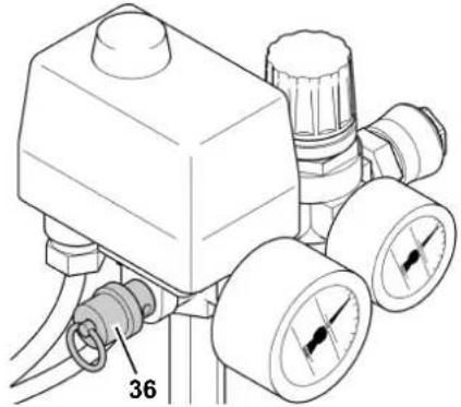
Safety valve
BasicAir 250/350
natural_image
Technical diagram of a pressure regulator with dual gauges and a labeled component (no text or symbols beyond the number 36)PowerAir 350

natural_image
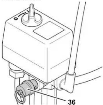
Technical line drawing of a mechanical component with no visible text or symbolsThe spring safety valve (36) is incorporated into the pressure switch unit. The safety valve opens if the max. permissible pressure is exceeded.
5. Operation
5.1 Prior to initial operation
Installing the wheels
• Install wheels as illustrated.

natural_image
Mechanical assembly diagram showing a pulley, screwdriver, and nut components (no text or labels)Insert dip stick
- Remove the plug (38) from the crankcase.

- Substitute the plug (37) with the dip stick supplied.
The plug prevents oil from leaking from the crankcase during shipping. Keep plug for future use.
Assembling the air filter
- Remove the plug from the air inlet of the compressor pump housing (39). Keep plug for future use.
BasicAir 250

BasicAir 350 and PowerAir 350
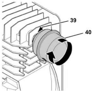
- Screw air filter (40) supplied on air intake.
Checking the condensate outlet
• Make sure the condensate outlet is closed (41).

natural_image
Mechanical component diagram showing a cylindrical assembly with a base and mounting bracket, intersected by two diagonal lines labeled 41 (no text or symbols on the component itself)5.2 Installation
The device's installation location must meet the following requirements:
• dry, cool, protected from frost
• firm, horizontal and level surface.

Severe accidents may arise due to incorrect installation.
- Secure the device against rolling away, tipping over and slipping.
- Do not pull the device by the hose or power supply cable. Transport the machine by the handle only.
- Safety devices and operating elements must be easily accessible at all times.
5.3 Mains connection
Danger! High voltage
Operate machine in dry environment only. Operate machine only on a power source complying with the following requirements:
- outlets properly installed, earthed and tested;
- fuse protection in accordance with the technical specifications.
Make sure that the mains cable is out of the way so that it does not interfere with the work and cannot be damaged.
Always check to see that the machine is switched OFF before plugging in.
Protect mains cable from heat, aggressive liquids and sharp edges.
Use only extension cables with sufficient lead cross section (see "Technical Specifications").
Do not stop the compressor by unplugging, but switch OFF using the switch.
Unplug after use.
5.4 Generating compressed air
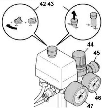
- Switch on the machine (42 or 43).
Wait until the maximum tank pressure is reached (the compressor shuts OFF).
The tank pressure is indicated on the tank pressure gauge (47).
BasicAir 250/350
PowerAir 350
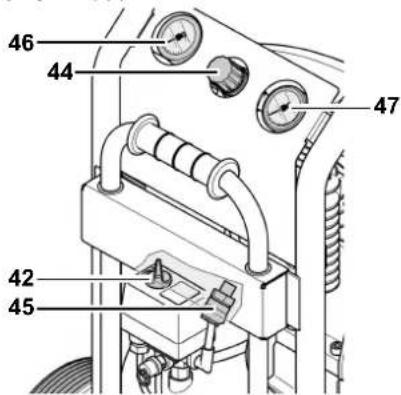
- Set pressure regulator (44) to required working pressure. The current working pressure is indicated on the regulated pressure gauge (46).

Caution!
The regulated pressure may not be set higher than the max. working pressure of the connected air tools!
- Connect air hose to compressed air outlet (45).
- Connect air tool. You are now ready to work with the air tool.
- Switch the compressor OFF, if you do not continue working immediately afterwards. Unplug after switching OFF.
natural_image
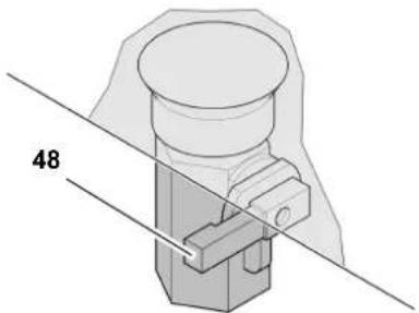
Mechanical assembly diagram showing a cylindrical component inserted into a housing, with two diagonal lines labeled 48 (no text or symbols on the component itself)- Drain the condensate from the pressure vessel once a day (48). To do this, tilt the machine slightly.
6. Care and Maintenance

Danger!
Prior to all servicing:
- Switch machine OFF.
- Unplug power cable.
- Wait until the compressor has come to a complete stop.
- Ensure the compressor and all air tools and accessories connected to it are relieved from pressure.
- Let the device and all air tools and accessories cool down.
After all servicing:
- Check to see that all safety devices are operational.
- Make sure that no tools or other parts remain on or in the machine.
Repair and maintenance work other than described in this section must only be carried out by qualified specialists.
6.1 Periodic maintenance

Caution!
On a new compressor pump, check the tightening torque of the cylinder head bolts (see 'Technical Data') after the first 50 and 250 hours of operation.
Prior to each use
- Check air hoses for damage, replace if necessary.
- Check all screwed connections for tightness and tighten if necessary.
- Check power supply cable for damage and have replaced by a qualified electrician if necessary.
Every 50 operating hours
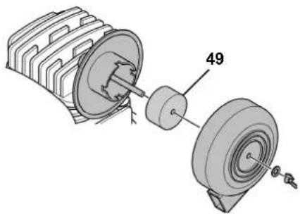
- Check air filter element (49) of compressor pump, clean if necessary.
natural_image
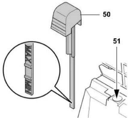
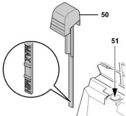
Technical illustration of a mechanical assembly showing a rotor and housing with labeled part 49 (no text or symbols beyond label)- Check the oil level in the compressor pump with the oil dip stick (50) and refill oil if necessary.(51)
Every 250 operating hours
- Replace air intake filter element of compressor pump.
Every 500 operating hours
- Drain oil and fill with fresh oil.
Every 1000 operating hours
- Have unit serviced by an authorized service station. This will extend the compressor's service life considerably.
6.2 Machine storage
- Switch unit OFF and unplug.
- Release pressure from tank and all connected air tools.
-
Drain condensate from pressure vessel.
-
Store device in such way that it cannot be started by unauthorised persons.
Caution!
Do not store or transport machine unprotected outdoors or in a damp environment.
Do not lay machine on its side for transport or storage.
7. Trouble Shooting
Danger!
Prior to all servicing:
- Switch machine OFF.
- Unplug power cable.
- Wait until the compressor has come to a complete stop.
- Ensure the compressor and all air tools and accessories connected to it are relieved from pressure.
- Let the device and all air tools and accessories cool down.
After all servicing:
– Check to see that all safety devices are operational.
- Make sure that no tools or other parts remain on or in the machine.
Compressor does not run:
- No mains voltage.
– check cables, plug, outlet and mains fuse. - Mains voltage too low.
– Use only extension cables with sufficient lead cross section (see
"Technical Specifications").
When the machine is cold avoid extension cables and relieve the pressure in the pressure vessel.
- Compressor was stopped by unplugging.
- Switch compressor OFF at the On/Off switch, then ON again.
- Motor has overheated, caused by insufficient cooling (cooling fins covered).
- First switch off the compressor using the ON/OFF switch and allow to cool.
- Eliminate the cause of overheating.
- Switch the compressor back on.
Compressor runs but does not build up sufficient pressure.
- Condensation water drain on pressure vessel leaky.
- Check the sealing of the outlet screw(s); replace if necessary.
- Tighten the outlet screw(s) hand-tight.
- Check valve leaky.
– Have check valve serviced by qualified service centre.
Air tool is not supplied with sufficient pressure.
- Pressure regulator not opened wide enough.
- Open pressure regulator more.
- Hose connection between compressor and air tool leaky.
- Check air hoses, replace defective parts if necessary.
Further work on the machine should only be carried out by a qualified electrician or the Service Centre in your country.
8. Repairs
Danger!
Repairs to electric tools must be carried out by qualified electricians only!
Electric tools in need of repair can be sent to the Service Centre in your country. See Spare Parts List for address.
Please attach a description of the fault to the power tool.
9. Environmental Protection
Danger!
The condensation water from the pressure vessel contains oil residues. Dispose of the condensation water in an environmentally-oriented manner at an appropriate collection point!
Danger!
Dispose of the waste oil from the compressor pump in an environmentally-oriented manner at an appropriate collection point!
The tool's packaging can be 100% recycled.
Worn out machines and accessories contain considerable amounts of valuable raw and plastic materials, which can be recycled.
These instructions are printed on paper produced with an elemental chlorine-free bleaching process.
- Technical specifications
| BasicAir 250 BasicAir 350 Power | Air 350 | |||
| Suction capacity l/min 240 290 | ||||
| Free air delivery (volume flow rate) l/min 120 150 | ||||
| Filling rate l/min 140 165 | ||||
| Max. operating pressure bar 8 10 | ||||
| Max. storage/operating temperature * °C + 40 | ||||
| Min. storage/operating temperature ** | °C | +5 | ||
| Pressure vessel volume | l | 24 | 50 | 23 |
| No. of air outlets | 1 | |||
| No. of cylinders | 1 | |||
| Cylinder head bolt driving torque | Nm | 10 | ||
| Speed | min-1 | 2850 | ||
| Motor capacity | kW | 1,5 | 1.8 | |
| Supply voltage (50 Hz) | V | 230 | ||
| Rated current | A | 7.2 | 7,9 | |
| Fuse protection min. | A | 10 time-lag | ||
| Degree of protection | IP 20 | |||
| Max. overall cable length with extension cables:– for 1.0mm2 conductor cross section– for 1.5mm2 conductor cross section– for 2.5mm2 conductor cross section | m m m | 101525 | ||
| Oil grade (pump) | SAE 40 (SAE 20) | |||
| Required oil quantity (pump) | l | approx. 0.25 | ||
| Dimensions: length × width × height | mm | 555 × 310 × 600 | 760 × 380 × 660 | 490 × 450 × 750 |
| Weight | kg | 28 | 33,5 | 37 |
| Max. sound pressure level LPA at 1 m | dB (A) | 87 + 3 | 89 + 3 | |
| Guaranteed sound power level LWA | dB (A) | 94 | 96 | |
| All technical specifications apply to an ambient temperature of 20°C. | ||||
| * The service life of some components, e.g. the check valve sealing, is substantially decreased when the compressor is used at high temperatures (max. storage/operating temperature and higher). | ||||
| ** At temperatures below the min. storage/operating temperature the danger exists that the condensate in the pressure vessel will freeze. | ||||
natural_image
Technical diagram of a pressure regulator with dual gauges and a labeled component (no text or symbols beyond the number 36)PowerAir 350

natural_image
Technical line drawing of a mechanical component with no visible text or symbolsnatural_image
Mechanical assembly diagram showing a pulley, washer, and nut components (no text or labels)natural_image
Technical diagram of a mechanical component with two intersecting lines and a labeled dimension '41' (no text or symbols beyond the label)5.2 Installation
natural_image
Mechanical component diagram with intersecting lines and labeled dimension '48' (no text or symbols beyond label)natural_image
Technical line drawing of a pressure regulator with dual gauges and a central housing (no text or symbols)PowerAir 350
natural_image
Technical line drawing of a mechanical component with no visible text or symbolsnatural_image
Mechanical assembly diagram showing a pulley, screw, and housing components (no text or labels)natural_image
Technical diagram of a mechanical component with a cylindrical housing and a bracket, intersected by two diagonal lines labeled 41 (no text or symbols beyond label)5.2 Installazione
natural_image
Mechanical assembly diagram showing a cylindrical component with a bracket and two diagonal lines labeled 48 (no text or symbols on the component itself)natural_image
Technical line drawing of a pressure regulator with dual gauges and a valve (no text or symbols)PowerAir 350

natural_image
Technical line drawing of a mechanical component with no visible text or symbolsnatural_image
Mechanical assembly diagram showing a pulley, washer, and nut components (no text or labels)Peilstok aanbrengen
natural_image
Mechanical component diagram showing a cylindrical assembly with a bracket and two diagonal lines labeled 41 (no text or symbols on the component itself)5.2 Opstelling
natural_image
Technical diagram of a mechanical component with two intersecting lines and a labeled dimension (48), no readable text or symbols present.natural_image
Mechanical assembly diagram showing a motor and gear components (no text or labels)natural_image
Technical line drawing of a mechanical pressure regulator with two gauges and a valve (no text or symbols)PowerAir 350

natural_image
Technical line drawing of a mechanical component with no visible text or symbolsnatural_image
Mechanical assembly diagram showing a pulley, screw, and shaft components (no text or labels)Colocar varilla de sonda de aceite
natural_image
Technical diagram of a mechanical clamp or connector with a cylindrical component and two diagonal lines (no text or symbols)5.2 Colocación
natural_image
Technical diagram of a mechanical assembly with intersecting lines and labeled part '48' (no text or symbols beyond label)natural_image
Technical line drawing of a mechanical pressure regulator with two gauges and a valve (no text or symbols)PowerAir 350

natural_image
Technical line drawing of a mechanical component with no visible text or symbolsnatural_image
Mechanical assembly diagram showing a pulley, screw, and nut components (no text or labels)natural_image
Mechanical component diagram showing a cylindrical assembly with a bracket and a pin, intersected by two diagonal lines (no text or symbols)5.2 Colocação
natural_image
Technical diagram of a mechanical assembly with intersecting lines and labeled part '48' (no text or symbols beyond label)5.4 Producer trykluft .....56
natural_image
Technical line drawing of a pressure regulator with dual gauges and a valve (no text or symbols)PowerAir 350

natural_image
Technical line drawing of a mechanical component with no visible text or symbolsnatural_image
Mechanical assembly diagram showing a pulley, screw, and nut components (no text or labels)Sæt oliepinden i
natural_image
Mechanical component diagram showing a cylindrical assembly with a bracket and two diagonal lines labeled 41 (no text or symbols on the component itself)5.2 Opstilling
5.4 Producer trykluft
natural_image
Technical diagram of a mechanical component with two intersecting lines and a labeled dimension '48' (no text or symbols beyond the number)natural_image
Technical line drawing of a pressure regulator with dual gauges and a central housing (no text or symbols)PowerAir 350

natural_image
Technical line drawing of a mechanical device with no visible text or symbolsnatural_image
Mechanical assembly diagram showing a pulley, screw, and shaft components (no text or labels)natural_image
Mechanical component diagram showing a cylindrical assembly with a base and connecting lines (no text or symbols)5.2 Oppstilling
natural_image
Mechanical component diagram with no visible text or symbolsnatural_image
Technical illustration of a mechanical assembly showing a rotor and housing with labeled parts (no text or symbols present)- Sjekk oljenivået i kompressorpumken med oljepeilepinnen (50), fyll på olje om det er nødvendig.(51)
Hver 250. driftstime
• Skift kompressorens luftfilter.
Hver 500. driftstime
- Skift oljen.
Etter 1000 driftstimer
- Ettersyn på fagverksted. Dette forlenger kompressorens levetid vesentlig.
natural_image
Technical line drawing of a pressure regulator with dual gauges and a labeled component (no text or symbols beyond the number 36)PowerAir 350

natural_image
Technical line drawing of a mechanical device with no visible text or symbolsnatural_image
Mechanical assembly diagram showing a pulley, screw, and nut components (no text or labels)natural_image
Technical diagram of a mechanical assembly with a cylindrical component and a bracket, intersected by two diagonal lines (no text or symbols)5.2 Placering
natural_image
Mechanical component diagram showing a cylindrical assembly with a base and connecting lines (no text or symbols)natural_image
Technical line drawing of a mechanical device with pressure gauges and tubing (no text or symbols)PowerAir 350

natural_image
Technical line drawing of a mechanical component with no visible text or symbolsnatural_image
Mechanical assembly diagram showing a pulley, screw, and nut components (no text or labels)natural_image
Mechanical component diagram showing a cylindrical assembly with a bracket and a diagonal line, labeled '41' (no text or symbols on the component itself)5.2 Sijoitus
natural_image
Technical diagram of a mechanical assembly with two intersecting lines and a labeled dimension (48), no readable text or symbols present.natural_image
Mechanical assembly diagram showing a motor and gear components with no visible text or symbolsnatural_image
Technical line drawing of a pressure regulator with dual gauges and a valve (no text or symbols)PowerAir 350

natural_image
Technical line drawing of a mechanical component with no visible text or symbolsnatural_image
Mechanical assembly diagram showing a pulley, screw, and nut components (no text or labels)natural_image
Mechanical component diagram showing a cylindrical assembly with a bracket and two diagonal lines labeled 41 (no text or symbols on the component itself)5.2 Telepítés
natural_image
Mechanical component diagram with intersecting lines and labeled dimension '48' (no text or symbols beyond label)natural_image
Technical line drawing of a mechanical pressure regulator with dual gauges and a labeled component (no text or symbols beyond the number 36)PowerAir 350

natural_image
Technical line drawing of a mechanical component with no visible text or symbolsnatural_image
Mechanical assembly diagram showing a pulley, screw, and housing components (no text or labels)natural_image
Mechanical assembly diagram showing a cylindrical component inserted into a housing, with two diagonal lines labeled 41 (no text or symbols on the component itself)natural_image
Mechanical component diagram showing a cylindrical assembly with a base and connecting lines (no text or symbols)natural_image
Technical line drawing of a pressure regulator with two gauges and a valve (no text or symbols)PowerAir 350

natural_image
Technical line drawing of a mechanical component with no visible text or symbolsnatural_image
Technical illustration of a mechanical assembly with pulley, screw, and nut components (no text or symbols)natural_image
Technical diagram of a mechanical assembly with labeled part 41 (no text or symbols beyond label)5.2 Установка
natural_image
Technical diagram of a mechanical assembly with a cylindrical component and a base, intersected by two diagonal lines (no text or symbols)natural_image
Technical line drawing of a pressure regulator with dual gauges and a central housing (no text or symbols)PowerAir 350

natural_image
Technical line drawing of a mechanical component with no visible text or symbolsnatural_image
Mechanical assembly diagram showing a pulley, screw, and nut components (no text or labels)natural_image
Mechanical assembly diagram showing a cylindrical component with a base and two diagonal lines labeled 41 (no text or symbols on the component itself)5.2 Τοποθέτηση
natural_image
Technical diagram of a mechanical assembly with a cylindrical component and a base, intersected by two diagonal lines (no text or symbols)natural_image
Mechanical assembly diagram showing a motor and gear components with no visible text or symbolsMore of metabo - tools

natural_image
Grid of 20 technical line drawings of industrial machines and equipment, no text or symbols present


- Aufstellung
- Table of Contents
- EC Declaration of Conformity
- Please Read First!
- Danger!
- Risk of electric shock!
- Caution!
- Note:
- Safety
- Specified conditions of use
- General safety instructions
- General hazard!
- Danger! Risk of electric
- shock!
- Risk of personal injury by es-
- caping compressed air and parts hurled about by escaping air!
- Hazard generated by lubricat-
- ed compressed air!
- Risk of burns from the surfac-
- es of parts carrying compressed air!
- Risk of personal injury and
- crushing by moving parts!
- Hazard generated by insuffi-
- cient personal protective equipment!
- Hazard generated by electric
- tool defects!
- Symbols on the machine
- Symbols on the machine
- Information on nameplate:
- Manufacturer
- Safety devices
- Operation
- Prior to initial operation
- Assembling the air filter
- Checking the condensate outlet
- Installation
- Mains connection
- Danger! High voltage
- Generating compressed air
- Care and Maintenance
- Prior to all servicing:
- After all servicing:
- Periodic maintenance
- Prior to each use
- Every 50 operating hours
- Every 250 operating hours
- Every 500 operating hours
- Every 1000 operating hours
- Machine storage
- Trouble Shooting
- Compressor does not run:
- Compressor runs but does not build up sufficient pressure.
- Air tool is not supplied with sufficient pressure.
- Further work on the machine should only be carried out by a qualified electrician or the Service Centre in your country.
- Repairs
- Environmental Protection
- Installazione
- Peilstok aanbrengen
- Opstelling
- Colocar varilla de sonda de aceite
- Colocación
- Colocação
- Opstilling
- Producer trykluft
- Oppstilling
- Hver 250. driftstime
- Hver 500. driftstime
- Etter 1000 driftstimer
- Placering
- Sijoitus
- Telepítés
- Установка
- Τοποθέτηση
- More of metabo - tools
Brand : METABO
Model : BasicAir 250
Category : Compressor