59G800 - Saw Graphite - Free user manual and instructions
Find the device manual for free 59G800 Graphite in PDF.


| Product Type | Mitre Saw |
| Brand | Graphite |
| Model | 59G800 |
| Power Supply | 230V AC, 50Hz |
| Rated Power | 1400 W |
| No-Load Speed | 5000 min⁻¹ |
| Blade Outer Diameter | 185 mm |
| Blade Hole Diameter | 16 mm |
| Mitre Cutting Range | ±45° |
| Bevel Cutting Range | 0° – 45° |
| Cutting Capacity (0°×0°) | 50 x 210 mm |
| Cutting Capacity (45°×0°) | 50 x 150 mm |
| Cutting Capacity (45°×45°) | 35 x 150 mm |
| Cutting Capacity (0°×45°) | 35 x 210 mm |
| Guide Length | 135 mm |
| Laser Class | 2 (<1 mW, 650 nm) |
| Protection Class | II |
| Weight | 11 kg |
| Sound Pressure Level | 91.9 dB(A) (K=3 dB(A)) |
| Sound Power Level | 104.9 dB(A) (K=3 dB(A)) |
| Vibration Acceleration | <2.5 m/s² (K=1.5 m/s²) |
| Dust Extraction | Compatible with industrial vacuum cleaner; includes dust bag |
| Safety Features | Blade guard, spindle lock, head locking pin, depth gauge, vertical clamp |
| Included Accessories | Dust bag, special wrench, vertical clamp |
Frequently Asked Questions - 59G800 Graphite
User questions about 59G800 Graphite
0 question about this device. Answer the ones you know or ask your own.
Ask a new question about this device
Download the instructions for your Saw in PDF format for free! Find your manual 59G800 - Graphite and take your electronic device back in hand. On this page are published all the documents necessary for the use of your device. 59G800 by Graphite.
USER MANUAL 59G800 Graphite

INSTRUKCJA ORYGINALNA (OBSŁUGI)
PILARKA UKOSOWA 59G800
UWAGA: PRZED PRZYSTĄPIENIEM DO UŻYTKOWANIA URZĄDZENIA NALEŻY UWAŻNIE PRZECZYTAĆ NINIEJSZĄ INSTRUKCJĘ I ZACHOWAĆ JĄ DO DALSZEGO WYKORZYSTANIA.
SZCZEGÓŁOWE PRZEPISY BEZPIECZEŃSTWA
ŚRODKI OSTROŻNOŚCI:
GTX SERVICE
PLEN HU SK CS
| Producent/Manufacturer//Gyártó//Výrobca/ /Výrobce/ | Grupa Topex Sp. z o.o. Sp.k.ul. Pograniczna 2/4, 02-285 Warszawa |
| Pilarka ukosowa/Mitre saw/ /Gérfúrész/ /Miter videl/ /Mitere viděl/ | |
| Wyrób/Product//Termék/ /Produkt//Produkt/ | |
| Model/Model//Modell//Model//Model/ | 59G800 |
| Nazwa handlowa/Commercial name//Kereskedelmi név/ /Obchodný názov//Obchodního názvu/ | GRAPHITE |
| Numer seryjny/Serial number//Sorszám//Poradové číslo//Výrobního čísla/ | 00001 ÷ 99999 |
| Opisany wyżej wyrób jest zgodny z następującymi dokumentami:/The above listed product is in conformity with the following UE Directives://A fent jelzett termék megfelel az alábbi irányelveknek://Vyššie popísaný výrobok je v zhode s nasledujúcimi dokumentmi:// Výše popsany výrobek splňuje následující dokumenty:/ | |
| Dyrektywa Maszynowa 2006/42/WE/Machinery Directive 2006/42/EC/ /2006/42/EK Gépek/ /Smernica Európskeho Parlamentu a Rady 2006/42/ES/ /Směrnice Evropského Parlamentu a Rady 2006/42/ES/ | Dyrektywa o Kompatybilności Elektromagnetycznej 2014/30/UE /EMC Directive 2014/30/EU/ /2014/30/EU Elektromágneses összeférhetőség/ /EMC Smernica Európskeho Parlamentu a Rady 2014/30/EÚ/ /EMC Směrnice Evropského Parlamentu a Rady 2014/30/EU/ |
| Dyrektywa RoHS 2011/65/UE zmieniona Dyrektywą 2015/863/UE /RoHS Directive 2011/65/EU as amended by Directive 2015/863/EU/ /A 2015/863/EU irányelvel módosított 2011/65/EU RoHS irányelv/ /Smernica RoHS 2011/65/EÚ zmenená a doplnená 2015/863/EÚ/ /Směrnice RoHS 2011/65 /EU pozměněná 2015/863/EU/ | |
/Signed for and on behalf of:/
/GRUPA TOPEX Quality Agent/
CAUTION: BEFORE USING THE DEVICE READ THIS MANUAL CAREFULLY AND KEEP IT FOR FUTURE REFERENCE.
DETAILED SAFETY REGULATIONS
PRECAUTIONS:
- Do not use damaged or deformed cutting blades.
- Replace table insert when it is worn out.
- Use only cutting blades that are recommended by the manufacturer and comply with the standard EN 847-1.
- Do not use cutting blades made of high speed steel.
-
Use personal protection measures, such as:
-
earmuff protectors to reduce risk of hearing damage,
- eye shield,
- respiratory system protection to reduce risk of harmful dusts inhalation,
- gloves for maintenance of cutting blades (hold cutting blades by the hole whenever possible) and other rough materials.
- Connect dust extraction system when cutting wood.
SAFE OPERATION:
• Each time before connecting the mitre saw check the power cord, in case of damage hand over to authorized workshop for repair.
- Before connecting the saw to mains socket make sure the supply voltage matches the voltage on the rating plate of the tool.
- Do not allow bystanders, and children in particular, to touch the tool, power cord, or get into the workplace.
- Match cutting blade with material that you plan to cut.
- Never use mitre saw for cutting materials other than specified by the manufacturer.
- Do not use the saw without guard or when the guard is blocked.
- Ensure that saw arm is well fixed when making a mitre cut.
- Floor close to the machine should be kept tidy and without loose materials like scobs and other wastes.
- Provide appropriate top or spot lighting.
- Machine operator must be properly trained for use, operation and working with the machine.
- Use sharp cutting blades only, observe maximum speed marked on the cutting blade.
- Ensure that spacing parts and spindle rings are used in accordance with the manufacturer instructions.
- If the mitre saw is equipped with laser, replacement with laser of another type is forbidden. Repairs should be carried out by the manufacturer or authorized representative.
- Before starting to work ensure the machine is fixed to a bench.
SAFETY RULES FOR LASER DEVICE
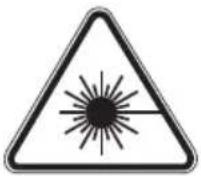
Laser device used in the power tool design is the class 2 with maximum power below 1mW and wavelength 650 nm. Such device is not dangerous to eyes, however do not look directly at the source of the light (temporary blindness hazard).
WARNING. Do not look directly at the source of the laser beam. It may cause hazards. Follow the below safety rules.
- Use the laser device in accordance with the manufacturer's instructions.
-
Do not, either intentionally or unintentionally, point the laser beam at people, animals or any object other than processed material.
-
Do not bring to accidental pointing the laser beam at bystanders' or animals' eyes for a period longer than 0.25 second, for instance by pointing the laser beam at mirrors.
- Always ensure the laser beam is directed at material which does not have any reflective surfaces. Reflective steel sheet does not allow for laser use, because it might cause hazardous light reflection directed at operator, bystanders or animals.
- Do not replace the laser unit with device of other type. All repairs must be carried out by the manufacturer or authorized person.
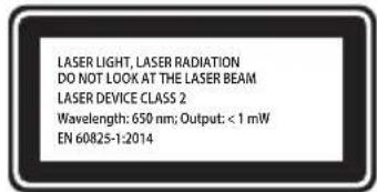
CAUTION: This device is designed to operate indoors.
The design is assumed to be safe, protection measures and additional safety systems are used, nevertheless there is always a small risk of injuries.
Explanation of used symbols

1

2
3

4

5

6
7
- Read instruction manual, observe warnings and safety conditions therein!
- Use personal protection measures (protective goggles, earmuff protectors)
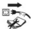
- Disconnect the power cord before starting maintenance or operation.
- Keep the tool away from children.
- Protect against rain.
- Protection class 2
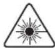
- Laser radiation. Do not look at laser beam
Adjustments other than described in this manual put in danger of exposition to laser radiation!
CONSTRUCTION AND USE
Mitre saw is the tool equipped with base, that allows to change angle of the cutting head attached to it. Additionally, the mitre saw cutting head can tilt at an angle and be extended for greater functionality and cutting length.
Mitre saw is designed for cutting wooden pieces that match with the tool size. Do not use the saw for cutting firewood. Use the saw accordingly to its purpose only. Attempts to use the saw for purposes other than specified will be considered an improper use. Use the saw only with appropriate cutting blades with teeth with sintered carbide inserts. The mitre saw is fit for use in workshop woodworking or for structural carpentry purposes.
Use the tool according to the manufacturer's instructions only!
DESCRIPTION OF DRAWING PAGES
Below enumeration refers to the device elements depicted on the drawing pages of this manual.
- Carrying handle
- Handle grip
- Switch
- Cutting blade guard lever
- Spindle lock button

-
Cutting blade shield
-
Carbon brush cover
-
Head locking pin
-
Cutting depth gauge
-
Cutting depth gauge adjustment screw
-
Guide locking knob
-
Guide
-
Head locking lever
-
Fence
-
Fixing hole
-
Angular scale of work table
-
Work table angle marker
-
Lever for automated position fixing
-
Work table locking knob
-
Table insert
-
Work table
-
Laser module cover
-
Laser unit
-
Fixed shield
-
Dust extraction outlet
-
Dust bag
-
Vertical clamp fixing knob
-
Vertical clamp arm
-
Vertical clamp arm locking knob
-
Work piece fixing knob
-
Angular scale of head tilt
-
Marker of head tilt position
-
Battery compartment
-
Laser switch button
-
Laser
-
Laser module fixing screws
-
Central plate fixing screw
-
Central plate
-
Adjustment knob for angle 0°
-
Adjustment knob for angle 45°
* Differences may appear between the product and drawing
MEANING OF SYMBOLS

CAUTION

WARNING

ASSEMBLY / SETTINGS

INFORMATION
EQUIPMENT AND ACCESSORIES
-
Dust bag - 1 pce
-
Special key - 1 pce
-
Vertical clamp - 1 pce
Ensure the mitre saw is disconnected from power supply before starting any installation or adjustment.
- Make sure the head is locked in the lowest position when carrying the mitre saw. - Make sure that work table locking knob, head locking lever, and other safety parts are tightened firmly.
INSTALLATION OF MITRE SAW ON A WORKBENCH

It is recommended to fix the mitre saw to a workbench or a stand with the use of fixing holes (15) designed for such purpose. They are located on the mitre saw base and guarantee safe operation and eliminate risk of unwanted machine shifts during operation. The holes allow to use coach bolts or bolts with hexagonal head and 8mm in diameter.

When fixing the mitre saw to a workbench ensure that:
• Workbench top surface is flat and clean.
- Bolts are tightened equally and with moderate force (fixing bolts must be tightened so the base is not under stress or deformed). In case of over-stress there is danger of cracking the base.
DUST EXTRACTION

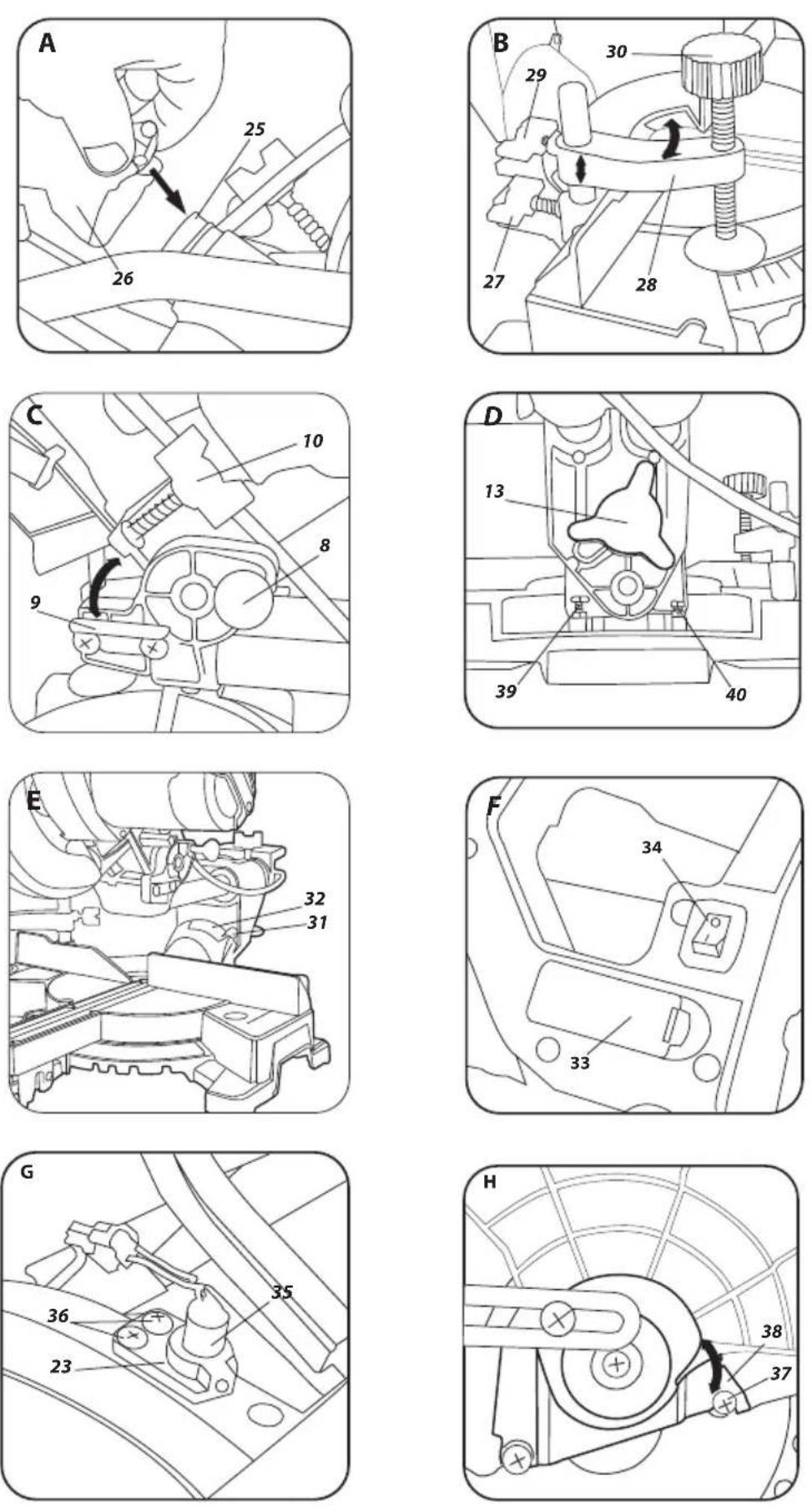
To prevent dust deposition and provide maximum working efficiency, you can connect the mitre saw and industrial vacuum cleaner using the dust extraction outlet (25). Alternatively, you can collect the dust in the dust-bag (included) after installing it onto dust extraction outlet. To install, press on the spring clamp and put the dust bag (26) onto the dust extraction outlet (25) (fig. A). To empty the dust bag, press on the spring clamp of the dust bag, remove it from the dust extraction outlet and open the zip-fastener that allows to access inside the bag.

To achieve optimal dust extraction empty the bag when it is 2/3 full.
USING THE SAW ARM (HEAD)

There are two positions of the saw arm, upper and lower. To release the saw arm from locked lower position, do as follows:
- Press and hold down the arm.
- Pull the head locking pin (8) out.
- Hold the saw arm as it lifts to its upper position.
To lock the saw arm in lower position, do as follows:
- Press and hold the cutting blade guard lever (4).
- Press down the saw arm until it reaches its lower position.
- Lock the extension arm in this position by pressing the head locking pin (8) in.
VERTICAL CLAMP

Vertical pressure clamp (fig. B) can be installed in the saw base at either side of the work table and is fully adjustable to size of the object to be cut. Do not use the saw without using vertical pressure clamp.
- Loosen the vertical clamp fixing knob (27) at the base, on the side where you plan to install the vertical clamp.
- To install the vertical clamp, slide it into the hole in the mitre saw base, next tighten the vertical clamp fixing knob (27) to the saw base.
- Once the vertical clamp arm (28) position is adjusted to work piece, tighten the vertical clamp arm locking knob (29).
- Tighten the work piece fixing knob (30) so the work piece is pressed against the work table (21).
- Make sure the work piece is secured.

Ensure the saw is disconnected from power supply network before starting any adjustment. To ensure safe, precise and efficient saw operation, proceed with all adjustment procedures as a whole.
After finishing all the setting and adjustment procedures ensure that all keys are collected. Check that all threaded joining elements are properly tightened.
When making adjustments ensure that all external parts work properly and are in good condition. Any worn out or damaged part must be replaced by qualified personnel before starting to use the saw.
SWITCHING ON / SWITCHING OFF

The mains voltage must match the voltage on the rating plate of the saw.
Switch on the saw only when cutting blade is away from the material that is to be cut.
Switching on
- Press and hold the switch button (3).
Switching off
- Release pressure on the switch button (3).
USING THE CUTTING DEPTH GAUGE


Cutting depth gauge is used for making key grooves in a work piece. To do so, partially cut the surface of the work piece, when the blade does not operate at its full travel range.
- Tighten the head locking lever (13).
- Loosen the guide locking knob (11) and move the head to the back.
- Tighten the guide locking knob (11).
- Turn the cutting depth gauge (9) to position for limited depth cutting (fig. C).
- Lower the saw arm and hold it in lower position, pressed against the cutting depth limiter.
- Turn the cutting depth gauge adjustment screw (10) clockwise or counter-clockwise (fig. C) until you obtain required sink of the cutting blade.
- Loosen the guide locking knob (11).
- Make a cut to defined depth.
- To return to cutting at full depth, turn the cutting depth gauge (9) to position, where the cutting depth adjustment screw (10) does not go into contact with the cutting depth gauge (9) when the extension arm is lowered.
SETTING THE WORK TABLE FOR MITRE CUTTING

Rotary extension arm allows for cutting material at any angle from the range of 45^ left or right from the perpendicular position.
- Pull away the head locking pin (8) and allow the arm to lift slowly to upper position.
- Loosen the work table locking knob (19).
- Press and hold the lever for automated position fixing (18) and turn the extension arm left or right, to obtain appropriate angle readout on the angular scale of work table (16).
- Lock by tightening the work table locking knob (19).

Angular scale of work table (16) features set of marked positions, where rotary extension arm fixes its position automatically. It is possible only when the lever for automated position fixing (18) is not pressed in during rotation of the extension arm, and can lock itself in factory predefined positions. Those are cutting angles that are used the most often (15^, 22,5^, 30^, 45^ , left or right). Any angle can be set precisely with the use of the angle scale of work table (16) scaled every degree. Even though the scale is accurate enough for most of performed tasks, it is recommended to double check the cutting angle with protractor or other device for angle measurements.
CHECKING AND ADJUSTMENT OF PERPENDICULAR POSITION OF CUTTING BLADE AND WORK TABLE

- Loosen the head locking lever (13).
- Set the head in the position 0^ (perpendicular to the work table) and tighten the head locking lever (13).
- Loosen the work table locking knob (19), press and hold the lever for automated position fixing (18).
- Set the work table in 0^1 position, release the lever for automated position fixing and tighten the work table locking knob (19).
- Press the cutting blade shield lever (4) and lower the saw head to the extreme down position.
- Use the tool to check perpendicularity of cutting blade and work table.

When making measurements make sure that measurement device does not touch any cutting blade tooth, otherwise the measurement may be inaccurate due to thickness of sintered carbide insert.

In case the measurement angle is different than 90^ , the following adjustment is necessary:
- Loosen securing nut and turn the adjustment knob for angle 0^ (39) (fig. D) clockwise or counter-clockwise, to increase or decrease cutting blade tilt angle.

- After perpendicular position of cutting blade and the work table has been set, allow the head to return to its upper position.
- Hold the adjustment knob for angle 0^ (39) and tighten the protection nut.
- Lower the head and check again that the angle previously set matches readings on the angular scale of the head tilt (31). Adjust position of the marker of head tilt position (32) when necessary (fig. E).
Carry out similar adjustment for bevel cutting at head angle 45^ , use the adjustment knob for angle 45^ (40) (fig. D).
CHECKING AND ADJUSTMENT OF PERPENDICULAR POSITION OF CUTTING BLADE AND FENCE

Carry out this procedure each time the fence was removed or replaced. Proceed with the adjustment only after setting cutting blade and work table perpendicular. Fence is used as a limiter for a work piece.
- Loosen the work table locking knob (19), press and hold the lever for automated position fixing (18) and set the work table in position 0^ .
- Lower the saw head to the extreme down position.
- Put a protractor or any other angle measurement device to cutting blade.
- Move the angle measurement device close to the fence (14).
• Measurement readout should be 90°.

In case adjustment is necessary:
- Loosen screws fixing the fence (14) to the base.
- Adjust fence (14) position, so it is perpendicular to the cutting blade.
- Tighten screws that fix the fence.
SETTING SAW ARM (HEAD) FOR BEVEL CUTTING
Saw extension arm can be tilted at any angle from the range of 0^ to 45^ for bevel cutting (fig. E).
- Pull the head locking pin (8) that releases saw arm and allow the saw arm to lift slowly to upper position.
- Loosen the head locking lever (13).
- Tilt the saw extension arm left to desired angle that you can read on the angular scale of head tilt (31), use the marker of head tilt position (32) (fig. E).
• Tighten the head locking lever (13).
If you need to set both angles (in both planes, horizontal and vertical) for compound cutting, always set the bevel angle first.
Laser device assembly generates laser beam that projects line on the material and shows how the material will be cut. Setting of laser line projection was adjusted during production process. Nevertheless check this setting before starting to cut for precise works.
- Place batteries in the battery compartment (33) (fig. F). Make sure to observe polarity.
- Set the work table in the position, where the work table angle marker (17) shows 0^ on the angular scale of work table (16), and the marker for head tilt position (32) (fig. E) shows 0^ on the angular scale of head tilt (31) (fig. E).
• Fix piece of waste material to the work table (21) and make a cut. - Release saw arm and leave waste material fixed to the work table of the saw.
- Set the laser switch button (34) to ON position 'I' (marked).
- Projected light beam should be parallel to the previously made kerf.

When setting laser guiding beam, do not look at the source of the laser beam or its reflection on a reflective surface. Always switch off the laser unit when the laser is not used.
Whenever projected light beam is not parallel to the previously made kerf, do as follows:

- Undo the fixing screws and remove the laser module cover (22). Beneath the laser module cover (22) you can find the laser module (23) (fig. G).
- Turn the laser (35) slightly clockwise or counter-clockwise (fig. G) in the laser module cover (23), until you obtain parallel position of the laser beam. Do not turn the laser module forcefully and by more than few degrees.
- When lateral adjustment is necessary, loosen the laser module fixing screws (36) and move the laser unit to the left or right, until the laser line is parallel to the kerf.

Dust arising from cutting may suppress laser light, therefore it is necessary to clean the generator lens occasionally.
SWITCHING ON THE MITRE SAW

Before pressing the switch button ensure that the mitre saw is assembled and adjusted properly and accordingly to instructions from this manual.

Described mitre saw is designed for right-handed persons.
- Press the switch button (3).
- Allow the saw motor to reach full rotational speed.
- Press the cutting blade guard lever (4).
- Lower saw arm towards processed material.
- Release pressure on the cutting blade guard lever (4).
- Make a cut.

STOPPING THE MITRE SAW
- Release pressure on the switch button (3) and wait until the cutting blade stops completely.
- Lift the saw extension arm to move it away from the processed material.

Temporary sparking of brushes inside the electric motor is normal when starting or stopping the mitre saw. Do not stop cutting blade by applying side pressure.
CUTTING WITH MITRE SAW

Fix a work piece so it does not impede using the mitre saw. Before switching the saw on, move its head to lower position to ensure that the saw head and cutting blade guard are free to move. Ensure the cutting blade guard can reach its extreme position.

Prior starting to cut ensure that work table locking knob (19) and head locking lever (13) are tightened firmly.
- Connect the saw to mains network.
- Ensure the power cord is away from cutting blade and the tool base.
- Place material on the work table and ensure it is securely fixed, so it cannot move during cutting.
- Move the saw head to the extreme back position and lock the guide (12) using the guide locking knob (11).
- Unlock head and cutting blade shield.
- Press the switch lock button and start the saw with the switch (wait until cutting blade reaches its top rotational speed).
- Lower the saw head slowly.
- Start cutting by moderately pressing the head down.

Insufficient tightening of the locking knobs may cause unexpected move of cutting blade towards upper surface of the material. It puts operator in danger of being hit with piece of material.
CUTTING WITH MOVING THE SAW EXTENSION ARM (HEAD) OF THE MITRE SAW

Saw extension arm shift allows to move cutting blade to the back and front, and to cut wider pieces of material.
- Lift the saw arm to the upper position.
- Loosen the guide locking knob (11).
- Before switching on the saw pull the saw extension arm to yourself while holding it in the upper position.
- Press the switch button (3) to start the saw.
- Wait until the cutting blade rotates at its maximum speed.

- Unlock the cutting blade guard by pressing the cutting blade guard lever (4).
- Lower saw extension arm and start cutting.
- When cutting, move the saw extension arm to the back (away from yourself).
- After the piece has been cut, release pressure on the switch button, and before you lift the saw arm to the upper position wait until cutting blade stops rotating.
Never cut by moving the saw head towards yourself. Otherwise cutting blade might catch the work piece, it puts the operator in danger of a kick-back.
Unplug the power cord from mains socket before commencing any activities related to installation, adjustment, repair or maintenance.
CLEANING
- When the work is finished, remove thoroughly all pieces of material, scobs and dust from the work table insert, area around cutting blade and its shield.
- Ensure the ventilation holes of the motor cover are unobstructed, with no scobs or dust.
- Clean guides and apply thin layer of solid grease.
- Keep all handles and knobs clean.
- Clean laser projector lens with a brush.
CUTTING BLADE REPLACEMENT
- Press the cutting blade guard lever (4).
- Lift the cutting blade shield (6) and undo the central plate fixing screw (37) (fig. H).
- Move the central plate (38) left, so to gain access to the cutting blade fixing bolt.
- Press the spindle lock button (5) and rotate cutting blade until it locks.
- Use the special wrench (included) to loosen and unscrew the cutting blade fixing bolt.
- Remove the outer washer, remove the cutting blade (pay attention to adapter ring, if present).
- Remove all dirt from the spindle and washers that fix cutting blade.
- Follow described procedure in reverse order to install new cutting blade.
- After finishing the procedure ensure all keys and adjustment tools were removed and all screws, wheels and bolts are tightened firmly.

Screw that secures cutting blade is left-hand threaded. Be very careful when gripping the cutting blade. Use protective gloves to provide protection for your hands against sharp teeth of cutting blade.
BATTERY REPLACEMENT IN LASER UNIT

Laser unit is powered with two AAA batteries, 1.5 V.
- Remove battery compartment (33) lid (fig. F).
- Remove empty batteries.
- Insert new batteries. Observe polarity.
• Install battery compartment lid.
REPLACEMENT OF CARBON BRUSHES

Immediately replace worn out (shorter than 5 mm), burnt or cracked motor carbon brushes. Always replace both brushes at a time.
- Unscrew and remove carbon brush covers (7).
- Remove used brushes.
- Remove any carbon dust with compressed air.
- Insert new carbon brushes (brushes should easily move into brush holders).
• Fix carbon brush covers (7).


After replacement of carbon brushes, start the power tool with no load and wait 1–2 minutes until the carbon brushes fit to the motor commutator. Entrust replacement of carbon brushes only to a qualified person. Only original parts should be used.
All defects should be repaired by service workshop authorized by the manufacturer.
TECHNICAL PARAMETERS
RATED PARAMETERS
| Mitre Saw | |
| Parameter Value | |
| Supply voltage 230V AC | |
| Power supply frequency 50Hz | |
| Rated power 1400W | |
| Spindle rotational speed with no load | 5000 min^-1 |
| Mitre cutting range ± 45^ | |
| Bevel cutting range 0^ - 45^ | |
| Outer diameter of cutting blade 185 mm | |
| Hole diameter of cutting blade 16 mm | |
| Cutting capacity (material size)mitre / bevel | 0^ × 0^ 50 × 210 mm |
| 45^ × 0^ 50 × 150 mm | |
| 45^ × 45^ 35 × 150 mm | |
| 0^ × 45^ 35 × 210 mm | |
| Guide length | 135 mm |
| Laser class | 2 |
| Laser power | < 1mW |
| Laser wavelength | = 650 nm |
| Protection class II | |
| Weight | 11 kg |
| Year of production | 2020 |

NOISE LEVEL AND VIBRATION PARAMETERS
Information on noise and vibrations
The emitted noise levels, such as the level of emitted acoustic pressure Lp_A and the level of acoustic power Lw_A' and the measurement uncertainty K are given below in the instruction in accordance with the EN 61029-2-9 standard.
The vibration values a_h and the measurement uncertainty K, determined in accordance with the EN 61029 standard, are given below.
The vibration level given below in this instruction was measured in accordance with a measurement procedure set forth in the EN 61029 standard and can be used for comparing power tools. It can also be used for preliminary evaluation of exposure to vibrations.
The vibration level given here is representative for the basic uses of the power tool. If the power tool is used for other purposes or with other bits, or if the power tool is not maintained properly, the vibration level may change. Also, these conditions may also result in an increased exposure to vibrations during the entire work period. In order to accurately estimate exposure to vibrations, one must consider periods when the power tool is switched off or when it is switched on and not used for work. This way, the total exposure to vibrations may turn out to be much lower. One must implement additional safety measures in order to protect the user from the consequences of vibrations, such as maintenance of the power tool and of the working tools, ensuring proper temperature of the hands, and proper organization of work.
Sound pressure level: Lp_A=91,9 dB(A) K=3 dB(A)
Sound power level: Lw_A=104,9 dB(A) K=3 dB(A)
Vibration acceleration: a_h<2,5 m/s^2 K=1,5 m/s^2
ENVIRONMENT PROTECTION
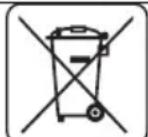
Electrical equipment must not be disposed off with household waste and, instead, should be utilized at appropriate facilities. Information on utilization can be provided by the product vendor or the local authorities. Waste electrical and electronic equipment contains substances that are not neutral to the natural environment. Equipment that is not recycled constitutes a potential hazard to the environment and to human health.
* Right to introduce changes is reserved.
"Grupa Topex Spółka z ograniczoną odpowiedzialnością" Spółka komandytowa with seat in Warsaw at ul. Pograniczna 2/4 (hereinafter Grupa Topex) informs, that all copyrights to this instruction (hereinafter Instruction), including, but not limited to, text, photographs, schemes, drawings and layout of the instruction, belong to Grupa Topex exclusively and are protected by laws accordingly to Copyright and Related Rights Act of 4 February 2004 (justawa o prawie autorskim i prawach pokrewnych, Dz. U. 2006 No 90 item 631 with later amendments). Copying, processing, publishing, modifications for commercial purposes of the entire Instruction or its parts without written permission of Grupa Topex are strictly forbidden and may cause civil and legal liability.

ÜBERSETZUNG DER
MANIPULACE S VÝSUVNÝM RAMENEM (HLAVOU)

GRAFISKÄS DALAS APRAKSTS
POSEBNI PROPISI O SIGURNOSTI
MJERE OPREZA:
AFVOEREN VAN HET STOF

- INSTRUKCJA ORYGINALNA (OBSŁUGI)
- PILARKA UKOSOWA 59G800
- SZCZEGÓŁOWE PRZEPISY BEZPIECZEŃSTWA
- ŚRODKI OSTROŻNOŚCI:
- DETAILED SAFETY REGULATIONS
- PRECAUTIONS:
- SAFE OPERATION:
- SAFETY RULES FOR LASER DEVICE
- CAUTION: This device is designed to operate indoors.
- Explanation of used symbols
- CONSTRUCTION AND USE
- Use the tool according to the manufacturer's instructions only!
- DESCRIPTION OF DRAWING PAGES
- MEANING OF SYMBOLS
- EQUIPMENT AND ACCESSORIES
- INSTALLATION OF MITRE SAW ON A WORKBENCH
- DUST EXTRACTION
- USING THE SAW ARM (HEAD)
- VERTICAL CLAMP
- SWITCHING ON / SWITCHING OFF
- Switching off
- USING THE CUTTING DEPTH GAUGE
- SETTING THE WORK TABLE FOR MITRE CUTTING
- CHECKING AND ADJUSTMENT OF PERPENDICULAR POSITION OF CUTTING BLADE AND WORK TABLE
- CHECKING AND ADJUSTMENT OF PERPENDICULAR POSITION OF CUTTING BLADE AND FENCE
- SETTING SAW ARM (HEAD) FOR BEVEL CUTTING
- SWITCHING ON THE MITRE SAW
- STOPPING THE MITRE SAW
- CUTTING WITH MITRE SAW
- CUTTING WITH MOVING THE SAW EXTENSION ARM (HEAD) OF THE MITRE SAW
- CLEANING
- CUTTING BLADE REPLACEMENT
- BATTERY REPLACEMENT IN LASER UNIT
- REPLACEMENT OF CARBON BRUSHES
- TECHNICAL PARAMETERS
- NOISE LEVEL AND VIBRATION PARAMETERS
- Information on noise and vibrations
- ENVIRONMENT PROTECTION
- ÜBERSETZUNG DER
- MANIPULACE S VÝSUVNÝM RAMENEM (HLAVOU)
- GRAFISKÄS DALAS APRAKSTS
- POSEBNI PROPISI O SIGURNOSTI
- MJERE OPREZA:
- AFVOEREN VAN HET STOF
Brand : Graphite
Model : 59G800
Category : Saw