
59G019 - Uncategorized Graphite - Free user manual and instructions
Find the device manual for free 59G019 Graphite in PDF.


| Product Type | Label Printer |
| Model | 59G019 |
| Brand | Graphite |
| Dimensions (HxWxD) | 150 x 200 x 120 mm |
| Weight | 1.2 kg |
| Power Supply | AC 100-240V, 50/60 Hz or 6 x AA batteries |
| Print Technology | Thermal transfer |
| Max Print Resolution | 203 dpi |
| Max Label Width | 24 mm |
| Print Speed | Up to 10 mm/s |
| Display | LCD with backlight, 2 lines x 16 characters |
| Keyboard | QWERTY, 45 keys |
| Memory | Up to 99 stored labels |
| Supported Languages | English, French, German, Spanish, Italian |
| Barcode Support | EAN-13, Code 128, Code 39, etc. |
| Connections | USB 2.0 (for PC connection) |
| Included Accessories | 1 starter tape cartridge, USB cable, user manual |
| Maintenance | Clean print head with alcohol swab after every 5 tape changes |
| Safety | Do not expose to moisture; use only recommended AC adapter |
| Spare Parts / Repairability | Replacement print head and cutter available; self-service repair |
Frequently Asked Questions - 59G019 Graphite
User questions about 59G019 Graphite
0 question about this device. Answer the ones you know or ask your own.
Ask a new question about this device
Download the instructions for your Uncategorized in PDF format for free! Find your manual 59G019 - Graphite and take your electronic device back in hand. On this page are published all the documents necessary for the use of your device. 59G019 by Graphite.
USER MANUAL 59G019 Graphite
natural_image
Line drawing of a GRAPHITE electric drill with attached screwdriver (no text or symbols on device)PL MINISZLIFIERKA
GB MINIGRINDER
DE MINISCHLEIFMASCHINE
RU МИНИ-ШЛИФОВАЛЬНАЯ МАШИНА
UA МІНІШЛІФМАШИНКА
HU MULTIFUNKCIÓS FÚRÓGÉP
RO MINIPOLIZOR
© MINIBRUSKA
SK BRÚSKA MINI + PRÍSLUŠENSTVO
SL MINI BRUSILNIK
10* LAT DOSTĘPNOŚCI CZĘŚCI ZAMIENNYCH
LT MINI ŠLIFUOKLIS
LV SLIPMAŠINA MINI
MINIJAHVATI TELESKOOPALUS
BG ШЛАЙФ МИНИ
HR BRUSILICA MINI
SR BRUSILICA MINI
GR TPIBEIO APLO
ES MINI AMOLADORA RECTA
IT MINI RETTIFICATRICE
NL MINI SLIJPMACHINE
natural_image
Completely dark image with no visible content, text, or symbols.PL INSTRUKCJA OBSŁUGI 6
GB INSTRUCTION MANUAL ....17
DE BETRIEBSANLEITUNG....25
RU РУКОВОДСТВО ПО ЭКСПЛУАТАЦИИ .....34
UA ІНСТРУКЦІЯ З ЕКСПЛУАТАЦІЇ .....44
HU HASZNÁLATI UTASÍTÁS....54
RO INSTRUCTIUNI DE DESERVIRE .....63
© INSTRUKCE K OBSLUZE....72
SK NÁVOD NA OBSLUHU....81
SL NAVODILA ZA UPORABO .....90
LT APTARNAVIMO INSTRUKCIJA. . . . . . . . . . . . . . . . . . . . . . . . . . . . . . . . . . . . . . . . . . . . . . . . . . . . . . . . 99
LV LIETOŠANAS INSTRUKCIJA 108
EE KASUTUSJUHEND ....116
BG ИНСТРУКЦИЯ ЗА ОБСЛУЖВАНЕ ..... 125
HR UPUTE ZA UPOTREBU....135
SR UPUTSTVO ZA UPOTREBU 144
GR OΔΗΓΙΕΣ ΧΡΗΣΗΣ 153
ES INSTRUCCIONES DE USO....164
IT MANUALE PER L'USO 173
NL GEBRUIKSAANWIJZING 183
MINISZLIFIERKA
59G019
1

natural_image
Icon of a person using a laptop inside a circle (no text or symbols)2

natural_image
Simple icon of a person wearing headphones and sunglasses (no text or symbols)3

natural_image
Weather symbol with cloud and raindrops (no text)4

natural_image
Simple geometric diagram with two concentric squares (no text or symbols)5


DETAILED SAFETY REGULATIONS

MINIGRINDER. SAFETY WARNINGS
Safety guidelines for grinding, polishing, milling, paper sanding, use of wire brushes and cutting with grinding wheels.
- This power tool can be used as a grinder, polisher, milling machine, cutter, sander and with wire brushes. Follow all safety guidelines, instructions, descriptions and information supplied with the power tool. Failure to observe below guidelines may create risk of electric shock, fire and/or serious body injury.
- Do not use equipment not designed and not recommended by the manufacturer for use with this power tool. Possibility of equipment installation in the power tool alone does not guarantee safe use.
- Rated speed of grinder accessories must be at least maximum power tool speed. Grinder accessories that operate at speed greater than rated may crack and break into pieces.
- Outer diameter and thickness of work tool must match with power tool dimensions. Work tools with incorrect dimensions may be insufficiently guarded or controlled.
- Grinding wheels, stones and other equipment must be exact match to spindle or holder of used power tool. Accessories that do not match to attachment part of the power tool result in uneven rotation, hard vibrations and may cause loss of control over the power tool.
- Grinding wheels, abrasive rollers, cutting discs and any other working tool installed on a shaft must be completely slid into holder or drill chuck. Make sure to reduce protruding part of shank or part of shank between grinding wheel and tool holder. If shank is incorrectly tightened or grinding wheel is too far from holder, working tool may get loosened and projected with high speed.
- Do not use damaged working tools under any circumstances. Check equipment before each use, e.g. grinding wheels for dents and cracks, abrasive rollers for cracks, abrasion or heavy wear, wire brushes for loose or broken wires. In case of dropping power tool or work tool, make sure it is not damaged or use other, undamaged tool. After work tool has been checked and installed, start the power tool and leave it operating at maximum speed for one minute. Be careful to stay outside of rotating work tool range and that no bystander is in that range. Damaged tools mostly break within such test time.
- Wear personal protection equipment. Depending on the task, use protective mask that shields whole face, eye protection or safety glasses. When necessary use anti-dust mask, hearing protectors, work gloves or special apron that protects against small particles of grinding and grinded material. Protect eyes against floating particles produced at work. Anti-dust mask and respiratory protection must filter dust produced at work. Prolonged exposure to noise may lead to hearing loss.
- Make sure to keep bystanders at safe distance from power tool range. Each person close to operating power tool must use personal protection equipment. Splinters of processed piece or cracked working tool can chip off and cause damage also beyond direct range.
- Whenever tool can hit hidden electric wires or its own power cord during operation, hold it only by insulated surfaces of the handle. Contact with power supply line may transfer voltage to metal parts of the power tool and cause electric shock.
- Always hold power firmly tool during start up. In acceleration phase to full speed motor creates reaction torque that tries to rotate the power tool in hand.
- If possible, use clamps or vice to fix work piece. Never hold small work pieces in one hand and power tool in the other. Fixing small pieces in vice allows to guide the power tool with both hands and achieve greater control. Cutting round pieces, e.g. pins of wood, rods or pipes may cause unpredictable rotation of work piece, cause locking of work tool which in consequence can kick back towards operator.
GRAPHITE
- Keep power cord away from rotating work tools. Loss of control over the power tool can lead to cutting or catching the power cord, also hand or whole arm can get into rotating work tool.
- Never put away the power tool before work tool comes to complete stop. Rotating tool can contact the surface it is put on, which can cause loss of control over the power tool.
- Firmly tighten holder nut and other fixing pieces after replacement of work tools or readjusting the tool. Loose fixing parts can move unexpectedly and cause loss of control over the power tool. Loose rotating pieces can be projected with high energy.
- Do not carry around the power tool when it is rotating. Accidental contact of rotating work tool with clothes may cause its catching and drilling of work tool into operator's body.
- Clean ventilation holes of power tool on regular basis. Motor blower sucks dust into casing and large depositions of metal dust may cause electric risk. Do not use power tool in proximity of flammable materials. Sparks can cause ignition.
- Do not use tools that require liquid coolant. Use of water or other liquid coolants may cause electric shock.
KICK BACK AND RELEVANT SAFETY TIPS
- Kick back is a sudden power tool reaction to locking or catching of rotating work tool, such as grinding wheel, disc, wire brush etc. Catching or locking causes sudden stopping of rotating work tool. Uncontrolled power tool is then pulled in direction opposite to work tool rotations. E.g. when grinding wheel jams itself in processed piece, wheel edge plunged in material may lock and cause breaking off or kick back. Grinding wheel movement (towards or away from operator) then depends on grinding wheel rotation in the place it locked. Grinding wheel may also break. Kick back is a result of inappropriate use of power tool. It can be avoided by observing below mentioned safety precautions.
- Hold the power tool firmly, position your hands and body to limit kick back effect. Always use additional handle when it is included in standard equipment, to have the greatest possible control of kick back forces and counter torque during start up. Tool operator can control sudden pulling and kick back effect by observing appropriate safety precautions.
- Be very careful when processing corners, sharp edges etc. Prevent rebound or locking of work tools. Rotating work tool is more susceptible to jamming when processing corners, sharp edges or after rebound. It can cause loss of control or kick back.
- Do not use toothed blades. Work tools of this type often cause kick back or loss of control over power tool.
- Always engage work tool with material in accordance with direction of rotation as marked on the tool. Guiding power tool in wrong direction will eject work tool cutting edge from work piece which will cause power tool pulling in advance direction.
- Always firmly fix work piece before processing with rotary files, high speed milling tools or solid carbide mills. Even slight tilt of work tool in groove may cause its jamming and kick back. Jamming of file, high speed mill or solid carbide mill may eject work tool from groove and cause loss of control over the power tool.
SPECIAL SAFETY DIRECTIONS FOR GRINDING AND CUTTING WITH GRINDING WHEEL
- Only use grinding wheels designed for the power tool and shield designed for the wheel. Grinding wheels that are not proper accessories for given power tool may not be sufficiently shielded and safe.
- For conical and cylindrical rotary shafts use only grinders of proper size and length, with no undercut on their seating. Such grinding tools reduce possibility of breaking.
- Avoid jamming of cutting wheel and excessive pressure. Do not make too deep cuts. Overloading a cutting wheel increases its load and risk of jamming or locking, and in consequence kick back or wheel breaking.
- Do not put your hands in front of and behind rotating cutting wheel. In the event of kick back, cutting wheel advance in work piece away from you may cause bouncing of the power tool with rotating wheel towards your hand.
-
In the event of jamming or locking of cutting wheel or having a break in work, switch off the power tool and wait until wheel comes to complete stop. Never attempt to remove rotating wheel from cut material, as this may cause kick back. Try to eliminate cause of jamming or locking of wheel.
-
Do not switch on the power tool back, when it is still in processed material. Before cutting again, cutting wheel should reach its full rotational speed. Otherwise the grinding wheel may catch material, bounce out of work piece or cause kick back.
- Support sheets and large objects before processing to minimise risk of kick back caused by jammed wheel. Large objects can bend under own weight. Support work piece on both sides, at cutting line and near edge.
- Be careful when cutting holes in walls and operating in other areas with reduced visibility. Wheel plunging into material may cause kick back after hitting gas lines, water pipes, electric wires and other objects.
SPECIAL SAFETY DIRECTIONS FOR WORKING WITH WIRE BRUSHES
- Remember that even during normal use brush loses pieces of wire. Do not overload wires by excessive pressure. Flying pieces of wire can easily penetrate through thin clothes and/or skin.
- Start the power tool before work so the brush can rotate at normal working speed for at least one minute. Make sure that no one stands in front of the brush or in its plane of rotation. Pieces of wire may get loose and project in phase of power tool acceleration.
- Do not point rotating wire brush at yourself. When working with wire brushes small pieces of wire may be projected with high energy and puncture skin.
ADDITIONAL SAFETY PRECAUTIONS
- Do not use flexible drive shaft when it is bended too much. Too tight bend may cause overheating of flexible casing.
- Disconnect the minigrinder from power supply network before starting any adjustments or replacement of accessories. Doing otherwise may lead to unexpected body injury.
- Never leave the minigrinder switched on without any supervision. Disconnect the power supply first. You can put the minigrinder away only after the spindle stops rotating.
- Do not touch the work tool (stone or tip) just after finishing operation. Those elements heat up very much during operation.

CAUTION: This device is designed to operate indoors.
The design is assumed to be safe, protection measures and additional safety systems are used, nevertheless there is always a small risk of injuries.
EXPLANATION OF USED SYMBOLS

1

natural_image
Icon of a person using a laptop inside a circle (no text or symbols)2

natural_image
Simple icon of a person wearing headphones and sunglasses (no text or symbols)3

natural_image
Weather symbol with cloud and raindrops inside a prohibition sign (no text)4

natural_image
Simple geometric diagram with two concentric squares (no text or symbols)5
- Warning, use precaution measures
- Read instruction manual, observe warnings and safety conditions therein!
- Use personal protection measures (protective goggles, earmuff protectors)
- Protect against rain.
- Protection class 2
CONSTRUCTION AND USE
Minigrinder is a hand-operated power tool with insulation class II. The tool is driven by single-phase commutator motor. Minigrinder is designed for precise mechanical working of metal, wood, glass and plastic objects. All accessories (working tools) supplied with the minigrinder should be used according to their purpose, bearing in mind type and conditions of the task ahead. Range of use covers model-making, precise working on above mentioned materials, and any work from the range of individual, amateur DIY activities.


The tool is designed for dry operation only. Use the power tool according to its purpose only.
Inappropriate use.
- Do not process materials that contain asbestos. Asbestos is a carcinogen.
- Do not process materials that produce flammable or explosive dust. During operation power tool produces sparks that can ignite produced fumes.
- Do not grind with wheels designed for cutting. Cutting wheels work with front edge surface and grinding with side surface of the wheel can cause damage, and in consequence personal injuries of the operator.
DESCRIPTION OF DRAWING PAGES
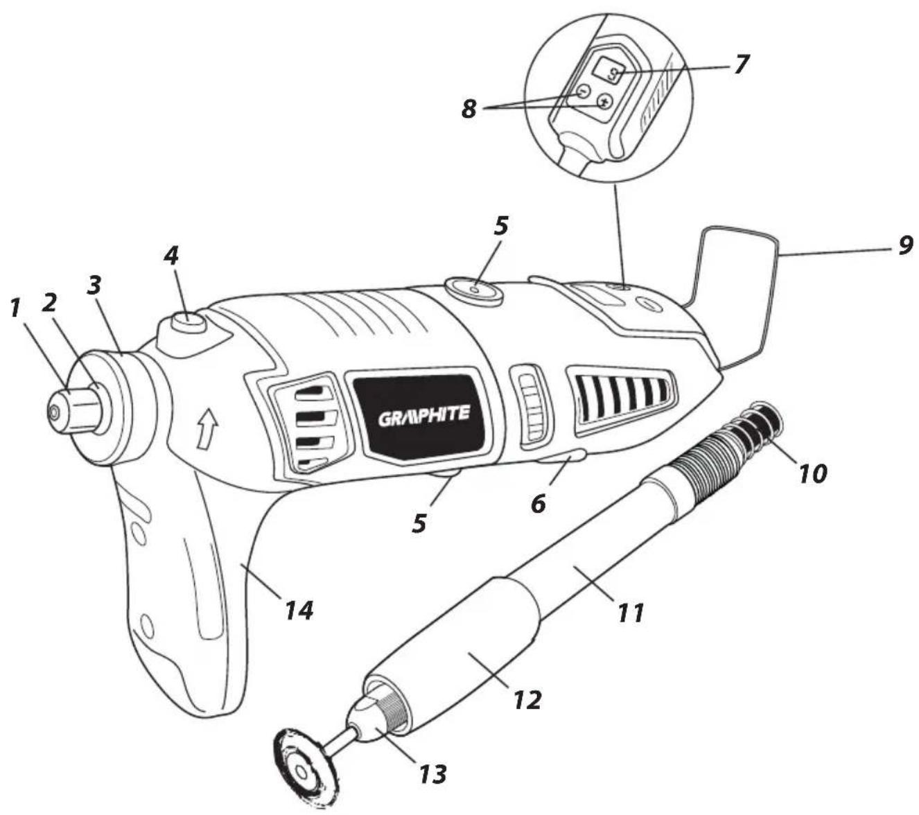
Below enumeration refers to the device elements depicted on the drawing pages of this manual.
- Cap of the spindle collet sleeve
- Spindle
- Guard
- Spindle lock button
- Carbon brush cover
- Switch
- Display
- Buttons for control of rotation speed
- Hanger
- Flexible casing
- Flexible shaft handle
- Sleeve for flexible shaft cord locking
- Cap of the collet sleeve of the flexible shaft
- Auxiliary handle
* Differences may appear between the product and drawing.
MEANING OF SYMBOLS

CAUTION

WARNING

ASSEMBLY/SETTINGS

INFORMATION
EQUIPMENT AND ACCESSORIES
- Flexible shaft - 1 pce
- Special flat spanner - 1 pce
- Additional guard - 1 pce
- Auxiliary handle (attached to the tool) - 1 pce
- Various accessories - 190 pcs
- Plastic case - 1 pce
You can use minigrinder with or without auxiliary handle (14), according to your needs. Therefore, use proper guard (3) with high or low flange.

Depending on the work ahead it is recommended to use auxiliary handle and hold the minigrinder with both hands.

Disconnect the power tool from power supply.

• Unscrew and remove the guard (3).
Put auxiliary handle (14) on the tool body.
• Install and tighten appropriate guard (3).

INSTALLATION AND REMOVAL OF COLLET SLEEVE CAP
Disconnect the minigrinder from power supply.

- Press and hold the spindle lock button (4) to prevent spindle rotation.
- Turn the collet sleeve cap (1), so the spindle lock pin gets into groove in the drive shaft.
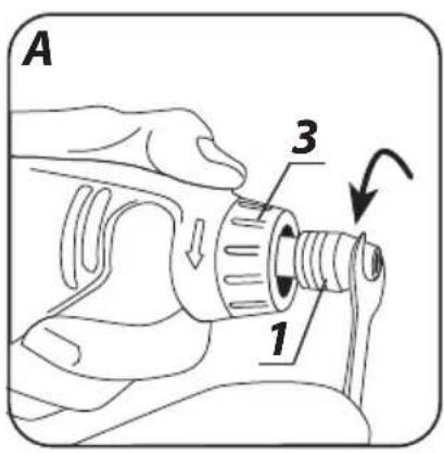
- Unscrew the collet sleeve cap (1) (if needed, use special spanner) (fig. A).

Installation of the collet sleeve cap is similar to removal, only the sequence of actions is reversed.
REPLACEMENT OF COLLET SLEEVE

Always use appropriate collet sleeve that matches working tool shaft that you plan to use. Do not try to force work tool shaft of a given diameter into a smaller collet sleeve.

Disconnect the power tool from power supply.

- Press and hold the spindle lock button (4).
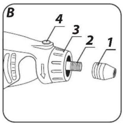
- Undo and remove collet sleeve cap (1) (fig. B).
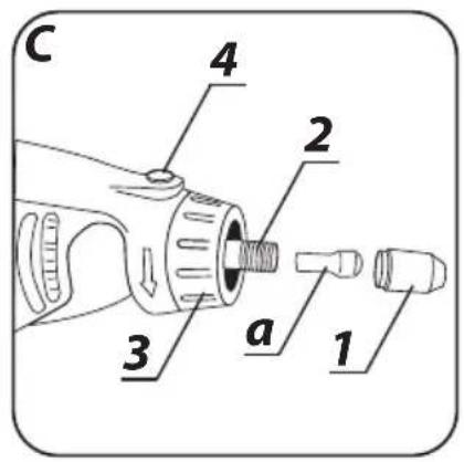
- Remove the collet sleeve 'a' by pulling it from the spindle (2) (fig. C).
• Install collet sleeve of appropriate size. - Tighten the collet sleeve cap (1).

Do not screw the collet sleeve cap tight without work tool inserted.

Use the same method to replace collet sleeve.
INSTALLATION AND REPLACEMENT OF ACCESORIES

Unplug the power cord from mains socket before commencing any maintenance activities, installation or replacement of work tools or collet sleeve.

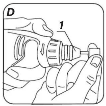
- Press and hold the spindle lock button (4).
- Loosen the collet sleeve cap (1).
- Insert work tool shaft into the collet sleeve so it cannot slip off during operation (fig. D).
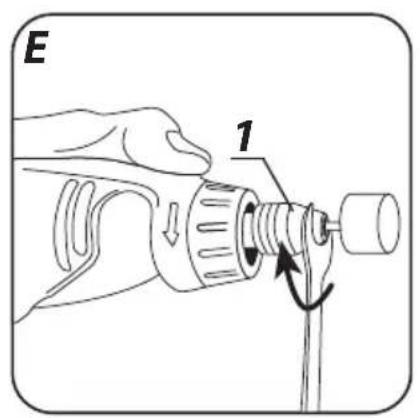
- With spindle lock button (4) pressed, tighten the collet sleeve cap (1) so the collet sleeve tightens firmly on the work tool shaft (use special spanner if necessary) (fig. E).

Spindle lock button can be used only for working tool installation or removal. It cannot be used as a brake-button when the spindle of the tool is rotating.

Grinding wheels, grinding stones and other equipment must be exact match to collet sleeve of spindle or drive shaft.
Work tool must be inserted to depth of at least 10 mm.

INSTALLATION OF FLEXIBLE DRIVE SHAFT
Remove power cord plug from mains socket.

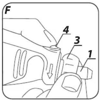
- Loosen and remove front plastic guard (3) (fig. F).
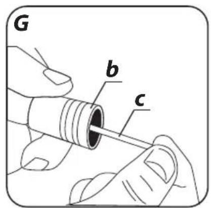
- Pull some of the cord 'c' from flexible shaft casing (10) so its end can be installed in the collet sleeve (fig. G).
- Press and hold spindle lock button (4).
- If necessary, turn the spindle slightly so it locks.
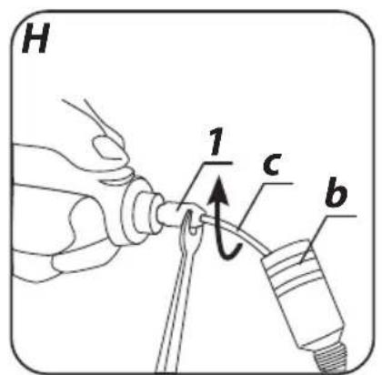
- Tighten the collet sleeve cap (1) with supplied special flat spanner (fig. H).
- Allow the cord to move back into the flexible shaft casing (10).
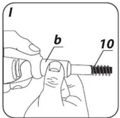
- Secure the flexible shaft by tightening the positioning nut 'b' (fig. I).

INSTALLATION AND REPLACEMENT OF ACCESSORIES IN FLEXIBLE SHAFT HOLDER
Remove power cord plug from mains socket.

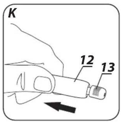
- Lock flexible shaft cord 'c' by pulling back and holding sleeve for flexible shaft cord locking (12) (fig. K).
- Loosen the flexible shaft collet sleeve cap (13).
- Insert work tool shank into collet sleeve.
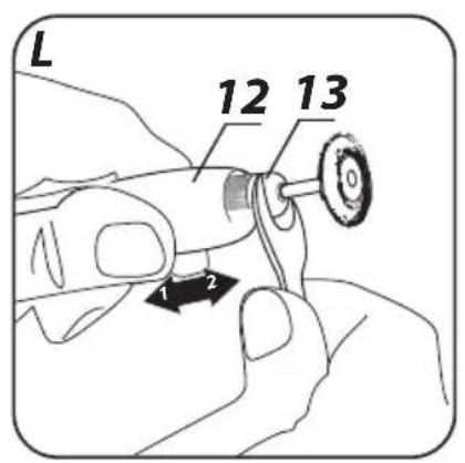
- Tighten firmly the collet sleeve cap (13) with special spanner (fig. L).
- Release the sleeve for flexible shaft cord locking (12).

Convenient hanger (9) allows to hang the minigrinder on a stand during breaks at work.
Check the grinding wheel before using the minigrinder. Do not use wheels with dents, cracks or other damages. Replace worn out wheel or brush with a new one before operation. After work is finished always turn the tool off and wait until the work tool comes to complete stop. Only then you can put the minigrinder away. Do not brake rotating grinding wheel by pushing it against processed material.

SWITCHING ON / SWITCHING OFF
Mains voltage must match the voltage on the rating plate of the minigrinder.

Switching on - set the switch button (6) to position I.
Switching off - set the switch button (6) to position 0.
ADJUSTMENT OF SPINDLE ROTATIONAL SPEED

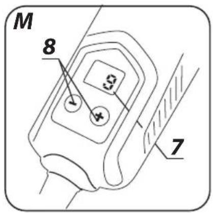
- After setting the switch (6) position to 'I' you can change spindle rotational speed by choosing appropriate number shown on the display (7) (range from 8 to 35) (fig. M).
- You can change rotational speed by pressing buttons '+' and '-' (8).
- Press the button '+' (many times if needed) to increase speed.
- Press the button '-' (many times if needed) to decrease speed.

To achieve the best results when working on different materials, set the rotational speed of the minigrinder spindle accordingly to the task at hand. To choose correct rotational speed it is recommended to make few tests using waste pieces of material.
RECOMMENDED ROTATIONAL SPEEDS FOR MINIGRINDER OPERATION

Rotational speed depends on voltage changes. When the power supply voltage is lowered, the rotational speed of the spindle will drop as well, especially when it is set to low value. The minigrinder might not start on the lowest speed setting, when the supply voltage is lower than 230 V. To start the operation, set higher rotational speed.
Operation with low rotational speed (15,000 rpm or lower) is best for polishing with polishing accessories made of felt, for delicate processing of wood and fragile model parts. All brushing works require lower rotational speeds to avoid pulling wires off from brushes. Apply the rule to proceed with the work at the lowest speed that is reasonable for working tool and processed material.
Higher rotational speeds are better for drilling, shaping, cutting, profiling, making grooves for keys, shape machining in wood.
Hard wood, metals and glass also require higher settings of the spindle rotational speed.

Respective settings on the display provide following spindle rotational speeds:
| Set value Spindle speed (min ^-1 ) | |
| 8 8000 | |
| 9 9000 | |
| 10 10000 | |
| 11 11000 | |
| . | . |
| . | . |
| . | . |
| 34 34000 | |
| 35 35000 | |

Some materials, such as certain plastics and metals may be damaged due to heat produced during high speed processing. They have to be processed with appropriately lower speeds. Always use goggles or impact glasses when operating the minigrinder. Failure to follow this recommendation may cause serious body injuries (especially eyes), when small particles of a workpiece or working tool elements, such as pieces of wire brushes, are projected by the working power tool.
CUTTING

Fix small pieces, e.g. in a vice. Fix material so the cutting place is located near fixing tool. This will ensure greater precision when cutting.

Cutting wheels heat up to high temperatures during operation – do not touch them with unprotected parts of your body before they cool down.
GRINDING

When grinding do not use wheels designed for cutting.

Grinding wheels are designed to remove material with wheel edge.

Do not use side surface for grinding. Optimum work angle for such wheels is 30^ .

When using flap wheels, abrasive cloth wheels and elastic discs with abrasive paper make sure to keep the right work angle.
- Do not use whole wheel surface for grinding or sanding.
• Such wheels are used for processing of flat surfaces.

Wire brushes are mainly used for cleaning sections and hard to reach areas. They can remove rust, paint coatings, etc.
Disconnect the tool from power supply network before starting any adjustment, maintenance or repair.
MAINTENANCE AND STORAGE

- Cleaning the device after each use is recommended.
- Do not use water or any other liquid for cleaning.
- Clean the tool with a dry cloth or blow with compressed air at low pressure.
- Do not use any cleaning agents or solvents, they may damage plastic parts.
- Clean ventilation holes in the motor casing regularly to prevent device overheating.
- In case of power cord damage replace it with a cord with the same specification. Entrust the repair to qualified specialist or return the tool to a service point.
- In case of excessive commutator sparking, have the technical condition of carbon brushes of the motor checked by qualified person.
• Always store the tool in a dry place, beyond reach of children.
REPLACEMENT OF CARBON BRUSHES

Immediately replace worn out (shorter than 5 mm), burnt or cracked motor carbon brushes. Always replace both carbon brushes at a time.

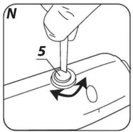
• Unscrew carbon brush covers (5) (fig. N).
- Remove worn out carbon brushes.
- Remove any carbon dust with low pressure compressed air.
- Insert new carbon brushes (brushes should easily move into brush holders).
• Fix carbon brush covers (5).

After replacement of carbon brushes, start the tool with no load and wait 2–3 minutes until the carbon brushes fit to the motor commutator. Entrust replacement of carbon brushes only to qualified person. Only original parts should be used.

All defects should be repaired by service workshop authorized by the manufacturer.
SPECIFICATIONS
RATED DATA
| Minigrinder | |
| Parameter Value | |
| Power supply voltage 230 V AC | |
| Power supply frequency 50 Hz | |
| Rated power 170W | |
| Idle speed range: 8000 ÷ 35000 min | -1 |
| Max. grinding wheel diameter 35 mm | |
| Collet 1.6; 2.4; 3.2 mm | |
| Protection class II | |
| Weight 0.75 kg | |
| Year of manufacturer 2021 | |
NOISE AND VIBRATION DATA
Information regarding noise and vibration
The following levels of emitted noise, such as emitted acoustic pressure Lp_A and acoustic power level Lw_A and measurement uncertainty K have been given in the instruction manual as defined in the EN 60745 standard.
The following vibration value (acceleration value) ah and measurement uncertainty K have been determined as defined in the EN 60745 standard.
The vibration level provided in this instruction manual have been determined according to the measurement procedure as defined in the EN 60745 standard and can be used for comparison of power tools. This can be used for preliminary assessment of exposure to vibrations.
The provided vibration level is representative for main applications of the power tool. If the power tool is used for other applications or with other working tools, and if it is not sufficiently maintained, the vibration level may vary. The aforementioned reasons may increase the exposure to vibrations during the entire operating period.
In order to precisely estimate the exposure to vibrations, periods should be accounted for, in which the power tool is switched off, or when it is switched on, but not operated. Thus, the total exposure to vibration may prove considerably lower.
Additional safety measures should be taken to protect the user against effects of vibrations, such as: maintenance of the power tool and its working tools, ensuring proper temperature of the hands and proper organisation of work.
Acoustic pressure level: Lp_A = 73 dB(A) K = 3 dB(A)
Acoustic power level: Lw_A = 84 dB(A) K = 3 dB(A)
Vibration acceleration value: a_h=3,74 m/s^2 K=1,5 m/s^2
ENVIRONMENT PROTECTION
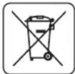
Do not dispose of electrically powered products with household wastes, they should be utilized in proper plants. Obtain information on wastes utilization from your seller or local authorities. Used up electric and electronic equipment contains substances active in natural environment. Unrecycled equipment constitutes a potential risk for environment and human health.
* Right to introduce changes is reserved.
"Grupa Topex Spółka z ograniczoną odpowiedzialnością" Spółka komandytowa with seat in Warsaw at ul. Pograniczna 2/4 (hereinafter Grupa Topex) informs, that all copyrights to this instruction (hereinafter Instruction), including, but not limited to, text, photographs, schemes, drawings and layout of the instruction, belong to Grupa Topex exclusively and are protected by laws accordingly to Copyright and Related Rights Act of 4 February 2004 (ustawa o prawie autorskim i prawach pokrewnych, Dz. U. 2006 No 90 item 631 with later amendments). Copying, processing, publishing, modifications for commercial purposes of the entire Instruction or its parts without written permission of Grupa Topex are strictly forbidden and may cause civil and legal liability.
1

natural_image
Icon of a person reading a book inside a circle (no text or symbols)2

natural_image
Simple icon of a person wearing headphones and sunglasses (no text or symbols)3

natural_image
Weather symbol with cloud and raindrops (no text)4

natural_image
Simple geometric diagram with two concentric squares (no text or symbols)5
1

natural_image
Icon of a person using a laptop inside a circle (no text or symbols)2

natural_image
Simple icon of a person wearing headphones and sunglasses (no text or symbols)3

natural_image
Weather symbol with cloud and raindrops (no text)4

natural_image
Simple geometric diagram with two concentric squares (no text or symbols)5
1

natural_image
Icon of a person using a computer (no text or symbols)2

natural_image
Simple icon of a person wearing headphones and sunglasses (no text or symbols)3

natural_image
Weather symbol with cloud and raindrops (no text)4

natural_image
Simple geometric diagram with two concentric squares (no text or symbols)5
1

natural_image
Icon of a person using a laptop inside a circle (no text or symbols)2

natural_image
Simple icon of a person wearing headphones and sunglasses (no text or symbols)3

natural_image
Weather symbol with cloud and raindrops (no text)4

natural_image
Simple geometric diagram with two concentric squares (no text or symbols)5
1

natural_image
Icon of a person using a book inside a circle (no text or symbols)2

natural_image
Simple icon of a person wearing headphones and sunglasses (no text or symbols)3

natural_image
Weather symbol with cloud and raindrops inside a prohibition sign (no text)4

natural_image
Simple geometric diagram with two concentric squares (no text or symbols)5
MONTÁŽ OHEBNÉ HNACÍ HŘÍDELE

1

natural_image
Icon of a person reading a book inside a circle (no text or symbols)2

natural_image
Simple icon of a person wearing headphones and sunglasses (no text or symbols)3

natural_image
Weather symbol with cloud and raindrops (no text)4

natural_image
Simple geometric diagram of two concentric squares (no text or symbols)5
1

natural_image
Icon of a person using a book inside a circle (no text or symbols)2

natural_image
Simple icon of a person wearing headphones and sunglasses (no text or symbols)3

natural_image
Weather symbol with cloud and raindrops inside a prohibition sign (no text)4

natural_image
Simple geometric diagram with two concentric squares (no text or symbols)5
1

natural_image
Icon of a person using a laptop inside a circle (no text or symbols)2

natural_image
Simple black-and-white icon of a person wearing headphones and sunglasses (no text or symbols)3

natural_image
Weather symbol with cloud and raindrops (no text)4

natural_image
Simple geometric diagram of two concentric squares (no text or symbols)5
1

natural_image
Icon of a person reading a book inside a circle (no text or symbols)2

natural_image
Simple icon of a person wearing headphones and sunglasses (no text or symbols)3

natural_image
Weather symbol with no text, featuring a cloud and raindrops inside a circle (no text)4

natural_image
Simple geometric diagram with two concentric squares (no text or symbols)5
1

natural_image
Icon of a person reading a book inside a circle (no text or symbols)2

natural_image
Simple icon of a person wearing headphones and sunglasses (no text or symbols)3

natural_image
Weather symbol with cloud and raindrops inside a prohibition sign (no text)4

natural_image
Simple geometric diagram with two concentric squares (no text or symbols)5
1

natural_image
Icon of a person reading a book inside a circle (no text or symbols)2

natural_image
Simple black-and-white icon of a person wearing headphones and sunglasses (no text or symbols)3

natural_image
Weather symbol with cloud and raindrops (no text)4

natural_image
Simple geometric diagram with two concentric squares (no text or symbols)5
1

natural_image
Icon of a person using a laptop inside a circle (no text or symbols)2

natural_image
Simple icon of a person wearing headphones and sunglasses (no text or symbols)3

natural_image
Weather symbol with cloud and raindrops (no text)4

natural_image
Simple geometric diagram with two concentric squares (no text or symbols)5
- Pozor, budite posebno oprezni.
- Pročitajte upute za upotrebu, poštujte upozorenja i sigurnosne uvjete koje su u njima navedene!
- Koristite sredstva individualne zaštite (zaštitne gogle, antifone)
- Štitite od kiše
- Druga klasa druga zaštite
KONSTRUKCIJA I NAMJENA
1

natural_image
Icon of a person reading a book inside a circle (no text or symbols)2

natural_image
Simple icon of a person wearing headphones and sunglasses (no text or symbols)3

natural_image
Weather symbol with cloud and raindrops inside a prohibition sign (no text)4

natural_image
Simple geometric diagram with two concentric squares (no text or symbols)5
1

natural_image
Icon of a person using a laptop inside a circle (no text or symbols)2

natural_image
Simple icon of a person wearing headphones and sunglasses (no text or symbols)3

natural_image
Weather symbol with cloud and raindrops (no text)4

natural_image
Simple geometric diagram of two concentric squares (no text or symbols)5
1

natural_image
Icon of a person reading a book inside a circle (no text or symbols)2

natural_image
Simple icon of a person wearing headphones and sunglasses (no text or symbols)3

natural_image
Weather symbol with cloud and raindrops (no text)4

natural_image
Simple geometric diagram of two concentric squares (no text or symbols)5
1

natural_image
Icon of a person reading a book inside a circle (no text or symbols)2

natural_image
Simple icon of a person wearing headphones and sunglasses (no text or symbols)3

natural_image
Weather symbol with cloud and raindrops (no text)4

natural_image
Simple geometric diagram of two concentric squares (no text or symbols)5
- MINISZLIFIERKA
- 59G019
- DETAILED SAFETY REGULATIONS
- MINIGRINDER. SAFETY WARNINGS
- GRAPHITE
- KICK BACK AND RELEVANT SAFETY TIPS
- SPECIAL SAFETY DIRECTIONS FOR GRINDING AND CUTTING WITH GRINDING WHEEL
- SPECIAL SAFETY DIRECTIONS FOR WORKING WITH WIRE BRUSHES
- ADDITIONAL SAFETY PRECAUTIONS
- EXPLANATION OF USED SYMBOLS
- CONSTRUCTION AND USE
- Inappropriate use.
- DESCRIPTION OF DRAWING PAGES
- MEANING OF SYMBOLS
- EQUIPMENT AND ACCESSORIES
- INSTALLATION AND REMOVAL OF COLLET SLEEVE CAP
- Disconnect the minigrinder from power supply.
- REPLACEMENT OF COLLET SLEEVE
- INSTALLATION AND REPLACEMENT OF ACCESORIES
- INSTALLATION OF FLEXIBLE DRIVE SHAFT
- INSTALLATION AND REPLACEMENT OF ACCESSORIES IN FLEXIBLE SHAFT HOLDER
- SWITCHING ON / SWITCHING OFF
- ADJUSTMENT OF SPINDLE ROTATIONAL SPEED
- RECOMMENDED ROTATIONAL SPEEDS FOR MINIGRINDER OPERATION
- CUTTING
- GRINDING
- MAINTENANCE AND STORAGE
- REPLACEMENT OF CARBON BRUSHES
- SPECIFICATIONS
- NOISE AND VIBRATION DATA
- Information regarding noise and vibration
- ENVIRONMENT PROTECTION
- MONTÁŽ OHEBNÉ HNACÍ HŘÍDELE
- KONSTRUKCIJA I NAMJENA
Brand : Graphite
Model : 59G019
Category : Uncategorized