
J-HANDLE KIT 125 L - Gardening Equipment HUSQVARNA - Free user manual and instructions
Find the device manual for free J-HANDLE KIT 125 L HUSQVARNA in PDF.

| Product type | J-Handle kit for brushcutter |
| Brand | HUSQVARNA |
| Model | J-HANDLE KIT 125 L |
| Category | Garden equipment |
| Included components | Ring handle, clamping plate, bolt, wing nut, J-handle, 2 screws, suspension eyelet, 2 screws, harness, weed blade, ground guard bowl, support flange, nut, transport protection device, blade nut wrench |
| Compatible use | Specific Husqvarna trimmers (see machine technical specifications) |
| Cutting equipment type | Grass blade, grass knives, weed head, plastic knives |
| Clearing blade | Not compatible with the J-handle |
| Required guard | Approved blade guard (ref. according to model) |
| Working methods | Brushing (tall and thick grass), weeding (edges of paths and around trees) |
| Safety | Use approved ear protectors and goggles, maintain a safety distance of 15 m, stop the engine before cleaning or unclogging |
| Maintenance | Check for cracks on blade, support flange, lock nut, blade guard; replace if damaged |
| Sharpening | With a single-cut flat file, file the cutting edges evenly to preserve balance |
| Blade nut tightening | 35-50 Nm (3.5-5 kgm), left-hand thread |
| Technical specifications | Blade shaft thread M10, central hole of blades/knives Ø 25.4 mm |
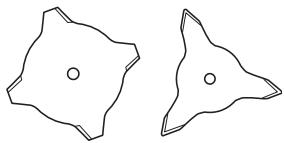
| Approved accessories | Grass blade 255-4 1" (Ø 255, 4 teeth), Weed head T25, Tricut knives Ø 300 mm, Fixed ground guard bowl |
Frequently Asked Questions - J-HANDLE KIT 125 L HUSQVARNA
User questions about J-HANDLE KIT 125 L HUSQVARNA
0 question about this device. Answer the ones you know or ask your own.
Ask a new question about this device
Download the instructions for your Gardening Equipment in PDF format for free! Find your manual J-HANDLE KIT 125 L - HUSQVARNA and take your electronic device back in hand. On this page are published all the documents necessary for the use of your device. J-HANDLE KIT 125 L by HUSQVARNA.
USER MANUAL J-HANDLE KIT 125 L HUSQVARNA
Note the following before starting: 26
WHAT IS WHAT?
What is what?
SAFETY INSTRUCTIONS
Cutting equipment 28
Sharpening grass cutters and grass blades 28
General working instructions 28
ASSEMBLY
Fitting the J-handle 30
Fitting the suspension ring 30
Fitting the blade guard/combination guard, grass blade and grass cutter 30
Assembling the cutting equipment 30
STARTING AND STOPPING
Check before starting 31
TECHNICAL DATA
Technical data 31
Note the following before starting:
Please read the operator's manual carefully and make sure you understand the instructions before using the machine. These instructions supplement the instructions that were included with the machine. For other procedures, please refer to the operating instructions for the machine.
Husqvarna AB has a policy of continuous product development and therefore reserves the right to modify the design and appearance of products without prior notice.
Long-term exposure to noise can result in permanent hearing impairment. So always use approved hearing protection.

WARNING! Under no circumstances may the design of the machine be modified without the permission of the manufacturer. Always use genuine accessories. Non-authorized modifications and/or accessories can result in serious personal injury or the death of the operator or others.

WARNING! This accessory may only be used together with the intended trimmer, see under heading "Approved accessories" in chapter Technical data in the machine's Operator's Manual.

WARNING! Only grass blades/grass cutters or trimmer heads/plastic blades may be used when the J-handle is fitted. Saw blades must never be used with the J-handle.
IMPORTANT! Never use a cutting attachment without an approved guard. See the chapter on Technical data. If an incorrect or faulty guard is fitted this can cause serious personal injury.
IMPORTANT! Wear boots with steel toe-caps and non-slip sole if a grass blade is fitted to the machine.
The J-handle set contains the following parts:
Loop handle
1 Loop handle
1 securing plate
1 bolt
1wingnut
J-handle
1J-handle
2 screws
1 harness
1 suspension ring
2 screws
1 grass blade
1 support cup
1 support flange
1 nut
1 socket spanner
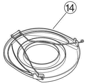
1 transport guard
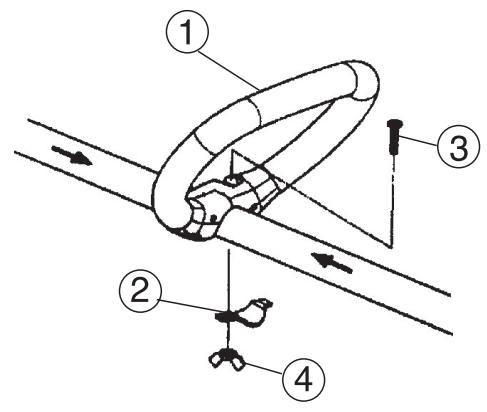
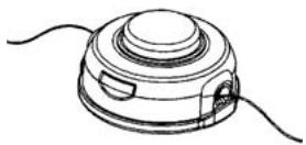
What is what?
1 Loop handle
2 Securing plate
3 Bolt
4 Wing nut
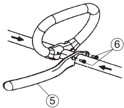
5 J-handle
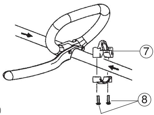
6 2 screws
7 Suspension ring
8 2 screws
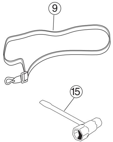
9 Harness
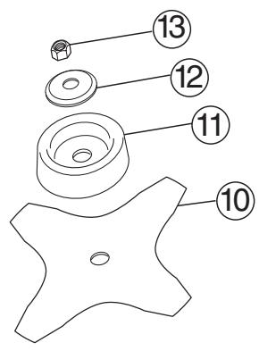
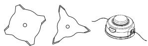
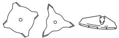
10 Grass blade
11 Support cup
12 Support flange
13 Nut
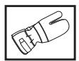
14 Transport guard
15 Socket spanner
Cutting equipment
This section describes how to choose and maintain your cutting equipment in order to:
- Reduce the risk of kickback.
- Obtain maximum cutting performance.
- Extend the life of cutting equipment.
General rules
1 Only use cutting attachments with the guards we recommend! See the chapter on Technical data.
2 Maintain the correct blade setting! Follow our instructions and use the recommended blade setting tool. An incorrectly set blade increases the risk of jamming and kickback.
3 Check the cutting attachment for damage or cracks. A damaged cutting attachment should always be replaced.

WARNING! Using an incorrect cutting attachment or an incorrectly sharpened blade increases the risk of kickback.

WARNING! Avoid cutting with the area of the blade between the 12 o'clock and 3 o'clock positions. Because of the speed of rotation of the blade kickback can occur if you attempt to cut thick stems with this area of the blade.
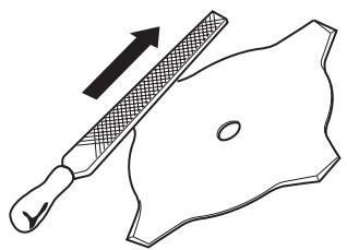
Sharpening grass cutters and grass blades

- See the cutting attachment packaging for correct sharpening instructions. Sharpen blades and cutters using a single-cut flat file.
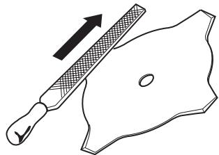
- Sharpen all edges equally to maintain blade balance.

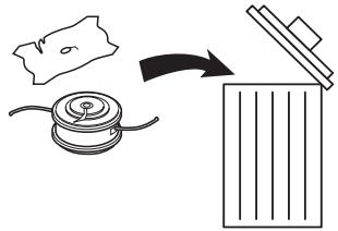
WARNING! Always discard a blade that is bent, twisted, cracked, broken or damaged in any other way. Never attempt to straighten a twisted blade so that it can be reused. Only use original blades of the specified type.
General working instructions
Always carry out clearing and trimming at full throttle.
- Always slow the engine to idle speed after each working operation. Long periods at full throttle without any load on the engine (i.e. without the resistance that the cutting attachment exerts on the engine when you are using the machine) can lead to serious engine damage.
Terms
- Brush cutting is a general term for clearing grass. Grass blades and grass cutters are used for this purpose.
- Grass trimming is a general term for light clearing, e.g. around edges or around trees. A trimmer head or plastic blades are used.

WARNING! Sometimes branches or grass get caught between the guard and cutting attachment. Always stop the engine before cleaning.
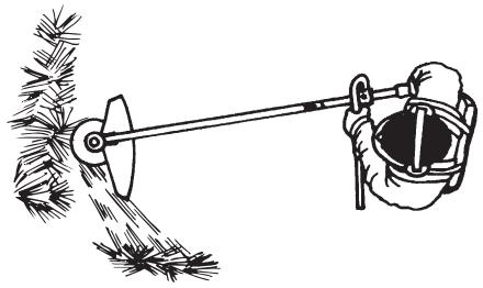
Grass clearing using a grass blade

- Grass blades and grass cutters must not be used on woody stems.
- A grass blade is used for all types of tall or coarse grass.
- The grass is cut down with a sideways, swinging movement, where the movement from right-to-left is the clearing stroke and the movement from left-to-right is the return stroke. Let the left-hand side of the blade (between 8 and 12 o'clock) do the cutting.
- If the blade is angled to the left when clearing grass, the grass will collect in a line, which makes it easier to collect, e.g. by raking.
- Try to work rhythmically. Stand firmly with your feet apart. Move forward after the return stroke and stand firmly again.
- Let the support cup rest lightly against the ground. It is used to protect the blade from hitting the ground.
- Reduce the risk of material wrapping around the blade by following these instructions:
1 Always work at full throttle.
2 Avoid the previously cut material during the return stroke.
- Stop the engine, unclip the harness and place the machine on the ground before you start to collect the cut material.

WARNING! Neither the operator of the machine nor anyone else may attempt to remove the cut material while the engine is running or the cutting equipment is rotating, as this can result in serious injury.
Stop the engine and cutting equipment before you remove material that has wound around the blade shaft as otherwise there is a risk of injury.

WARNING! Watch out for thrown objects. Always wear approved eye protection. Never lean over the cutting attachment guard. Stones, rubbish, etc. can be thrown up into the eyes causing blindness or serious injury.
Keep unauthorised persons at a distance. Children, animals, onlookers and helpers should be kept outside the safety zone of 15 m. Stop the machine immediately if anyone approaches.
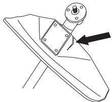
Fitting the J-handle

WARNING! Only grass blades/grass cutters or trimmer heads/plastic blades may be used when the J-handle is fitted. Saw blades must never be used with the J-handle.
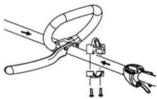
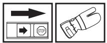
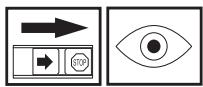
- Clip the loop handle onto the shaft. Note that the loop handle must be fitted between the arrows on the shaft.
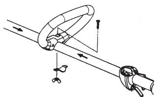
- Fit the bolt, securing plate and wing nut as shown in the diagram.
- Attach the J-handle to the loop handle using the two screws, as shown.
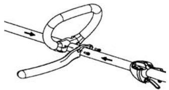
Make a final adjustment of the J-handle to give a comfortable working position. Tighten the knob.
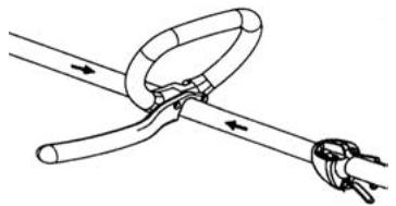
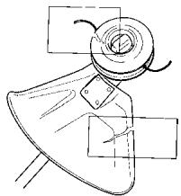
Fitting the suspension ring
Fit the suspension ring between the rear handle and the loop handle. Position the hanging ring so that the machine is balanced and comfortable to work with.
Fitting the blade guard/combination guard, grass blade and grass cutter
- Hook the blade guard/combination guard (A) onto the fitting on the shaft and secure with the bolt. CAUTION! Use the recommended blade guard. See the Technical data section.
- Fit the drive disc (B) on the output shaft.
-
Turn the blade shaft until one of the holes in the drive disc aligns with the corresponding hole in the gear housing.
-
Insert the locking pin (C) in the hole to lock the shaft.
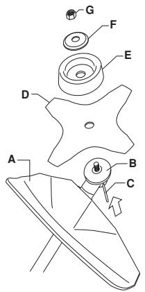
- Place the blade (D), support cup (E) and support flange (F) on the output shaft.
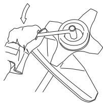
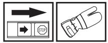
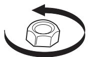
- Fit the nut (G). The nut must be tightened to a torque of 35 - 50 Nm (3.5-5 kpm). Use the socket spanner in the tool kit. Hold the shaft of the spanner as close to the blade guard as possible. To tighten the nut, turn the spanner in the opposite direction to the direction of rotation (Caution! left-hand thread).
Assembling the cutting equipment

WARNING!
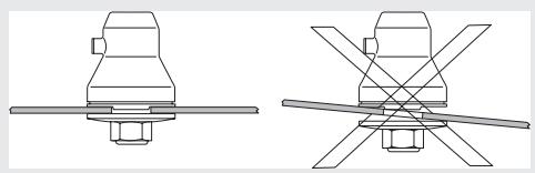
When fitting the cutting attachment it is extremely important that the raised section on the drive disc/support flange engages correctly in the centre hole of the cutting attachment. If the cutting attachment is fitted incorrectly it can result in serious and/or fatal personal injury.

WARNING! Never use a cutting attachment without an approved guard. See the chapter on Technical data. If an incorrect or faulty guard is fitted this can cause serious personal injury.
Check before starting
For safety reasons follow these recommendations!
- Check the blade to ensure that no cracks have formed at the bottom of the teeth or by the centre hole. The most common reason why cracks are formed is that sharp corners have been formed at the bottom of the teeth while sharpening or that the blade has been used with dull teeth. Discard a blade if cracks are found.
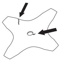
- Check that the support flange is not cracked due to fatigue or due to being tightened too much. Discard the support flange if it is cracked.
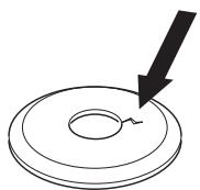
- Ensure the locking nut has not lost its captive force. The nut lock should have a locking force of at least 1.5 Nm . The tightening torque of the locking nut should be 35-50 Nm.
- Check that the blade guard is not damaged or cracked. Replace the blade guard if it is exposed to impact or is cracked.
- Check that the trimmer head and trimmer guard are not damaged or cracked. Replace the trimmer head or trimmer guard if they have been exposed to impact or are cracked.
- Never use the machine without a guard nor with a defective guard.
- All covers must be correctly fitted and undamaged before you start the machine.
Technical data
| Approved accessories | ||
| Blade shaft thread M10 | ||
| Centre hole in blades/cutters, Ø 25,4 mm | ||
| Terms | Type | Cutting attachment guard, Art. no. |
| Grass blade/grass cutter | Grass 255-4 1" (Ø 255 4-teeth) | 503 93 42-02 |
| Trimmer head | T25 | 537 33 83-02 |
| Plastic blades | Tricut Ø 300 mm | 531 00 38-11 |
| Support cup | Fixed | |
Sommaire
SOMMAIRE
Sommaire 32
GIVENLIK ACIKLAMALARI
Kesici gereçler 76