PVKO 50 C3 - Compressor PARKSIDE - Free user manual and instructions
Find the device manual for free PVKO 50 C3 PARKSIDE in PDF.

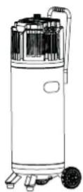
| Product type | Vertical compressor |
| Brand | Parkside |
| Model | PVKO 50 C3 |
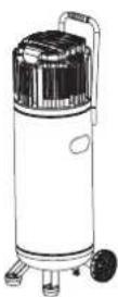
| Dimensions (L x W x H) | 330 x 310 x 1060 mm |
| Weight | 23.8 kg |
| Power supply | 230 V~, 50 Hz, 1500 W |
| Tank capacity | 50 L |
| Maximum pressure | 10 bar |
| Adjustable pressure | 0 – 10 bar |
| Operating mode | S3 25% (2.5 min on / 7.5 min off) |
| Intake flow rate (theoretical) | 240 L/min |
| Output flow rate (theoretical) | 140 L/min |
| Maximum speed | 4000 min⁻¹ |
| Protection rating | IP30 |
| Sound pressure level | LpA = 74 dB(A); KpA = 1.94 dB |
| Guaranteed sound power level | 96 dB(A) |
| Hose length | 5 m |
| Hose max pressure | 10 bar (at 23 °C) |
| Max pressure of tire pressure gauge | 8 bar |
| Package contents | Compressor, 2 wheels, 2 feet, 5 m spiral hose, tire pressure gauge, 3 adapters, extension nozzle, mounting material, manual |
| Intended use | Powering compressed air tools (blowing, screwing, stapling, painting); inflating bicycle tires, inflatable boats, mattresses, balls |
| Safety | Safety valve set at 10 bar, on/off switch, rain protection (IPX0) |
| Maintenance | Drain condensation water after each use (at least once a week); regularly check the tank |
| Warranty | 3 years (Belgium) / Statutory warranty (France) |
Frequently Asked Questions - PVKO 50 C3 PARKSIDE
User questions about PVKO 50 C3 PARKSIDE
0 question about this device. Answer the ones you know or ask your own.
Ask a new question about this device
Download the instructions for your Compressor in PDF format for free! Find your manual PVKO 50 C3 - PARKSIDE and take your electronic device back in hand. On this page are published all the documents necessary for the use of your device. PVKO 50 C3 by PARKSIDE.
USER MANUAL PVKO 50 C3 PARKSIDE
VERTICAL COMPRESSOR PVKO 50 C3 VERTIKALER KOMPRESSOR PVKO 50 C3 COMPRESSEUR VERTICAL PVKO 50 C3

IE CYGB NI MT
VERTICAL COMPRESSOR
Translation of the original instructions
BEFR CH
COMPRESSEUR VERTICAL
Before reading, fold out the page with the images and familiarise yourself with all the features of the device.
DEATCH
GB/IE/NI/CY/MT Translation of the original instructions Page 5
| DE/AT/CH Originalbetriebsanleitung Seite 17 | |||
| FR/BE/CH Traduction des instructions d'origine | Page 31 | ||
| NL/BE | Vertaling van de originele instructies | Pagina | 45 |
| CZ | Překlad původního návodu | Strana | 59 |
| PL | Tłumaczenie oryginalnej instrukcji | Strona | 71 |
| SK | Preklad pôvodného návodu | Strana | 85 |
| ES | Traducción de las instrucciones originales | Página | 97 |
| DK | Oversættelse af den originale vejledning | Side | 111 |
| IT/MT/CH | Traduzione delle istruzioni originali | Pagina | 123 |
| HU | Az eredeti utasítások fordítása | Oldal | 137 |
    |  |
  | |
1. Introduction ...6.
1.1 Intended use . 6
1.2 Scope of delivery .6
1.3 Features 6
1.4 Technical data 7
1.4.1 Compressor 7
1.4.2 Spiral hose...7
1.4.3 Pneumatic tyre inflation gauge ...7
2. Safety information ...8
2.1 General safety instructions for power tools 8
2.2 Additional safety information 9
2.3 Safety instructions for the supplied pneumatic hose ...10
2.4 General safety rules for the tyre inflation gauge ...10.
2.5 Operation of a pressure vessel (according to Pressure Equipment Directive)....10....
2.6 Residual risks 11
3. Compressor operation
3.1 Before first use 11
3.1.1 Mounting the feet 11
3.1.2 Mounting the wheels 11
3.1.3 Setting up the device 11
3.2 First use 11
3.2.1 Switching on/off 11
3.2.2 Air pressure presets 11
3.2.3 Setting the air pressure 11
3.2.4 Safety valve 12
3.2.5 Draining condensation 12
3.2.6 Releasing overpressure (adjusting pressure) 12
4. Operating the pneumatic hose
5. Operating the pneumatic tyre inflation gauge
5.1 Before first use 12
5.2 First use 12
5.2.1 Without adapter 13
5.2.2 With valve adapter, ball needle, universal adapter 13
5.2.3 With extension nozzle 13
6. Cleaning, maintenance, transport and storage by the user
6.1 Safety measures 13
6.2 Maintenance of the pressure vessel 14
6.3 Cleaning 14
6.4 Transport 14
6.5 Storage 14
6.6 Troubleshooting 14
7. Disposal
7.1 Environmental compatibility and material disposal 15
8. ROWI Germany GmbH Warranty
9. Service
10. Translation of the original declaration of conformity C€
VERTICAL COMPRESSOR PVKO 50 C3
1. Introduction
Congratulations on the purchase of your new device. You have thus chosen a high-quality product. The manual is part of this product. It contains important instructions for safety, use and disposal. Familiarise yourself with all operating and safety instructions before using the product. Only use the product as described and for the specified areas of application. Hand over all documents when passing the product on to third parties.
1.1 Intended use
The compressor is used to operate pneumatic tools in the home workshop. It is designed to draw in and compress clean, dust-free, dry and uncontaminated ambient air. The ambient air must not contain any aggressive or flammable admixtures. The compressor may only be used in closed spaces with sufficient ventilation. Pneumatic tools can be connected to the compressor and used for blowing, screwing, tacking and varnishing. Read the relevant manual for the correct use of these pneumatic tools. The compressor and the connected pneumatic tools may only be operated by a trained person. For persons with limited physical, sensory or mental abilities as well as children and adolescents, operating the compressor and connected pneumatic tools is prohibited. Intended use also includes compliance with all the information in this manual.
In connection with a compressor, the pneumatic hose is used to supply pneumatic tools with energy. The pneumatic hose is exclusively meant for the transport of compressed air. It is not suitable for transporting liquids or gases such as oxygen.
The pneumatic tyre inflation gauge is suitable for inflating bicycle tyres, inflatable boats, air mattresses, balls, etc. The device can be used to measure pressure and release compressed air. The device is NOT suitable for inflating car tyres.
Any other use or modification of the products is considered improper and involves considerable risk of accidents. We accept no liability for damage resulting from improper use. The products are intended for private use only and may not be used commercially or industrially.
1.2 Scope of delivery
1 Compressor
2x Wheels
2x Feet
Assembly material:
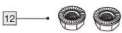
4x Flange nut
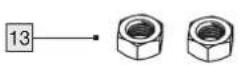
2x Nut
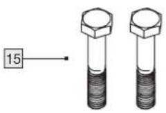
2x Wheel bolts
2x Washer
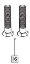
2x Hexagon head screws
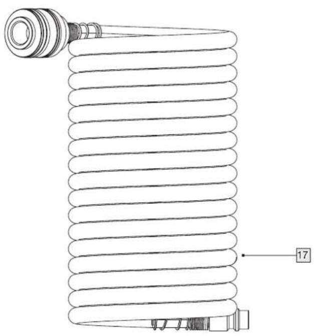
1x Spiral hose, 5m
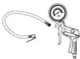
1x Pneumatic tyre inflation gauge
3x Valve adapter
■ 1x Extension nozzle
1x Manual
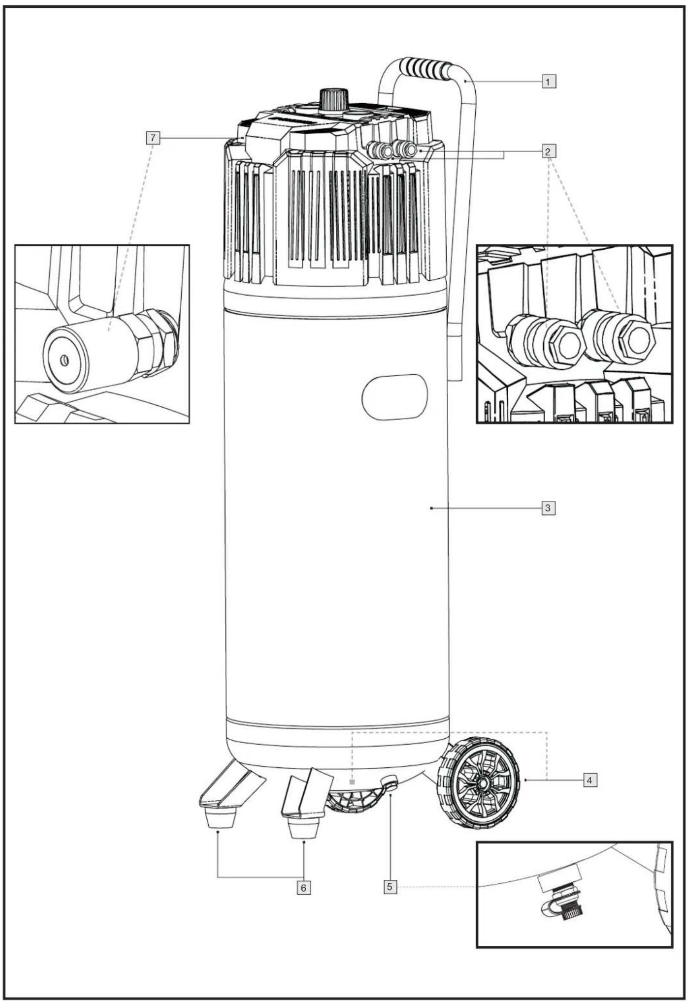
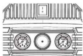
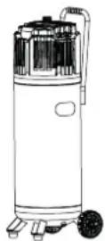
1.3 Features
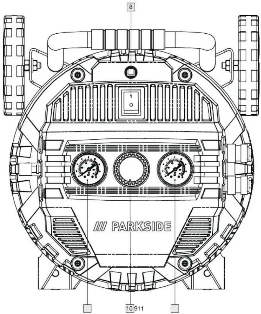
1 Transport handle
2 Quick coupling (for the hose connector)
3 Pressure vessel (tank)
4 Wheels
5 Drain plug (for condensation)
6 Feet
7 Safety valve
8 On/off switch
9 Pressure gauge (output pressure)
10 Pressure regulator
11 Pressure gauge (vessel pressure)
12 Flange nuts
13 Nuts
14 Washers
15 Wheel bolts
16 Hexagon head screws
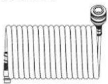
17 Spiral hose (pneumatic hose)
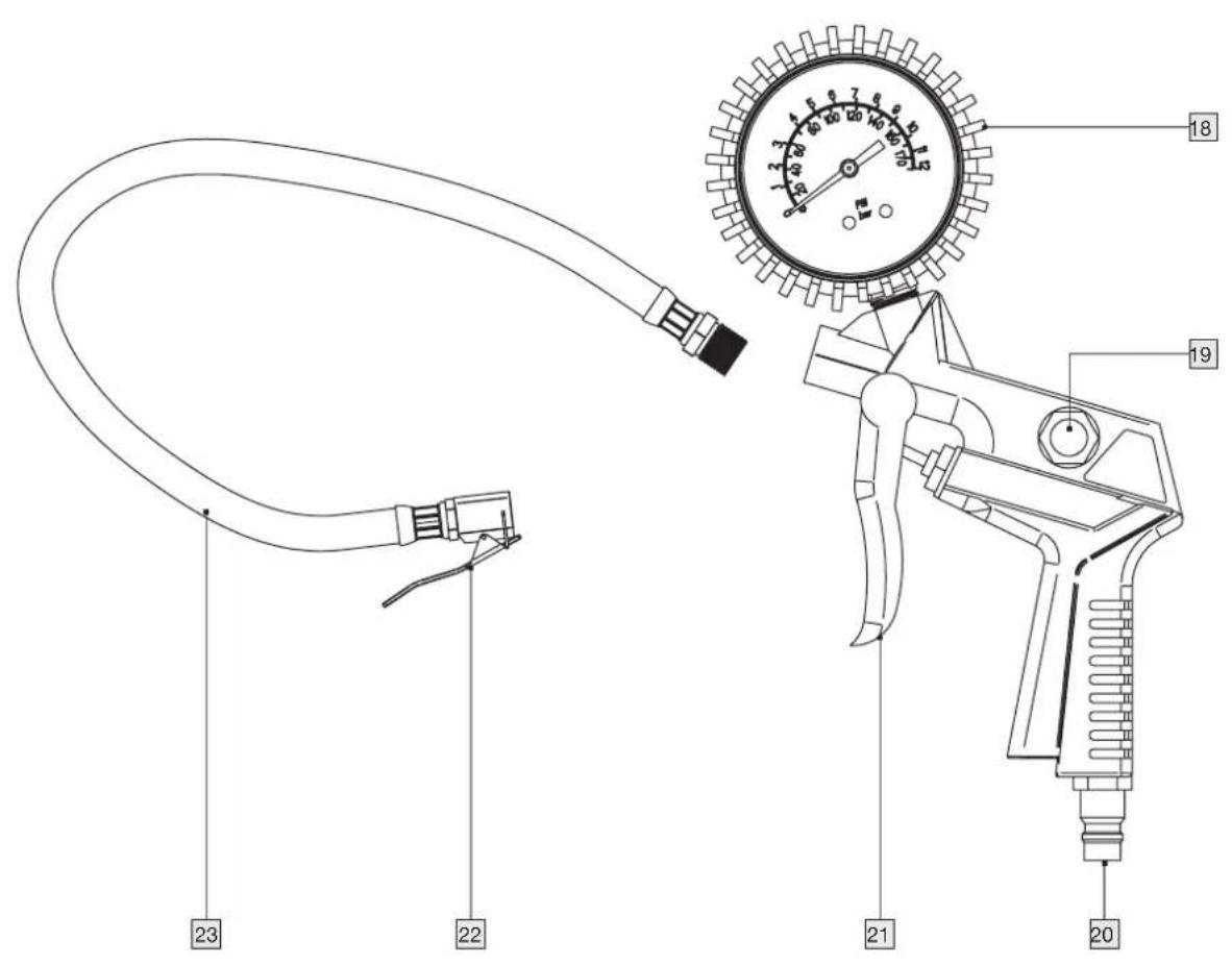
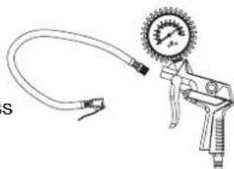
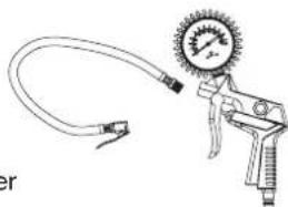
18 Pressure gauge
19 Drain valve
20 Connector plug
21 Trigger
22 Quick-release lever
23 Hose with quick-release lever
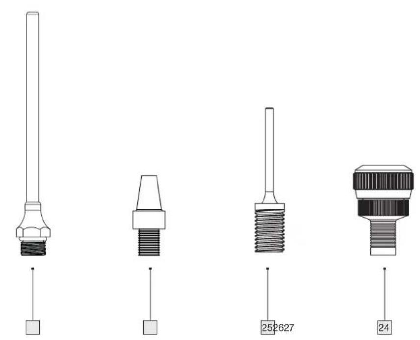
24 Valve adapter
25 Ball pin
26 Universal adapter
27 Extension nozzle
natural_image
Technical line drawing of a mechanical component with three circular gauges (no text or symbols)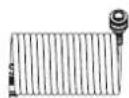

natural_image
Line drawing of a pressure gauge tool with attached tubing (no text or symbols)1.4 Technical data
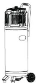
1.4.1 Compressor
Rated voltage: 230 V \~ 50 Hz
Rated power: 1500 W
Mode of operation: S3 25%*

Highest speed of the compressor: 4000 min -1 Pressure vessel volume: 50 l

Permissible maximum pressure: max. 10 bar Theo. Suction capacity approx. 240 l/min Theo. Output approx. 140 l/min

Protection class: IP30**

Dimensions: 330 x 310 x 1060 mm total mass (without cable and accessories): 23,8 kg
* This means that the compressor may be operated for 2.5 minutes within a 10-minute period and must cool down again for the remaining 7.5 minutes (at an ambient temperature of 20^ ).
** IP3X: Protection against ingress of foreign bodies ∅ > 2.5 mm. Keep tools and wires away.
IPX0: No protection from water, i.e. the device must not be used in damp or wet spaces or in the rain.
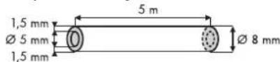
1.4.2 Spiral hose
Max. Working pressure: 10 bar (at 23 °C)
6.5 bar (at 50 °C)
Hose type: middle area of application
Hose outer diameter: ∅ 8.0 mm
Hose inner diameter: ∅ 5.0 mm
Wall thickness: 1.5 mm
Coupling: DN 7.2/6 mm
Connection: 14 " (6.35 mm)
Length: 5 m
Applicable
temperature range: -10 °C to + 50 °C
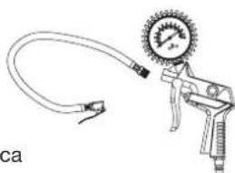
1.4.3 Pneumatic tyre inflation gauge
Working pressure: max. 8 bar
Compressed air quality: cleaned, oil-free and condensate-free
Volume flow: 40-70 l/min
NAMEPLATE

BADGE
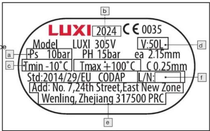
a) maximum operating pressure (hp in bar);
b) maximum operating temperature (Tmax in °C);
c) minimum operating temperature (Tmin in °C);
d) capacity of the vessel (V in L);
e) name, registered trade name or registered trademark and address of the manufacturer;
f) type identification and serial or batch identification of the vessel.
Explanations of all symbols found on the product
| WARNING! | WARNINGRead the manual before use. |
 | Manual must be read. |
 | Do not expose the machine to rain. The device may only be stationed, stored and operated under dry ambient conditions. |
 | Risk of high temperatures |
 | Compressor unit may start without warning. |
 | Protection class |
 | Do not open the valve before the air hose is connected. |
 | Do not leave device on |
 | Wear eye protection |
 | Wear respiratory protection |
 | Wear ear protection |
 | Wear protective gloves |
 | Guaranteed sound power level |
Noise emission values
Sound pressure level L_pA = 74 dB (A)
Uncertainty K_pA = 1.94 dB
Sound power level L_WA = 94 dB (A)
Uncertainty K_WA = 1.94 dB
Guaranteed sound power level: 96 dB (A)
Wear ear protection!
NOTE
- The noise level specified in these instructions has been measured according to a standardized measurement procedure and can be used for device comparison.
WARNING!
- Noise emissions during actual use of the device may differ from the specified values, depending on the way in which the device is used, in particular, what type of workpiece is being machined and what kind of accessory is being used.
2. Safety information
2.1 General safety instructions for power tools

WARNING Read all safety information, instructions, illustrations and technical data provided with this power tool. Failure to comply with the following instructions may result in electric shock, fire and/or serious injury.
KEEP ALL SAFETY INFORMATION AND INSTRUCTIONS FOR FUTURE REFERENCE.
The term “power tool” used in the safety instructions refers to mains-operated power tools (with mains lead) or battery-operated power tools (without mains lead).
1) Workshop safety
a) Keep your work area clean and well lit. Clutter or unlit work areas may lead to accidents.
b) Do not operate the power tool in an explosive environment where flammable liquids, gases or dusts are present. Power tools produce sparks that may ignite the dust or fumes.
c) Keep children and other persons away while using the power tool. Distraction may cause you to lose control of the power tool.
2) Electrical safety
a) The plug of the power tool must fit into the socket. The plug must not be modified in any way. Do not use adapter plugs together with earthed power tools. Unmodified plugs and matching sockets reduce the risk of electric shock.
b) Avoid body contact with earthed surfaces such as those of pipes, heaters, cookers and refrigerators. There is an increased risk of electric shock if your body is earthed.
c) Keep power tools away from rain or wet conditions. Water ingress into a power tool increases the risk of electric shock.
d) Do not misuse the power cord to carry or hang the power tool or to pull the plug out of the socket. Keep the connecting cable away from heat, oil, sharp edges or moving parts. Damaged or tangled connecting cables increase the risk of electric shock.
e) When working with a power tool outdoors, only use extension cords that are also suitable for outdoor use. Using an extension cord suitable for outdoor use reduces the risk of electric shock.
f) If operation of the power tool in a damp environment is unavoidable, use a residual current circuit breaker. Using a residual current circuit breaker reduces the risk of electric shock.
3) Safety of persons
a) Be attentive, watch what you are doing and use common sense when working with a power tool. Do not use a power tool when you are tired or under the influence of drugs, alcohol or medication. A moment of carelessness when using the power tool may result in serious injury.
b) Wear personal protective equipment and safety glasses always. Wearing personal protective equipment, such as a dust mask, non-slip safety shoes, hard hat or ear protection, depending on the type and use of the power tool, reduces the risk of injury.
c) Avoid unintentional operation. Make sure the power tool is switched off before connecting it to the power supply and/or battery, picking it up or carrying it. If you have your finger on the switch while carrying the power tool or connect the power tool to the power supply while it is switched on, accidents may result.
d) Remove adjustment tools or spanners before switching on the power tool. A tool or spanner lodged in a rotating part of the power tool may cause injury.
e) Avoid abnormal posture. Make sure you stand securely and keep your balance at all times. This gives you better control of the power tool in unexpected situations.
f) Wear appropriate clothing. Do not wear loose clothing or jewellery. Keep hair, clothing and gloves away from moving parts. Loose clothing, jewellery or long hair can be caught by moving parts.
g) If dust extraction and collection devices can be fitted, make sure they are connected and used correctly. Using a dust extractor can reduce hazards from dust.
h) Do not lull yourself into a false sense of security and do not ignore the safety rules for power tools, even if you are familiar with the power tool after using it many times. Careless action may lead to serious injury within a fraction of a second.
4) Use and handling of the power tool
a) Do not overload the power tool. Use the designated power tool for your work. With the right power tool, you will work better and safer in the specified power range.
b) Do not use a power tool whose switch is defective. A power tool that can no longer be switched on or off is dangerous and must be repaired.
c) Unplug the power tool and/or remove a detachable battery before making any device adjustments, changing insert tool parts or putting the power tool away. This precaution prevents the power tool from starting accidentally.
d) Keep power tools not in use out of the reach of children. Do not allow anyone to use the power tool who is not familiar with it or has not read these instructions. Power tools are dangerous when used by inexperienced persons.
e) Maintain power tools and insert tools with care. Check whether moving parts function properly and are not jammed, whether parts are broken or damaged in such a way that the function of the power tool is impaired. Have damaged parts repaired before using the power tool. Many accidents are caused by poorly maintained power tools.
f) Keep cutting tools sharp and clean. Carefully maintained cutting tools with sharp cutting edges jam less and are easier to control.
g) Use power tools, accessories, insert tools, etc. according to these instructions. Take into account the working conditions and the job to be done. Using power tools for applications other than those for which they are intended may lead to dangerous situations.
h) Keep handles and grip surfaces dry, clean and free from oil and grease. Slippery handles and grip surfaces do not allow safe operation and control of the power tool in unforeseen situations.
5) Service
a. Have your power tool repaired only by qualified personnel and only with original spare parts. This ensures that the safety of the power tool is maintained.
2.2 Additional safety information
- Do not expose the compressor to rain.
- When using spraying accessories (e.g. paint spray guns), keep your distance from the unit during filling. Do not spray in the direction of the compressor!
RECOMMENDATION
Use a residual current device (RCD) with a tripping current of 30 mA or less.
If the mains lead of this device is damaged, it must be replaced with a special connecting lead available from the manufacturer or its after-sales service.
- Observe accident prevention regulations. In addition to the information in this manual, the general safety and accident prevention regulations of the local authorities must be adhered to.
The manual must be kept in the immediate vicinity of the compressor at all times and must be available to the operating personnel.
WARNING!
The compressor must not be used in a potentially explosive atmosphere. Fireplaces, open lights or sparking machines must not be present or operated.
Do not eat, drink or smoke in areas where work is being done.
■ Use only in well-ventilated areas or provide local exhaust ventilation.
There is no protection against water, i.e. the device must not be used in damp or wet spaces or in the rain, or in spaces where there is paint and/or dust mist. Make sure that the device does not come into contact with water or moisture during operation or storage. Short-term outdoor use of the compressor in dry ambient conditions is permissible. This compressor must NOT be used to suck in flammable gases ex and/or paint and dust mists.
- Avoid contact with hot parts. Do not touch any hot parts on the device. Note that various components may store heat and thus still cause burns even after the device has been used.
■ Move the device only with the help of the transport handle provided.
2.3 Safety instructions for the supplied pneumatic hose
■ Compressed air can cause serious injury.
— When the machine is not in use, before replacing accessories or when carrying out repair work, always shut off the air supply, depressurise the air hose and disconnect the machine from the compressed air supply.
— Never direct the airflow towards yourself or other people.
- Hoses whipping around can cause serious injury. Therefore, always check that the hoses and their fasteners are undamaged and have not come loose.
- Cold air should be carried away from the hands.
- Never exceed the maximum working pressure of the pneumatic hose or that of the pneumatic tool used.
- Connect the pneumatic hose to compressed air lines only if it is certain that the maximum permissible working pressure is prevented from being exceeded (e.g. by a pressure reducer/pressure regulator).
- Use the pneumatic hose with compressed air only. It is not permitted to use the pneumatic hose with liquids.
Slips, trips and falls are major causes of workplace injuries. Be aware of surfaces that may have become slippery due to the use of the compressor and of tripping hazards caused by the pneumatic hose.
- When loosening the hose coupling, hold the coupling piece of the hose with your hand. This way you avoid injuries caused by the hose recoiling.
- Do not use media such as white spirit, butyl alcohol and methylene chloride in conjunction with the pneumatic hose. These media destroy the pneumatic hose.
- Never crush or kink the spiral hose. This may damage the spiral hose. Do not use damaged pneumatic hoses. Damaged pneumatic hoses may cause injuries.
2.4 General safety rules for the tyre inflation gauge
The safety information must be read and understood before setting up, operating, repairing or servicing the tyre inflation gauge and before working near it. If this is not the case, it can lead to serious physical injuries.
The tyre inflation gauge must only be set up, adjusted or used by suitably qualified and trained operators.
This tyre inflation gauge must not be modified. Changes may reduce the effectiveness of the safety measures and increase the risks for the operator.
The safety instructions must not be lost. Give it to the operator.
■ Never use damaged equipment.
- Check signs and inscriptions for completeness and legibility. The device must be inspected regularly to check that the machine is marked with the clearly legible ratings and markings required in this manual. The user must contact the manufacturer to obtain replacement plates if necessary.
The operator and maintenance personnel must be physically able to handle the size, mass and power of the machine.
■ Make sure your body is balanced and that you have secure footing.
In the event of an interruption in the power supply, release the trigger.
- Do not blow on people or clean clothes on the body with the tyre inflation gauge. Risk of injury!
2.5 Operation of a pressure vessel (according to Pressure Equipment Directive)
- Whoever operates a pressure vessel shall maintain it in proper condition, operate it properly, monitor it, carry out necessary repair work without delay and take the safety measures required by the circumstances.
- Supervisory authorities may order necessary monitoring measures in individual cases.
- A pressure vessel must not be operated if it has defects that endanger employees or third parties.
- The pressure vessel must be checked regularly for damage, e.g. rust. If you notice any damage, contact the service centre immediately.
2.6 Residual risks
Even if you operate this machine according to the instructions, there are always residual risks. The following hazards may occur in connection with the design and construction of this machine:
a) Lung damage if suitable respiratory protection is not worn.
b) Hearing damage if suitable ear protection is not worn.
c) Damage to health resulting from vibration emissions if the device is used for a long period of time or is not properly managed and maintained.
WARNING!
This machine generates an electromagnetic field during operation. This field may affect active or passive medical implants under certain circumstances. To reduce the risk of serious or fatal injury, we recommend that persons with medical implants consult their physician and the medical implant manufacturer before operating the machine.
3. Compressor operation
3.1 Before first use
Remove all packing material and transport locks from the device. Check that the package contents are complete and undamaged. If possible, keep the packaging until the warranty period has expired.
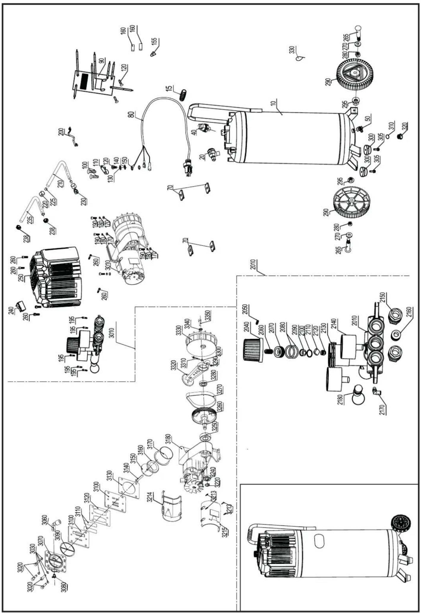
3.1.1 Mounting the feet
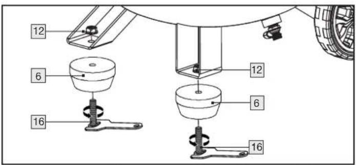
Mount the foot 6 with the hexagon head screw 16 and the flange nut 12 as shown in the illustration.
Repeat these steps to mount the second foot.
- An open-ended spanner is not included in the scope of delivery.
3.1.2 Mounting the wheels
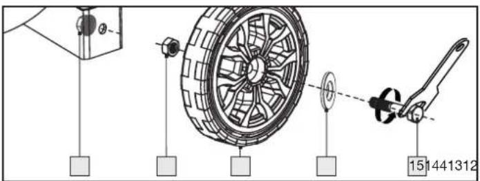
- Fit the wheel bolt 15 into the washer 14 then through the hole in the wheel 4.
- Tighten the nut 13 onto the wheel bolt 15. Make sure that the wheel 4 can still be turned on the screw.
■ Pass the wheel bolt 15 through the hole on the wheel linkage.
■ Fasten the wheel 4 with the flange nut 12.
Repeat these steps to mount the second wheel.
■ An open-end spanner is not included in the scope of delivery.
3.1.3 Setting up the device
For safe and correct operation of the device, the installation site must meet the following requirements:
The floor must be firm, flat and level. Do not place the device in a hot, wet or very humid environment or near combustible material.
The socket must be easily accessible so that the mains plug can be easily disconnected if necessary. The use of a cable extension is not recommended. Long supply cables can cause a voltage drop and thus prevent the motor from starting.
If you still have to use a cable extension, make sure that it is not longer than 5 m and that the cross-section is at least 1.5 mm ^2 . ALWAYS use the cable extension rolled out!
3.2 First use
READ THE MANUAL OF THE PNEUMATIC TOOL BEFORE CONNECTING IT TO THE COMPRESSOR!
Make sure the on/off switch 8 is "0". Now connect the compressor to an earthed socket protected by a residual current circuit breaker.
3.2.1 Switching on/off

Press the on/off switch 8 to the "I" position. The compressor is switched on.
- To switch off the compressor, press the on/off switch 8 to the "0" position.
3.2.2 Air pressure presets
The following pressures are preset:
- Switch-on pressure: approx. 8 bar
- Cut-off pressure: approx. 10 bar
3.2.3 Setting the air pressure
The pressure gauge shows the current pressure in the pressure vessel 3.
With the pressure regulation you can set the desired pressure (0 -10 bar). Pay attention to the nameplate of the pneumatic tool to be connected!

- You can read off the actual pressure delivered on the right-hand pressure gauge ⑨. This is delivered at the two quick couplings ②.
3.2.4 Safety valve
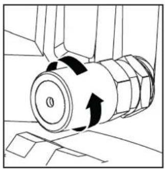
natural_image
Technical line drawing of a mechanical component with directional arrows indicating motion (no text or symbols)- Thesafetyvalve 7 is set to the maximum permissible pressure of the pressure vessel 3. It is not permitted to adjust the safety valve 7 or remove the connection lock between the drain nut and its cap.
Turn the drain nut counterclockwise to open the safety valve 7 outlet.
■ The safety valve 7 now audibly releases air. Then retighten the drain nut clockwise.
NOTE
Repeat this process every 30 operating hours or at least three times a year.
3.2.5 Draining condensation
Condensation collects at the bottom of the tank 3.
- Open the drain plug 5 on the underside of the tank completely ∅.
- Tilt the compressor to the side so that the drain plug 5 is at the lowest point of the tank 3 and wait until condensation has drained completely.
■ Then close the drain plug 5 again.
CAUTION
Condensation must only be drained when the tank 3 is NOT under pressure.
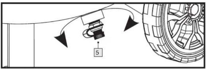
natural_image
Diagram of a mechanical assembly with a component and directional arrows, no readable text or symbols present.NOTE
Drain condensation after each operation, but at least once a week. To do this, tilt the compressor to the side of the valve so that the condensation can drain completely.
3.2.6 Releasing overpressure (adjusting pressure)
■ Switch off the compressor.
■ Use the overpressure with an idle pneumatic tool.
4. Operating the pneumatic hose
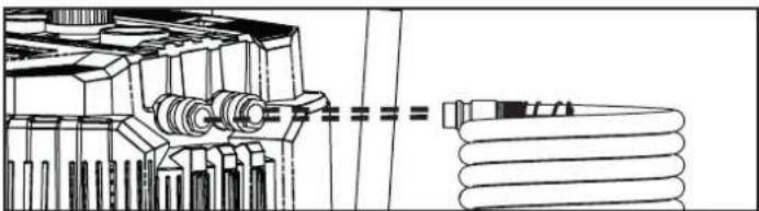
natural_image
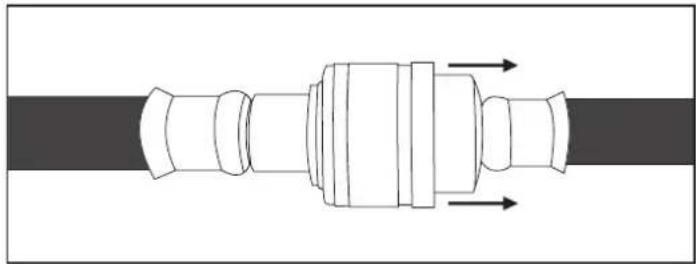
Technical line drawing of a mechanical assembly with gears and shafts (no text or symbols)Pay attention to the maximum working pressure of the hose. Operate the hose 17 only within the specified parameters (see technical data).
Press the pneumatic hose ⑦ into one of the two quick couplings ②. The pneumatic hose ⑰ locks into place.
Connect the pneumatic tool via the quick coupling of the pneumatic hose 17.
■ After work, remove the tool from the pneumatic hose 17, by pulling the quick coupling firmly backwards. Hold the pneumatic hose 17 firmly so that the hose swinging around cannot injure anyone.
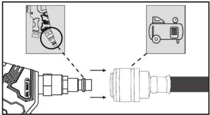
natural_image
Pure mechanical component diagram without any text, numbers, or symbols5. Operating the pneumatic tyre inflation gauge
5.1 Before first use
The product may only be operated with cleaned, condensate-free and oil-free compressed air. The maximum working pressure of 8 bar on the product must not be exceeded.
Connect the product to the compressor by connecting the quick coupling of the pneumatic hose 17 to the connector plug 20. The lock is automatic. You regulate the air pressure with the integrated pressure regulator 10.
5.2 First use
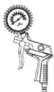
The pneumatic tyre inflation gauge makes inflation easy. The pressure gauge 18 is used to check the pressure. With the integrated drain valve 19 it is possible to lower pressure that is too high.
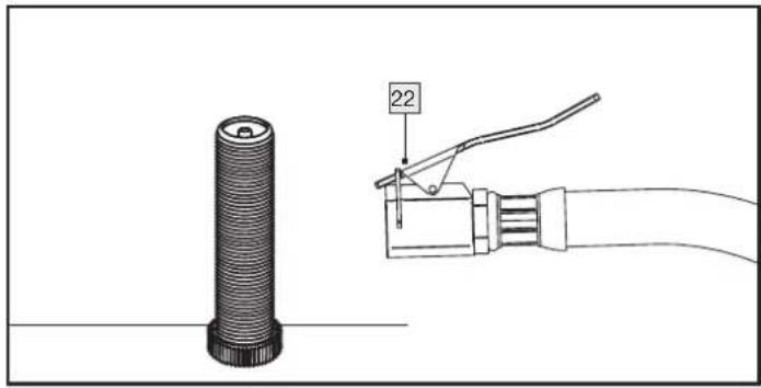
5.2.1 Without adapter
Press the quick-release level2 down to put it on.
Place the quick-release lever on the valve and then release it.
Press the trigger.
Read the built-up air pressure on the pressure gauge.
■ Release the trigger.
■ Push the quick-release lever down and pull it off the valve.
natural_image
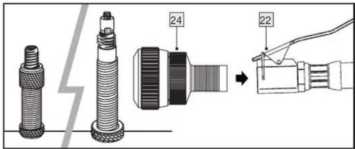
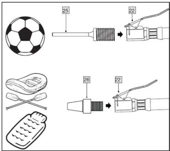
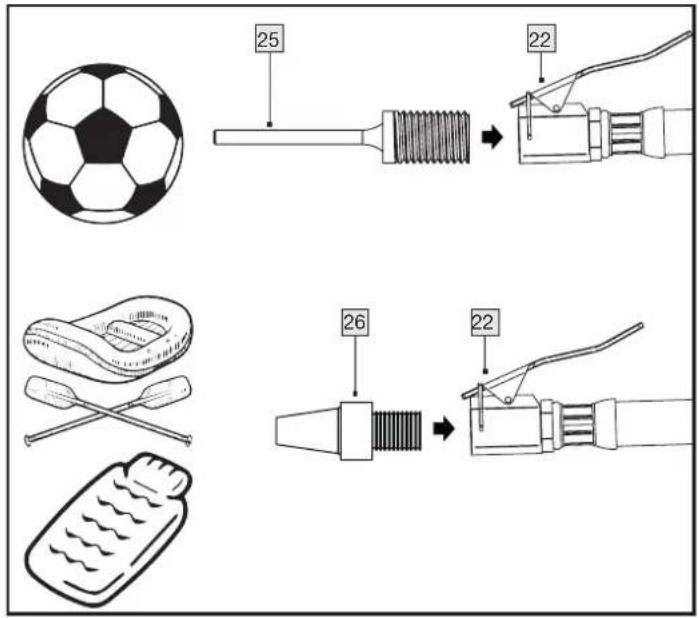
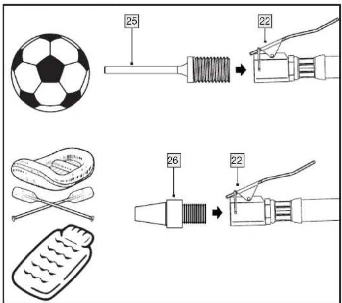
Technical illustration of a mechanical component with a cylindrical shaft and a lever handle (no text or symbols)5.2.2 With valve adapter, ball needle, universal adapter
Press the quick-release level2 down to put it on.
- Insert the valve adapter into the quick-release lever 22 and then release it.
Now press the valve adapter onto the valve.
Press the trigger.
Read the built-up air pressure on the pressure gauge.
■ Release the trigger.
■ Push the quick-release lever down and pull it off the valve.
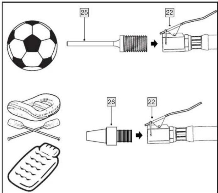
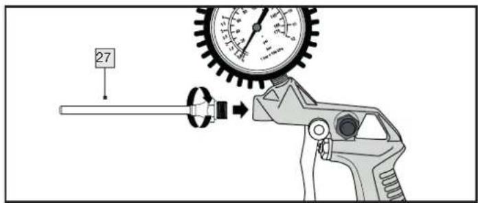
5.2.3 With extension nozzle
The extension nozzle 27 is for cleaning/blowing cavities or hard-to-reach places, as well as for cleaning dirty implements. The continuously adjustable trigger 21 allows the compressed air to be metered.
Screw the extension nozzle 27 directly into the pneumatic tyre inflation gauge. You do not need the hose with quick-release lever 23 for this application.
6. Cleaning, maintenance, transport and storage by the user
Clean and maintain your compressor carefully and regularly. This is the only way to ensure flawless operation and a long service life.
Regardless of the number of operations or actuations, maintain and clean the device after each use.
6.1 Safety measures
Be sure to observe the following instructions during maintenance and cleaning work:
- Switch off the compressor by pressing the on-off switch 8 to the "0" position.
- Disconnect the compressor from the power supply by pulling the mains plug. Thus, the compressor is separated from the energy supply.
- Relieve the pressure from the compressor to avoid material damage. For example, you can connect an air blow gun to the compressor and use it to empty the pressure vessel 3.
- Attention should be paid to the disposal instructions given in this manual. Improper disposal may harm the environment or your health.
Clean the device of hazardous substances deposited on it (due to work processes) before servicing. Avoid any skin contact with these substances. If skin comes into contact with hazardous dusts, this can lead to severe dermatitis. If dust is generated or stirred up during maintenance work, it can be inhaled.
Always wear protective gloves and a protective mask!
The device must only be operated and maintained by trained persons. Repairs may only be carried out by qualified persons.
If possible, inspections, adjustments and maintenance work should be carried out by the same person or their deputy and documented in a maintenance log.
6.2 Maintenance of the pressure vessel
- Drain condensation after each operation, but at least once a week. Condensation may only be drained when the tank 3 is NOT under pressure.
Open and close the safety valve at least three times a year. The safety valve 7 protects the compressor. It protects the pressurised container 3. As soon as the air in the container 3 reaches or exceeds the maximum permissible operating pressure, the safety valve 7 opens and allows the compressed air to escape, thereby reducing the pressure in the compressor.
6.3 Cleaning
■ Clean the device only when it is switched off and cold.
Clean the housing of the device only with a slightly damp, soft cloth. Never use harsh and/or abrasive cleaning agents.
■ Make sure that no moisture enters the device during cleaning to avoid irreparable damage to the device.
- You can also remove dust deposits using an air blow gun (at low pressure).
6.4 Transport
By tilting the transport handle the compressor can be transported on the wheels 4.
6.5 Storage
To protect against contamination, the compressor should be covered after each use. The packaging can be used to store the compressor.
Do not cover the compressor until it has cooled down completely. Keep the compressor and its manual together. Store the machine and its accessories in a dark, dry, dust-free and frost-free place.
6.6 Troubleshooting
| Malfunction Possible cause(s) Remedy | ||
| Engine does not start. No or too low voltage. | Make sure that the mains plug is inserted | in the socket. Check the fuse and replace it if necessary. Check the mains voltage. |
| Outdoor temperature too low. Ensure +5 °C | ambient temperature. | |
| Device is not switched on. | Press the on/off switch 8 to position “I”, to switch on the compressor. | |
| Extension cable is too long or too thin. Replace the extension cable (min. 1.5 mm2, max. 5 m long). | ||
| Unusual noises Pneumatic connectors are loose. | Check all connecting parts and tighten | them carefully if necessary. |
| Strong vibrations | Pneumatic connectors are loose. | Servicing and maintaining the compressor. |
| Compressor switches on frequently. | Compressor is overloaded. | Observe the manufacturer's instructions for your tool or equipment, especially with regard to the amount of compressed air required. |
| Too much condensation in the tank 3. | Empty the tank 3 regularly. | |
| Compressor runs without interruption / compressor does not reach cut-off pressure. | Air consumption for connected pneumatic tools and devices is too high. | Comply with the manufacturer's instructions for your pneumatic tool, especially with regard to the amount of compressed air required. |
| Quick couplings 2 leaking. | Check quick coupling 2 replace if necessary. | |
| Pneumatic connectors leaking. | Check pneumatic hose and tools, replace if necessary. | |
7. Disposal
- The device, accessories and packaging* should be recycled in an environmentally friendly manner.
The crossed-out dustbin indicates that the device must be collected separately from unsorted municipal waste at the end of its service life.

This product is subject to the European Directive 2012/19/EU. Do not dispose of the product in household waste, but via municipal collection points for material recycling! Further information on how to dispose of the discarded device can be obtained from your local authority or city council.

The packaging is made of environmentally friendly materials that you can dispose of at your local recycling centres.


The Triman logo is valid in France only.

Observe the labelling of the packaging materials when separating waste; these are marked with abbreviations (a) and numbers (b) with the following meaning: 1–7: Plastics/20–22: Paper and cardboard/80-98: Composites.
7.1 Environmental compatibility and material disposal
Lubricating oil must not get into the soil, water or waste water. Lubricating oil is special waste that must be disposed of accordingly. Observe the local regulations. Dispose of lubricating oil and packaging containing residues at your local collection point, petrol station or oil dealer.
* Non-contaminated or cleaned packaging can be recycled.
The compressor operates without oil, so there are no special instructions to follow when disposing of condensation.
8. ROWI Germany GmbH Warranty
Dear Customer,
This appliance has a 3-year warranty valid from the date of purchase. If this product has any faults, you, the buyer, have certain statutory rights. Your statutory rights are not restricted in any way by the warranty described below.
Warranty conditions
The validity period of the warranty starts from the date of purchase. Please keep your original receipt in a safe place. This document will be required as proof of purchase.
If any material or production fault occurs within three years of the date of purchase of the product, we will either repair or replace the product for you or refund the purchase price at our discretion. This warranty service is dependent on you presenting the defective appliance and the proof of purchase (receipt) and a short written description of the fault and its time of occurrence.
If the defect is covered by the warranty, your product will either be repaired or replaced by us. The repair or replacement of a product does not signify the beginning of a new warranty period.
Warranty period and statutory claims for defects
The warranty period is not prolonged by repairs effected under the warranty. This also applies to replaced and repaired components. Any damage and defects present at the time of purchase must be reported immediately after unpacking. Repairs carried out after expiry of the warranty period shall be subject to a fee.
Scope of the warranty
This appliance has been manufactured in accordance with strict quality guidelines and inspected meticulously prior to delivery.
The warranty covers material faults or production faults. The warranty does not extend to product parts subject to normal wear and tear or fragile parts such as switches, batteries or those made of glass.
The warranty does not apply if the product has been damaged, improperly used or improperly maintained. The directions in the operating instructions for the product regarding proper use of the product are to be strictly followed. Uses and actions that are discouraged in the operating instructions or which are warned against must be avoided.
This product is intended solely for private use and not for commercial purposes. The warranty shall be deemed void in cases of misuse or improper handling, use of force and modifications/repairs which have not been carried out by one of our authorised Service centres.
Warranty claim procedure
To ensure quick processing of your case, please observe the following instructions:
- For all enquiries, please have the receipt and item number (IAN 465621_2404) ready as proof of purchase.
Please refer to the type plate on the product, an engraving on the product, the title page of your instructions (bottom left) or the sticker on the back or underside of the product for the article number. - Should functional faults or other defects occur, please first contact the service department named below by telephone or e-mail.
- You can then send a product recorded as defective to the service address provided to you free of charge, enclosing the proof of purchase (receipt) and stating what the defect is and when it occurred.

You can view and download these and many other manuals at parkside-diy.com. This QR code will take you directly to parkside-diy.com. Select your country and search for the manuals using the search mask. Entering the article number (IAN) 465621_2404 will take you to the operating instructions for your article.
9. Service
If you encounter problems while operating your ROWI Germany product, please proceed as follows:
Making contact
You can reach the ROWI Germany Service Team at:
ROWI Germany GmbH
(free of charge from landlines)
IAN 465621_2404
Most problems can already be solved during the competent, technical consultation of our service team.
10. Translation of the original declaration of conformity
We, ROWI Germany GmbH, Werner-von-Siemens-Str. 27, 76694 Forst, Germany, hereby declare that this product complies with the following standards, normative documents and EU directives:
Machinery Directive: 2006/42/EC
Electromagnetic compatibility: 2014/30/EU
Outdoor Directive: 2000/14/EC + 2005/88/EC
Notified body: No. 0036 // TÜV SÜD Industrie Service GmbH, Westendstraße 199, 80686 Munich, Germany Conformity assessment procedure according to Annex VI. Sound power level L_WA : Measured: 94 dB(A) – Guaranteed: 96 dB(A)
Pressure Vessel Directive: 2014/29/EU
RoHS Directive: 2011/65/EU* incl. the Delegated Directive (EU) 2015/863
Applied harmonised standards:
EN 1012-1:2010
EN 62841-1:2015
EN IEC 61000-6-1:2019
EN IEC 61000-6-3:2021
Device name: Vertical Compressor
Model number: PVKO 50 C3
Manufacture: 10/2024
Lot number: IAN 465621_2404
Machinery Directive: 2006/42/EC
Applied harmonised standards: EN 1953:2013
Device name: Pneumatic tyre inflation gauge
Model number: TG-1
Manufacture: 10/2024
Lot number: IAN 465621_2404
Documentation officer: Marc Stockenberger
Place: Forst
Date/manufacturer signature: 06/08/2024

Marc Stockenberger
Managing Director
We reserve the right to make technical changes in the interest of further development.
The sole responsibility for issuing this declaration of conformity lies with the manufacturer.
* The subject of the declaration described above complies with the provisions of Directive 2011/65/EU of the European Parliament and of the Council of 8 June 2011 on the restriction of the use of certain hazardous substances in electrical and electronic equipment.
natural_image
Technical line drawing of a mechanical component with three circular gauges and a top panel (no text or symbols)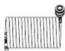
natural_image
Line drawing of a pressure gauge measuring a hose with a tool (no text or symbols)Innendurchmesser: ∅ 5,0 mm
Wandstärke: 1,5 mm
natural_image
Technical line drawing of a mechanical component with rotational arrows indicating motion (no text or symbols)natural_image
Diagram showing a mechanical component with arrows indicating motion, no text or symbols presentHINWEIS
natural_image
Technical line drawing of a mechanical assembly with gears and shafts (no text or symbols)natural_image
Pure mechanical component diagram without any text, numbers, or symbolsnatural_image
Technical illustration of a cylindrical component and a wire clamp tool (no text or symbols)5.2.2 Mit Ventiladapter, Ballnadel, Universaladapter

EN IEC 61000-6-3:2021
natural_image
Top-down schematic of a vehicle or industrial control panel with three circular gauges (no text or labels visible)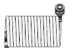
natural_image
Line drawing of a pressure gauge tool with tubing and valve (no text or symbols)natural_image
Technical line drawing of a mechanical component with rotational arrows indicating motion (no text or symbols)REMARQUE
natural_image
Technical line drawing of a mechanical assembly with gears and shafts (no text or symbols)natural_image
Pure mechanical component diagram without any text, numbers, or symbolsnatural_image
Technical illustration of a mechanical component with a cylindrical shaft and a clamping tool (no text or symbols)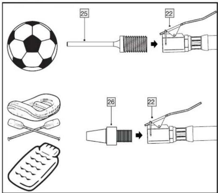
PDF ONLINE parkside-diy.com
EN IEC 61000-6-3:2021
natural_image
Top-down schematic of a vehicle or industrial control panel with three circular gauges (no text or labels visible)

natural_image
Line drawing of a spray gun with a gauge and hose (no text or symbols)natural_image
Technical line drawing of a mechanical component with rotational arrows indicating motion (no text or symbols)AANWIJZING
natural_image
Technical line drawing of a mechanical assembly with gears and springs (no text or symbols)natural_image
Pure mechanical component diagram without any text, numbers, or symbols5. Bediening van de perslucht-bandenspanningsmeter
natural_image
Technical illustration of a cylindrical component and a wire clamp tool (no text or symbols)5.2.2 Met klepadapter, balnaald, universele adapter
EN IEC 61000-6-3:2021
natural_image
Technical line drawing of a mechanical or electrical component with three circular gauges (no text or symbols)
natural_image
Line drawing of a pressure gauge tool with attached tubing (no text or symbols)1.4 Technické údaje
1.4.1 Kompresor
natural_image
Technical line drawing of a mechanical component with rotational arrows indicating motion (no text or symbols)natural_image
Diagram of a car tire assembly with a numbered component and directional arrows indicating motion (no text or symbols)UPOZORNĚNÍ
natural_image
Technical line drawing of a mechanical assembly with gears and shafts (no text or symbols)natural_image
Pure mechanical component diagram without any text, numbers, or symbolsnatural_image
Technical illustration of a mechanical component with a threaded shaft and a clamping tool (no text or symbols)
5.2.3 S prodlužovací tryskou
EN IEC 61000-6-3:2021
natural_image
Technical line drawing of a mechanical component with three circular gauges (no text or symbols)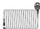

natural_image
Line drawing of a pressure gauge measuring a hose with a probe (no text or symbols)1.4 Dane techniczne
1.4.1 Sprężarka
natural_image
Technical line drawing of a mechanical component with rotational arrows indicating motion (no text or symbols)UWAGA
natural_image
Technical line drawing of a mechanical assembly with gears and springs (no text or symbols)natural_image
Pure mechanical component diagram without any text, numbers, or symbolsnatural_image
Technical diagram showing a cylindrical component and a tool with a labeled part (22), no readable text or symbols present.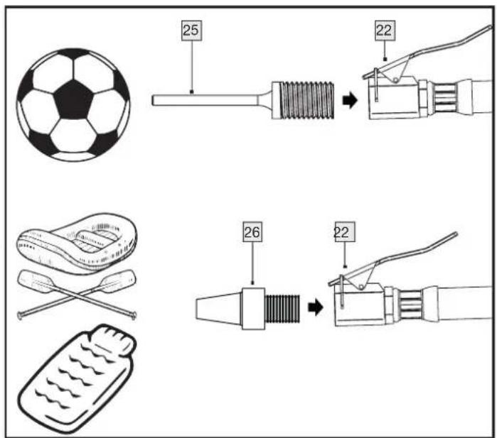
EN IEC 61000-6-3:2021
natural_image
Top-down schematic of a mechanical or electrical component with three circular gauges (no text or symbols)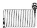

natural_image
Line drawing of a pressure gauge tool with attached tubing (no text or symbols)1.4 Technické údaje
1.4.1 Kompresor
Menovité napätie: 230 V\~ 50 Hz
Vložte skrutku kolesa 15 do podložky 14 a potom cez otvor v kolese 4.
Naskrutkujte maticu 13 na skrutku kolesa 15. Uistite sa, že kolesom 4 možno na skrutke ešte otáčat.
■Skrutku kolesa 15 zasuňtecez otvor na závese kolesa.
■Koleso 4 zaistite prírubovou maticou 12.
natural_image
Technical line drawing of a mechanical component with rotational arrows indicating motion (no text or symbols)natural_image
Technical line drawing of a mechanical assembly with gears and shafts (no text or symbols)natural_image
Pure mechanical component diagram without any text, numbers, or symbolsnatural_image
Technical illustration of a cylindrical component and a cable with a labeled pin (no text or symbols present)5.2.2 S adaptérom na ventil, gulovou ihlou, univerzálnym adaptérom
5.2.3 S predlžovacou dýzou
EN IEC 61000-6-3:2021
natural_image
Technical line drawing of a mechanical component with three gauges and a top panel (no text or symbols)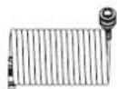
natural_image
Line drawing of a pressure gauge tool with tubing and needle, no text or symbols present1.4 Datos técnicos
1.4.1 Compresor
natural_image
Technical line drawing of a mechanical component with rotational arrows indicating motion (no text or symbols)ADVERTENCIA
natural_image
Technical line drawing of a mechanical assembly with gears and shafts (no text or symbols)natural_image
Pure mechanical component diagram without any text, numbers, or symbolsnatural_image
Technical illustration of a mechanical component with a cylindrical shaft and a cable being inserted (no text or symbols)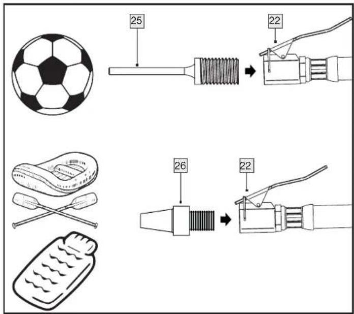
EN IEC 61000-6-3:2021
natural_image
Top-down schematic of a mechanical or electrical component with three circular gauges (no text or symbols)
natural_image
Line drawing of a pressure tool with a gauge and tubing (no text or symbols)1.4 Tekniske data
1.4.1 Kompressor
natural_image
Technical line drawing of a mechanical component with rotational arrows indicating motion (no text or symbols)natural_image
Diagram of a car wheel assembly with a numbered component and directional arrows (no text or symbols)BEMÆRK
natural_image
Technical line drawing of a mechanical assembly with gears and shafts (no text or symbols)natural_image
Pure mechanical component diagram without any text, numbers, or symbolsnatural_image
Technical illustration of a mechanical component with a cylindrical shaft and a clamping tool (no text or symbols)5.2.2 Med ventiladapter, ventilnål, universaladapter
EN IEC 61000-6-3:2021
Ansvarlig for dokumentation: Marc Stockenberger
Sted: Forst
Dato/producentens underskrift: 06.08.2024

Marc Stockenberger
Direktør
natural_image
Top-down schematic of a vehicle dashboard with three circular gauges (no text or labels)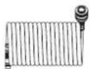

natural_image
Line drawing of a spray gun with a gauge and hose (no text or symbols)1.4 Dati tecnici
1.4.1 Compressore
natural_image
Technical line drawing of a mechanical component with rotational arrows indicating motion (no text or symbols)natural_image
Technical line drawing of a mechanical assembly with gears and springs (no text or symbols)natural_image
Pure mechanical component diagram without any text, numbers, or symbolsnatural_image
Technical diagram showing a cylindrical component and a wire being inserted into a cable (no text or symbols present)
EN IEC 61000-6-3:2021
natural_image
Technical line drawing of a mechanical component with three circular gauges (no text or symbols)

natural_image
Line drawing of a pressure regulator with gauge and hose (no text or symbols)1.4 Műszaki adatok
1.4.1 Kompresszor
natural_image
Technical line drawing of a mechanical component with rotational arrows indicating motion (no text or symbols)natural_image
Technical line drawing of a mechanical assembly with gears and springs (no text or symbols)natural_image
Pure mechanical component diagram without any text, numbers, or symbolsnatural_image
Technical diagram showing a cylindrical component and a wire-wrapped electrical plug with a labeled connection point (no text or symbols present)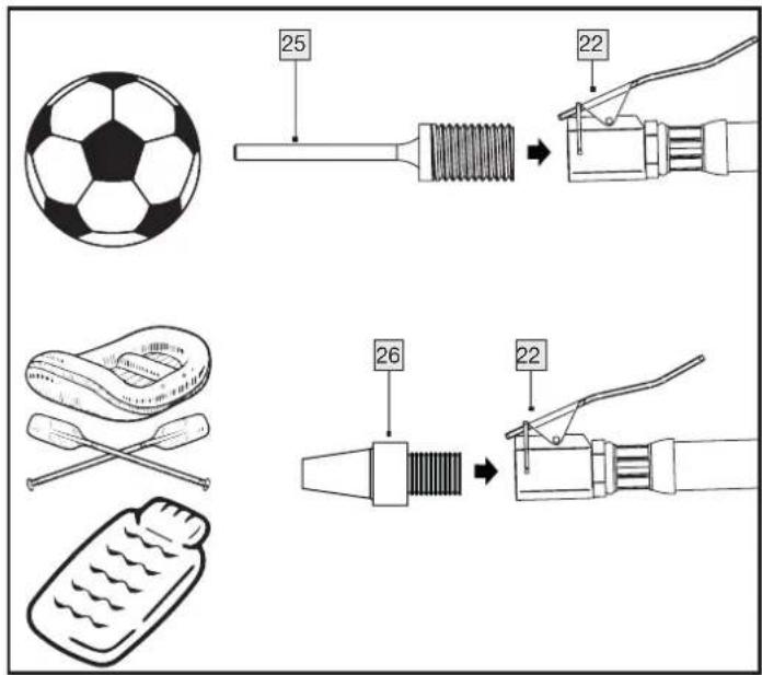
EN IEC 61000-6-3:2021