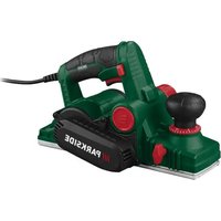
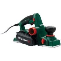
PEH 30 E5 - Electric planer PARKSIDE - Free user manual and instructions
Find the device manual for free PEH 30 E5 PARKSIDE in PDF.


| Product type | Electric planer |
| Brand | Parkside |
| Model | PEH 30 E5 |
| Rated voltage | 230 V~, 50 Hz |
| Rated power | 750 W |
| No-load speed | 16500 min⁻¹ |
| Depth of cut | 0 – 3 mm |
| Max. rabbet depth | ≤ 18 mm |
| Max. planing width | ≤ 82 mm |
| Power cable length | 3 m |
| Weight | ≈ 2.9 kg |
| Sound pressure level (LpA) | 89.8 dB(A); K=3 dB |
| Sound power level (LWA) | 97.8 dB(A); K=3 dB |
| Vibration (handle) | 2.568 m/s²; K=1.5 m/s² |
| Vibration (auxiliary handle) | 3.771 m/s²; K=1.5 m/s² |
| Protection class | II (double insulation) |
| Items supplied | Electric planer, parallel stop, paper bag, hex key, combination wrench, countersunk screw, washer, wing nut, holder, rabbet depth stop, adapter for extraction system |
| Main functions | Planing, chamfering, rabbet cutting |
| Safety features | Switch lock, retractable blade guard, double insulation |
| Maintenance | Regular cleaning, drive belt replacement, rotating/replacing planer blades |
| Warranty | 3 years |
Frequently Asked Questions - PEH 30 E5 PARKSIDE
User questions about PEH 30 E5 PARKSIDE
0 question about this device. Answer the ones you know or ask your own.
Ask a new question about this device
Download the instructions for your Electric planer in PDF format for free! Find your manual PEH 30 E5 - PARKSIDE and take your electronic device back in hand. On this page are published all the documents necessary for the use of your device. PEH 30 E5 by PARKSIDE.
USER MANUAL PEH 30 E5 PARKSIDE
natural_image
Black Parkside electric plow with visible circuit breaker and control panel (no text or symbols on device body)Translation of the original instructions
NL BE
Elektrische schaafmachine
Before reading, unfold the page containing the illustrations and familiarise yourself with all functions of the device.
FR BE
Service-Center....15
Importeur.... 15
27 2× Hobelmesser 91106283
Scope of delivery/accessories......17
Overview.... 18
Description of functions....18
Technical data....18
Safety information....19
Meaning of the safety information...... 19
Pictograms and symbols.... 19
General Power Tool Safety
Warnings....19
Safety instructions for planers.... 21
Additional safety instructions......21
Residual risks....21
Preparation....22
Control elements....22
Removing and fitting the chip ejector.... 22
Using the parallel guide.... 22
Using a rebate depth stop.... 22
Connecting dust extraction....22
Rotating or replacing the planer blades.... 23
Operation.... 23
Working instructions.... 23
Switching on and off....24
Transport....24
Cleaning, maintenance and storage..... 24
Cleaning....24
Maintenance.... 24
Replacing the drive belt.... 25
Storage.... 25
Disposal/environmental protection......25
Service.... 25
Guarantee.... 25
Repair service.... 26
Service Centre.... 26
Importer.... 27
Spare parts and accessories.... 27
Translation of the original EU declaration of conformity.... 27
Exploded view.... 143
Introduction
Congratulations on purchasing your new electric planer (hereafter referred to as device or power tool).
You have chosen a high-quality device. This device was quality-tested and subjected to a final inspection during production, therefore ensuring proper functioning of your device.

The instruction manual forms part of this device. It contains important information on safety, use and disposal. Read the instruction manual carefully. Familiarise yourself with the controls and how to use the device correctly. Use the device only as described and for the stated fields of application. Store the instruction manual carefully and ensure that all documents are handed over in the event that the device is passed on to another user.
Proper use
This machine is only intended for the following use:
- Planing, chamfering and rebating wood materials, such as beams and boards. Workpieces may only be processed if they are secured appropriately.
Any other use that is not expressly permitted in this instruction manual may pose a serious hazard to the user and result in damage to the device. The operator or user of the machine is responsible for any accidents or personal injury and/or material damage to third parties or their property. The machine is intended to be used by do-it-yourselfers. It was not designed for heavy commercial use. The warranty is void in the case of commercial use. The manufacturer is not liable for damage caused by improper use or incorrect operation.
Scope of delivery/accessories
Unpack the device and check that everything is present.
Dispose of the packaging material properly.
- Electric Planer
- Parallel guide
- Paper bag
- Hex key
- Open-end wrench
- Carriage bolt
- Washer
- Wing nut
- Holder
-
Depth stop
-
Adapter for external dust extraction
• Translation of the original instructions
Overview

The illustrations for the device can be found on the front and back fold-out page.
1 Scale (Cutting depth)
2 Cutting depth adjustment / Auxiliary handle (Insulated gripping surface)
3 Switch lock
4 On/Off switch
5 Handle (Insulated gripping surface)
6 Power cord
7 Planer sole
8 Cover
9 Screw (Cover)
10 Shavings ejector
11 Wing screw
12 Holder (Parallel guide)
13 V-groove
14 Adapter for external dust extraction
15 Holder (Depth stop)
16 Retractable planer blade guard
17 Parking shoe
18 Hex key
19 Open-end wrench
20 Carriage bolt
21 Washer
22 Wing nut
23 Parallel guide
24 Holder (Parallel guide)
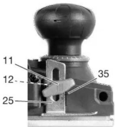
25 Depth stop
Fig. A
26 Blade holder
27 Planer blades
28 Clamping plate
29 Blade shaft
30 Hexagon socket screw
31 Hexagon bolt
Fig. B
32 Belt wheel (large)
33 Driving belt
34 Belt wheel (small)
Fig. C
35 Reading mark (Depth stop)
Description of functions
The tool has a rotating planer shaft equipped with two planer blades. The tool is suitable for planing beams and boards, bevelling edges and creating rebates.
Please refer to the descriptions below for information on how the operating elements work.
Technical data
Electric Planer ...... PEH 30 E5
Rated voltage U 230 V\~, 50 Hz
Rated input power P 750 W
Protection class ...... □ II (double insulation)
No-load rotation speed n_0 .....16500 min ^-1
Cutting depth 0 - 3 mm
Rebate depth ....≤18 mm
Planer width ....≤82 mm
Length Power cord 3 m
Weight ≈ 2.9 kg
Sound pressure level ( L_pA )
89.8 dB; K_pA=3 dB
Sound power level ( L_WA ) 97.8 dB; K_WA=3 dB Vibration ( a_h )
- Handle ......2.568 m/s ^2 ; K=1.5 m/s ^2
– Auxiliary handle .....3.771m/s ^2 ; K=1.5 m/s ^2
⚠️ CAUTION! Hearing damage! Wear ear protection.
Levels of noise and vibration were determined according to the standards and regulations in the declaration of conformity.
The specified total vibration value and the stated noise emission value have been measured according to a standardised test method and can be used to compare one power tool with another. The specified total vibration value and the stated specified noise emission value can also be used for a provisional assessment of the load.
⚠ WARNING! The vibration and noise emissions may deviate from the specified values during actual use of the power tool, depending on how the power tool is being used. Try to keep the exposure to vibrations as low as possible. An example of a measure to reduce vibration exposure is limiting the working hours. All parts of the operating cycle have to be considered while doing so (for example, times when the power tool is switched off and times when it is switched on but running without any load).
Safety information
This section deals with the basic safety instructions for using the device.
Meaning of the safety information
DANGER! If you do not observe this safety instruction, an accident will occur. The result of which is severe bodily injury or death.
⚠ WARNING! If you do not observe this safety instruction, an accident may occur. The result of which is likely severe bodily injury or death.
CAUTION! If you do not observe this safety instruction, an accident will occur. The result of which is likely minor or moderate bodily injury.
NOTICE! If you do not observe this safety instruction, an accident will occur. The result of which is possible damage to property.
Pictograms and symbols
Symbols on the device

Read the instruction manual

Use respiratory protection

Protection class II (double insulation)

Cutting depth adjustment

Direction of travel of the planer blade

Lock direction of rotation
Waste electrical and electronic equipment (WEEE) must not be disposed of with domestic waste.
General Power Tool Safety Warnings
WARNING! Read all safety warnings, instructions, illustrations and specifications provided with this power tool. Failure to follow all instructions listed below may result in electric shock, fire and/or serious injury. Save all warnings and instructions for future reference.
The term “power tool” in the warnings refers to your mains-operated (corded) power tool or battery-operated (cordless) power tool.
1. WORK AREA SAFETY
a) Keep work area clean and well lit.
Cluttered or dark areas invite accidents.
b) Do not operate power tools in explosive atmospheres, such as in the presence of flammable liquids, gases or dust. Power tools create sparks which may ignite the dust or fumes.
c) Keep children and bystanders away while operating a power tool. Distractions can cause you to lose control.
2. ELECTRICAL SAFETY
a) Power tool plugs must match the outlet. Never modify the plug in any way. Do not use any adapter plugs with earthed (grounded) power tools. Un-modified plugs and matching outlets will reduce risk of electric shock.
b) Avoid body contact with earthed or grounded surfaces, such as pipes, radiators, ranges and refrigerators. There is an increased risk of electric shock if your body is earthed or grounded.
c) Do not expose power tools to rain or wet conditions. Water entering a power tool will increase the risk of electric shock.
d) Do not abuse the cord. Never use the cord for carrying, pulling or unplugging the power tool. Keep cord away from heat, oil, sharp edges or moving parts. Damaged or entangled cords increase the risk of electric shock.
e) When operating a power tool outdoors, use an extension cord suitable for outdoor use. Use of a cord suitable for outdoor use reduces the risk of electric shock.
f) If operating a power tool in a damp location is unavoidable, use a residual current device (RCD) protected supply. Use of an RCD reduces the risk of electric shock.
3. PERSONAL SAFETY
a) Stay alert, watch what you are doing and use common sense when operating a power tool. Do not use a power tool while you are tired or under the influence of drugs, alcohol or medication. A moment of inattention while operating power tools may result in serious personal injury.
b) Use personal protective equipment. Always wear eye protection. Protective equipment such as a dust mask, non-skid safety shoes, hard hat or hearing protection used for appropriate conditions will reduce personal injuries.
c) Prevent unintentional starting. Ensure the switch is in the off-position before connecting to power source and/or battery pack, picking up or carrying the tool. Carrying power tools with your finger on the switch or energising power tools that have the switch on invites accidents.
d) Remove any adjusting key or wrench before turning the power tool on. A wrench or a key left attached to a rotating part of the power tool may result in personal injury.
e) Do not overreach. Keep proper footing and balance at all times. This enables better control of the power tool in unexpected situations.
f) Dress properly. Do not wear loose clothing or jewellery. Keep your hair and clothing away from moving parts. Loose clothes, jewellery or long hair can be caught in moving parts.
g) If devices are provided for the connection of dust extraction and collection facilities, ensure these are connected and properly used. Use of dust collection can reduce dust-related hazards.
h) Do not let familiarity gained from frequent use of tools allow you to be-
come complacent and ignore tool safety principles. A careless action can cause severe injury within a fraction of a second.
4. POWER TOOL USE AND CARE
a) Do not force the power tool. Use the correct power tool for your application. The correct power tool will do the job better and safer at the rate for which it was designed.
b) Do not use the power tool if the switch does not turn it on and off. Any power tool that cannot be controlled with the switch is dangerous and must be repaired.
c) Disconnect the plug from the power source and/or remove the battery pack, if detachable, from the power tool before making any adjustments, changing accessories, or storing power tools. Such preventive safety measures reduce the risk of starting the power tool accidentally.
d) Store idle power tools out of the reach of children and do not allow persons unfamiliar with the power tool or these instructions to operate the power tool. Power tools are dangerous in the hands of untrained users.
e) Maintain power tools and accessories. Check for misalignment or binding of moving parts, breakage of parts and any other condition that may affect the power tool's operation. If damaged, have the power tool repaired before use. Many accidents are caused by poorly maintained power tools.
f) Keep cutting tools sharp and clean. Properly maintained cutting tools with sharp cutting edges are less likely to bind and are easier to control.
g) Use the power tool, accessories and tool bits etc. in accordance with these instructions, taking into account the working conditions and the work to be performed. Use of the power tool for operations different from those intended could result in a hazardous situation.
h) Keep handles and grasping surfaces dry, clean and free from oil and grease. Slippery handles and grasping surfaces do not allow for safe handling and control of the tool in unexpected situations.
5. SERVICE
a) Have your power tool serviced by a qualified repair person using only identical replacement parts. This will ensure that the safety of the power tool is maintained.
Safety instructions for planers
- Wait for the cutter to stop before setting the tool down. An exposed rotating cutter may engage the surface leading to possible loss of control and serious injury.
- Hold the power tool by insulated gripping surfaces, because the cutter may contact its own cord. Cutting a “live” wire may make exposed metal parts of the power tool “live” and could give the operator an electric shock.
- Use clamps or another practical way to secure and support the workpiece to a stable platform. Holding the workpiece by your hand or against the body leaves it unstable and may lead to loss of control.
Additional safety instructions
- Only connect the device to a power outlet with a residual current device (RCD) with a rated residual current no more than 30 mA.
- If the power cord of this device is damaged, it must be replaced by the manufacturer or their representative to avoid safety hazards. contact the service centre.
- Always hold the power tool so that it lays flat on the workpiece when working. The power tool could otherwise tilt and cause injury.
- Move the power tool against the workpiece only when it is switched on. Otherwise, there is a risk of kickback if the attachment tool jams in the workpiece.
- Do not reach into the chip ejector with your hands. You may injure yourself on rotating parts.
- Never plane over metal objects, nails or screws. The blades and blade shaft may be damaged and lead to increased vibrations.
- Do not work on materials containing asbestos. Asbestos is considered carcinogenic.
- Harmful dust can occur when working. Wear a respiratory mask and attach an external dust extraction system.
- Check the planer blade regularly for damage. Only use sharp, undamaged planer blades.
- Keep the ventilation openings clean.
- Switch off the device and disconnect the plug from the power outlet. Make sure that all moving parts have come to a complete stop:
- when leaving the device
- wenn die Netzanschlussleitung beschädigt oder verheddert ist
- before removing obstructions or loosening blockages
- before checking the device, cleaning it or performing maintenance work on it
• after touching a foreign body in order to check the machine for damage, - for an immediate check if the machine begins to vibrate excessively.
- For safety reasons, replace worn or damaged parts. Only use original spare parts and accessories.
- Only use accessories recommended by PARKSIDE. Unsuitable accessories may cause electric shock or fire.
Residual risks
There will always be residual risks even if you operate this device according to the instructions. The following hazards may occur in connection with the type and design of this device:
- Eye damage if no suitable eye protection is worn.
- Lung damage if suitable respiratory protection is not worn.
- Hearing damage if suitable ear protection is not worn.
- Health injuries resulting from the effect of hand/arm vibration in the event that the tool is used over a longer period of time or is not used and maintained properly.
- Cutting injuries
⚠ WARNING! Danger due to electromagnetic field generated while the tool is in operation. Under certain circumstances, this field may negatively affect active or passive medical implants. In order to reduce the danger of serious or fatal injuries, we recommend that individuals who wear medical implants
should consult their doctor and the manufacturer of the implant before operating the tool.
Preparation
⚠ WARNING! Risk of injury due to unintentional start-up. Do not insert the plug into the outlet until the device is fully prepared for use.
Control elements
Familiarise yourself with the operating elements before using the device for the first time.
• Cutting depth adjustment (2)
- Set the cutting depth using the rotary knob.
- Adjustable cutting depth: 0 – 3 mm
- Switch lock (3)
- Locks the on/off switch against unintentional operation.
- Unlocking: Press
- On/Off switch (4)
- Switching on: Press
- Control the speed progressively: The further you press the on/off switch, the higher the speed.
- Switching off: Release
- Parking shoe (17)
- The parking shoe allows the planer to be set down without damaging the surface.
- The parking shoe extends when you lift the planer sole off the workpiece.
- When planing, the park shoe is automatically lowered into the planing sole.
Removing and fitting the chip ejector
Notes
- Do not work without the chip ejector.
- You can fit the chip ejector on either side.
- If possible, connect an external dust extraction system.
Removing the chip ejector
-
Unlock the chip ejector (10): Turn the chip ejector against direction LOCK.
-
Pull the chip ejector (10) out of the tool.
Fitting the chip ejector
- Push the chip ejector (10) into the tool.
Make sure that the lug on the chip ejector fits into the recess on the tool.
- Lock the chip ejector (10): Turn the chip ejector in direction LOCK.
Using the parallel guide
Notes
- The parallel guide makes it easier to create rebates.
- Apply pressure sideways.
Fitting the parallel guide (Fig. C)
- Insert the carriage bolt (20) through the holder (24) and parallel guide (23).
- Put the washer (21) on the carriage bolt (20).
- Tighten the wing nut (22) on the carriage bolt (20).
- Fit the holder (24) on the tool using the wing screw (11).
Adjusting the parallel guide (Fig. C)
- Undo the wing nut (22).
- Set the desired width.
- Tighten the wing nut (22) again.
Using a rebate depth stop
Notes
- The rebate depth stop makes it easier to create rebates.
Procedure (Fig. C)
- Fit the rebate depth stop (25) using the wing screw (11).
- Set the desired handlebar rebate depth. Read the set rebate depth at the reading mark (35).
- Tighten the wing screw (11).
Connecting dust extraction
Notes
- Ensure that the dust extraction system is suitable, e.g. workshop vacuum cleaner. Normal household vacuum cleaners are not suitable for vacuuming planing chips. This information can be found in the operating instructions of the external device.
Procedure
- Try connecting the external suction hose (not included) directly to the chip ejector (10).
- If this does not succeed, insert the adapter for dust extraction (14) into the chip ejector (10). Connect the external suction hose to the adapter for dust extraction.
- The adapter for dust extraction (14) and external suction hose can be easily pulled off the chip ejector (10).
Rotating or replacing the planer blades
⚠ WARNING! Risk of injury due to unintentional start-up. Plug the tool plug out of the power outlet
⚠️ CAUTION! Cutting injuries! Do not hold the planer blade by its cutting edges.
Notes
- The planer blades have two cutting edges, which can be turned around.
- Always rotate or replace the planer blades in pairs.
- Do not attempt to sharpen the planer blades.
- Always change the planer blades one after the other. This way, you can orientate yourself when fitting the new planer blade on the one that is still fitted.
- For replacement planer blades, see Spare parts and accessories, p. 27.
Dismantling the planer blade (fig. A)
- Set the cutting depth adjustment (2) to 0.
- Release the hexagon bolts (31) with the open-end spanner (19).
- Lower the planer blade guard (16) and slide the blade holder (26) with the planer blade (27) and clamping plate (28) sideways out of the blade shaft (29). Use a small piece of wood to push it out.
- Disassemble the blade holder (26), planer blade (27) and clamping plate (28).
If the parts do not come apart by themselves, they may be covered in resin.
You can now rotate or replace the planer blade.
Assembling the planer blade (fig. A)
- Clean the blade holder (26), planer blade (27) and clamping plate (28) if required.
- Place the clamping plate (28) on a surface with the lugs facing up.
- Place the planer blade (27) onto the clamping plate (28). The blade edge should be on the top lugs. The groove should be on the lower lugs.
- Place the blade holder (26) onto the planer blade (27) and clamping plate (28).
The hexagon bolts (31) should point upwards. The holes fit over the round lugs.
- Turn the hexagon bolts (31) completely towards the blade holder (26) and slide the blade holder along with the planer blades (27) and clamping plate (28) sideways into the blade shaft (29).
The hexagon bolts should point forwards.
-
Tighten the hexagon bolts (31) by hand.
-
Align the planer blade (27).
Aligning the planer blade (fig. A)
Goal: The planer blade must be at the centre in the blade holder (26) and flush with the planer sole (7).
- Adjust the height of the planer blade (27). To do this, turn the hexagon socket screws (30) with the hex key (18) in the direction (looking at the sole of the plane):
○ : ↓
○ : ↑
To lift the planer blade, you may need to loosen the hexagon screws (31) slightly.
-
Check that the planer blade (27) is flush with the planer sole by placing a small piece of wood over both parts of the planer sole. The planer blades must touch the piece of wood evenly. Also check in the transverse direction.
-
Clamp the blade holder (26) with planer blades (27) and clamping plate (28) centrally in the blade shaft (29) firmly using the hexagon bolts (31).
-
After tightening the hexagon bolts (31), check whether the planer blade (27) is flush with the planer sole (7).
If the planer blade is not flush with the planer sole: Repeat the process.
Operation
Working instructions
⚠ WARNING! Danger to health! Dust from wood can cause damage to health such as respiratory reactions or cancer. Wear a respiratory mask and attach an external dust extraction system.
Information on planing
- Cutting depth
Start with a low cutting depth. The optimal cutting depth depends on two factors:
- Wood hardness: Hard wood → lower cutting depth
-
Planing width: Larger planing width → lower cutting depth
-
You can obtain high-quality surfaces with a low feed rate and by placing pressure in the middle of the planer sole.
- Too high a feed rate reduces the surface quality and can quickly clog the chip ejector.
- Only sharp planer blades can achieve good cutting performance and also protect the tool. Rotate or replace the planer blades if cutting performance drops.
Information on chamfering edges
The V-grooves (13) at the front of the planer sole (7) are for chamfering edges.
- Place the V-groove of the tool on the edge of the workpiece and guide the tool along the edge.
Information on planing rebates
- The retractable planer blade guard (16) allows you to plane rebates with a depth of ≤ 18 mm.
- The parallel guide makes it easier to plane precise rebates.
Switching on and off
Preparation
- Fasten and secure the workpiece by means of clamps or with another method on a stable base.
- Set the cutting depth with the rotary knob for cutting depth adjustment (2).
- Wear a respiratory mask and attach an external dust extraction system.
- Insert the machine plug into a wall socket.
Switching on
- Hold the device by the handle (5) and the auxiliary handle (2) (insulated gripping surfaces).
- Lift the tool.
- Press the switch lock (3).
- Press the On/Off switch (4).
- Release the switch lock (3).
- Wait until the tool has reached full speed. You can first move the tool with the front part of the planer sole (7) against the workpiece.
Switching off
-
Lift the tool.
-
To turn it off, release the on/off switch (4).
-
Wait for the blade shaft to come to a stop before putting the power tool down. You can place the tool on its side to protect the surface underneath.
-
Pull the device plug out of the wall outlet if you are leaving the device unattended or if you have finished working.
Transport
Notes
- Turn off the device.
- Make sure that all moving parts have come to a complete stop.
- Pull out the mains plug.
- Remove the attachment tool.
• Always carry the device by the handle (5).
Cleaning, maintenance and storage
⚠ WARNING! Electric shock! Risk of injury due to unintentional start-up. Protect yourself when performing maintenance or cleaning work. Switch off the device and disconnect the mains plug from the socket.
You should have any repair and maintenance work that is not described in these instructions carried out by our Service Centre. Only use original replacement parts.
Cleaning
NOTICE! Risk of damage! Improper cleaning can damage the device. Never spray down the device with water. Do not clean the device under running water. Do not use any abrasive cleaning agents or solvents.
Always keep the device clean.
Cleaning after operation
- Pull out the mains plug.
- Keep the ventilation openings clean.
- Clean the surface of the appliance with a soft brush or cloth.
- Clean the chip ejector (10) regularly using an appropriate tool (e.g. a piece of wood, or using compressed air).
Maintenance
The device is maintenance free.
Replacing the drive belt
Notes
- Replace a worn drive belt.
- Remove the cover to check the drive belt.
- If the motor is running but the blade shaft is not turning smoothly, the drive belt may be worn.
Tools required
• Phillips screwdriver ⊕ PH2
Procedure (Fig. B)
- Pull the plug out of the power outlet.
- Remove the screws (9) and cover (8).
- Remove the worn drive belt (33).
- First place the new drive belt (33) around the small belt wheel (34).
- Pull the drive belt (33) onto the large belt wheel (32). Turn the large belt wheel while doing so.
- Fit the cover (8) with the screws (9).
Storage
Always store the device and accessories:
- clean
- dry
- protected against dust
• out of the reach of children
Disposal/environmental protection
The device, accessories and packaging should be properly recycled.
Waste electrical and electronic equipment (WEEE) must not be disposed of with domestic waste.
The symbol of the crossed-out wheeled bin means that this product must not be disposed of as unsorted municipal waste at the end of its useful life.
Directive 2012/19/EU on waste electrical and electronic equipment:
Consumers are legally obliged to recycle electrical and electronic equipment in an environmentally sound manner at the end of its life. In this way, environmentally friendly and resource-saving recycling is ensured. Depending on the implementation in national law, you may have the following options:
- Return to a shop,
- Hand over to an official collection point,
- Return to the manufacturer/distributor.
This does not affect accessories enclosed with the old devices or tools without any electrical components.
Service
Guarantee
Dear Customer,
This product is provided with a 3 year guarantee from the date of purchase. In case of defects, you have statutory rights against the seller of the product. These statutory rights are not restricted by our guarantee presented below.
Terms of Guarantee
The guarantee period begins on the date of purchase. Please retain the original receipt. This document is required as proof of purchase. If a material or manufacturing defect occurs within three years of the date of purchase of this product, we will repair or replace – at our choice – the product for you free of charge. This guarantee requires the defective product and proof of purchase to be presented within the three-year period with a brief written description of what constitutes the defect and when it occurred. If the defect is covered by our guarantee, you will receive either the repaired product or a new product. No new guarantee period begins on repair or replacement of the product.
Guarantee Period and Statutory Claims for Defects
The guarantee period is not extended by the guarantee service. This also applies for replaced or repaired parts. Any damages and defects already present at the time of purchase must be reported immediately after unpacking. Repairs arising after expiry of the guarantee period are chargeable.
Guarantee Cover
The product has been carefully produced in accordance with strict quality guidelines and conscientiously checked prior to delivery. The guarantee applies for all material and manufacturing defects. This guarantee does not extend to cover product parts that are subject to normal wear and may therefore be considered as wearing parts or to cover damage to breakable parts.
This guarantee shall be invalid if the product has been damaged, used incorrectly or not maintained. Precise adherence to all of the instructions specified in the operating manual is required for proper use of the product. Intended uses and actions against which the operating manual advises or warns must be categorically avoided.
The product is designed only for private and not commercial use. The guarantee will be invalidated in case of misuse or improper handling, use of force, or interventions not undertaken by our authorised service branch.
Processing in Case of Guarantee
To ensure efficient handling of your query, please follow the directions below:
- Please have the receipt and product number (IAN 480701_2410) ready as proof of purchase for all enquiries.
- Please refer for the product number to the type plate on the product, an engraving on the product, the title page of the operating instructions (bottom left) or the sticker on the back or underside of the product.
- Should functional errors or other defects occur, please initially contact the service centre specified below by telephone or use the contact form available on parkside-diy.com in the category Service.
- After consultation with our customer service, a product recorded as defective can be sent postage paid to the service address communicated to you, with the proof of purchase (receipt) and specification of what constitutes the defect and when it occurred. In order to avoid acceptance problems and additional costs, please be sure to use only the address communicated to you. Ensure that the consignment is not sent carriage forward or by bulky goods, express or other special freight. Please send the appliance inc. all accessories supplied at the time of purchase and ensure adequate, safe transport packaging.

You can view and download these and many other manuals on parkside-diy.com. This QR code will take you directly to parkside-diy.com. Select your country and search for the operating instructions via the search mask. You can open your operating instructions by entering the article number (IAN) 480701_2410.
Repair service
For repairs that are not covered by warranty, contact the service centre. They will gladly create a cost estimate for you.
- We can only work on devices which are sent in properly packed and with postage paid.
Note: Please send your device cleaned and with an indication of the defect to the address named for the service centre. - The following are not accepted: devices sent in without prepaid postage, sent as bulky goods, sent as an Express shipment, or devices sent as any other form of special freight.
- We will dispose of defective devices you ship to us free of charge.
Service Centre

Service Great Britain
Tel.: 0800 051 8970
Contact form on
parkside-diy.com
IAN 480701_2410

Service Malta
Tel.: 800 65168
Contact form on
parkside-diy.com
IAN 480701_2410
Importer
Please note that the address below is not a service address. Contact the service centre named above first.
Spare parts and accessories
You can get spare parts and accessories from www.grizzlytools.shop. If you have any problems with your order, contact us via our online shop. If you have any other questions, contact: Service Centre, p. 26
Pos. nr. Name Order No.
| 14, 18, 19,20, 21, 22,23, 24, 25 | Accessories set:Adapter for external dust extraction, Hex key, Open-end wrench, Carriage bolt, Washer, Wing nut, Parallel guide, Holder, Depth stop | 91106282 |
| 27 2× Planer blades 91106283 | ||
33 Driving belt ( Vega EPJ243) 91106281
Translation of the original EU declaration of conformity
Product: Electric Planer
Model: PEH 30 E5
Serial number: 000001 - 107000
The object of the declaration described above is in conformity with the relevant Union harmonisation legislation:
2006/42/EC • 2014/30/EU • 2011/65/EU & (EU) 2015/863
The object of the declaration described above is in conformity with Directive 2011/65/EU of the European Parliament and of the Council of 8 June 2011 on the restriction of the use of certain hazardous substances in electrical and electronic equipment.
To ensure conformity, the following harmonised standards and national standards and regulations have been applied:
EN 62841-1:2015/A11:2022 • EN 62841-2-14:2015 • EN IEC 63000:2018
EN IEC 55014-1:2021 • EN IEC 55014-2:2021
EN IEC 61000-3-2:2019/A2:2024 • EN 61000-3-3:2013/A2:2021
This declaration of conformity is issued under the sole responsibility of the manufacturer:

Authorised representative of documentation
Sommaire
Introduction...... 28
Garantie (France)....39
Service-Center....41
Importateur.... 41
Service-Center....54
Importeur.... 54
Service-Center....66
Importador.... 66
Service-Center....79
Importatore.... 79
Ricambi e accessori.... 79
Service-Center....91
Dovozce....91
Service-Center....102
Importér.... 102
Service-Center....128
Importer.... 128
PDF ONLINE parkside-diy.com
Reparationsservice.... 139
Service-Center....139
Importør...... 140
natural_image
Mechanical device with a flat blade and wooden base, showing dimensional annotation (≤18 mm) for scale, no readable text or symbols beyond measurement markers.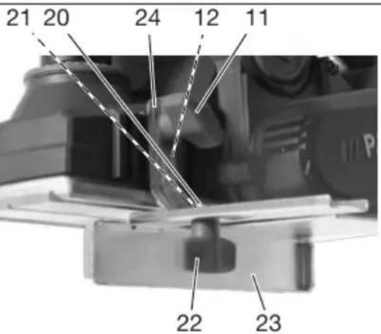
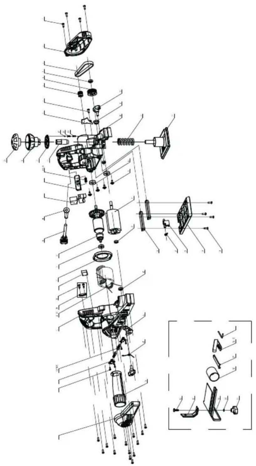
Explosionszeichnung • Exploded view • Vue éclatée • Vista esplosa • Vista explosionada • Explosietekening • Eksploderet tegning • Robbantott ábra • Widok rozłożony • Rozložený pohled • Rozložený pohlád
PEH 30 E5
informativ • informative • informatif • informatief • informativo • informatív • informacyjny • informační • informatívny




- Elektrische schaafmachine
- Introduction
- Proper use
- Scope of delivery/accessories
- Overview
- Fig. A
- Fig. B
- Fig. C
- Description of functions
- Technical data
- ⚠️ CAUTION! Hearing damage! Wear ear protection.
- Safety information
- Meaning of the safety information
- Pictograms and symbols
- Symbols on the device
- General Power Tool Safety Warnings
- WORK AREA SAFETY
- ELECTRICAL SAFETY
- PERSONAL SAFETY
- POWER TOOL USE AND CARE
- SERVICE
- Safety instructions for planers
- Additional safety instructions
- Residual risks
- Preparation
- Control elements
- Removing and fitting the chip ejector
- Notes
- Removing the chip ejector
- Fitting the chip ejector
- Using the parallel guide
- Fitting the parallel guide (Fig. C)
- Adjusting the parallel guide (Fig. C)
- Using a rebate depth stop
- Procedure (Fig. C)
- Connecting dust extraction
- Procedure
- Rotating or replacing the planer blades
- Dismantling the planer blade (fig. A)
- Assembling the planer blade (fig. A)
- Aligning the planer blade (fig. A)
- Operation
- Working instructions
- Information on planing
- - Cutting depth
- Information on chamfering edges
- Information on planing rebates
- Switching on and off
- Switching on
- Switching off
- Transport
- Cleaning, maintenance and storage
- Cleaning
- Cleaning after operation
- Maintenance
- Replacing the drive belt
- Tools required
- Procedure (Fig. B)
- Storage
- Disposal/environmental protection
- Directive 2012/19/EU on waste electrical and electronic equipment:
- Service
- Guarantee
- Terms of Guarantee
- Guarantee Period and Statutory Claims for Defects
- Guarantee Cover
- Processing in Case of Guarantee
- Repair service
- Service Centre
- Importer
- Spare parts and accessories
- Translation of the original EU declaration of conformity
- Sommaire
Brand : PARKSIDE
Model : PEH 30 E5
Category : Electric planer